Another Low Power TV installation

One of the many projects we are currently finishing up. Over-The-Air TV is making a comeback.

A few things about LPTV; These stations usually have an ERP of 15 KW or less, and they are a secondary service, like FM translators, which a full-power TV station can displace.
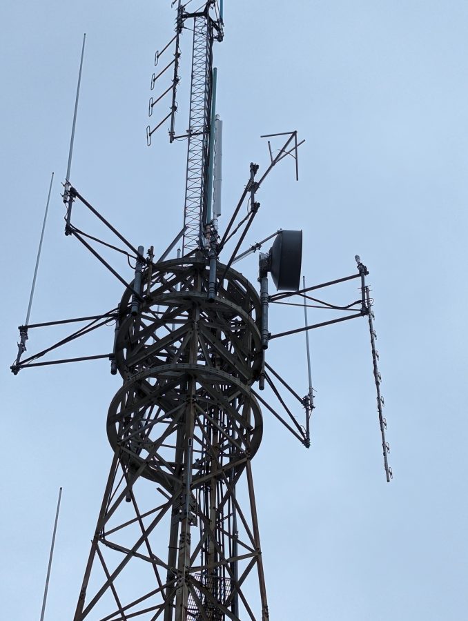
Alive Telecom ATC-BCE48BB-V3-31 UHF slot antenna

This is an ATT microwave site built in 1977 according to county records. This may have been one of those VHF Mobile Telephone sites which existed before cellular telephone systems. ATT owned it until 2022 when it was sold to a private business.

This station is on channel 31 or 575 MHz center frequency. UHF TV stations often use slot antennas, which have gobs of gain. Slot antennas are simple designs that have a broad bandwidth and until recently were mostly horizontally polarized. This particular antenna is elliptically polarized which is becoming more common as TV providers are looking at mobile video applications.
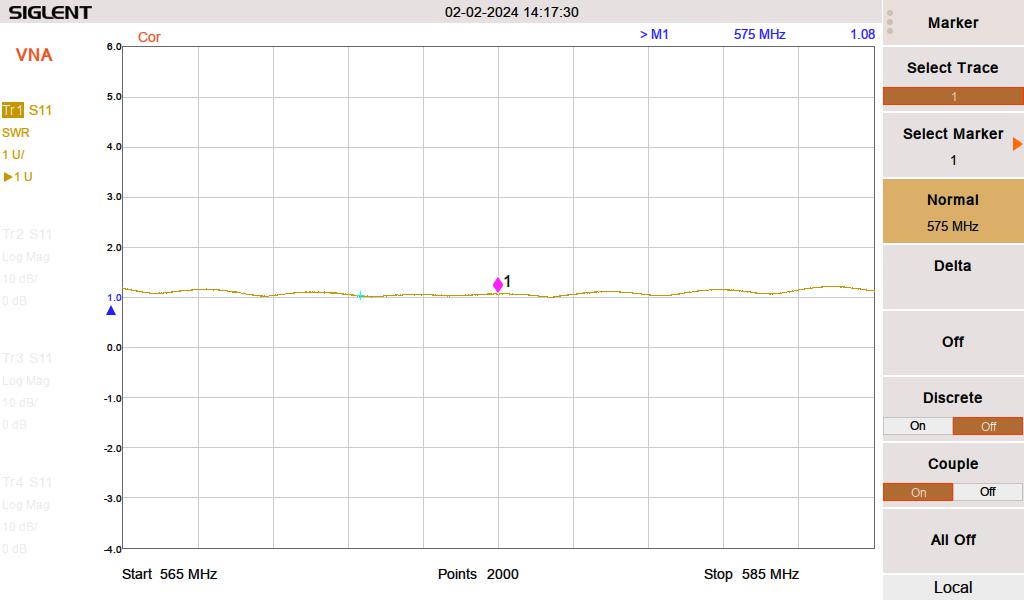
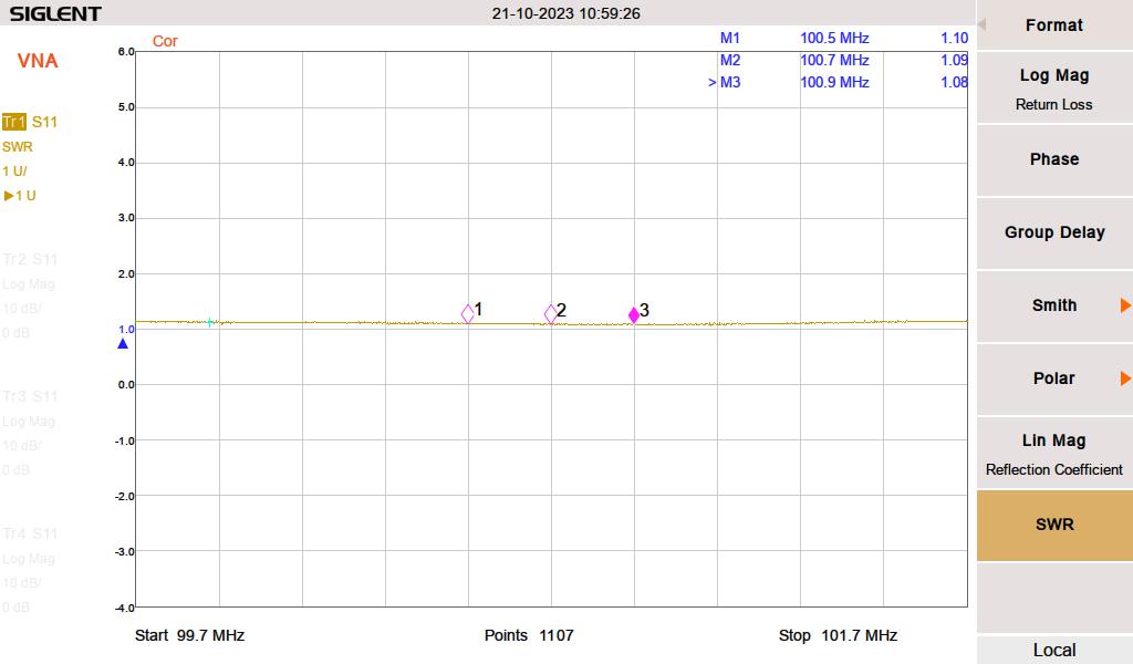
WZPK 20 MHz VSWR sweep
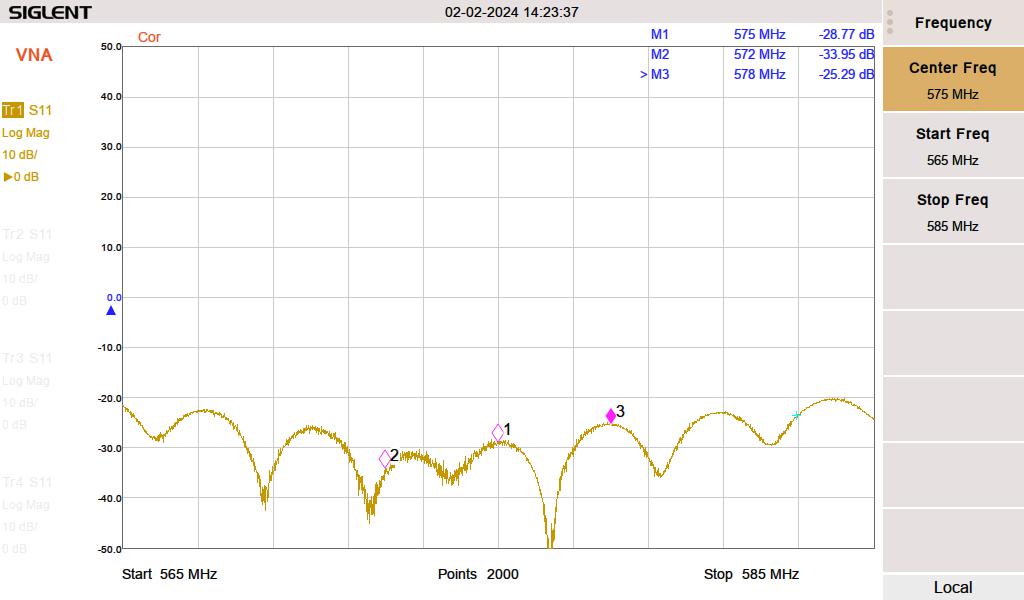
WZPK 20 MHz return loss
Example of UHF slot antenna with Radome cover removed

Slot antennas are the inverse of a dipole antenna. A dipole is two conductive poles approximately 1/2 wavelength surrounded by free space whereas a slot antenna is 1/2 wavelength of free space surrounded by a conductive plane. The width of the slot determines the bandwidth of the antenna. Radiation from a dipole is in the plane of the two poles versus the radiation from a slot that is perpendicular to the slot. At UHF frequencies, many slots are placed on the radiating plane, giving large gain figures.
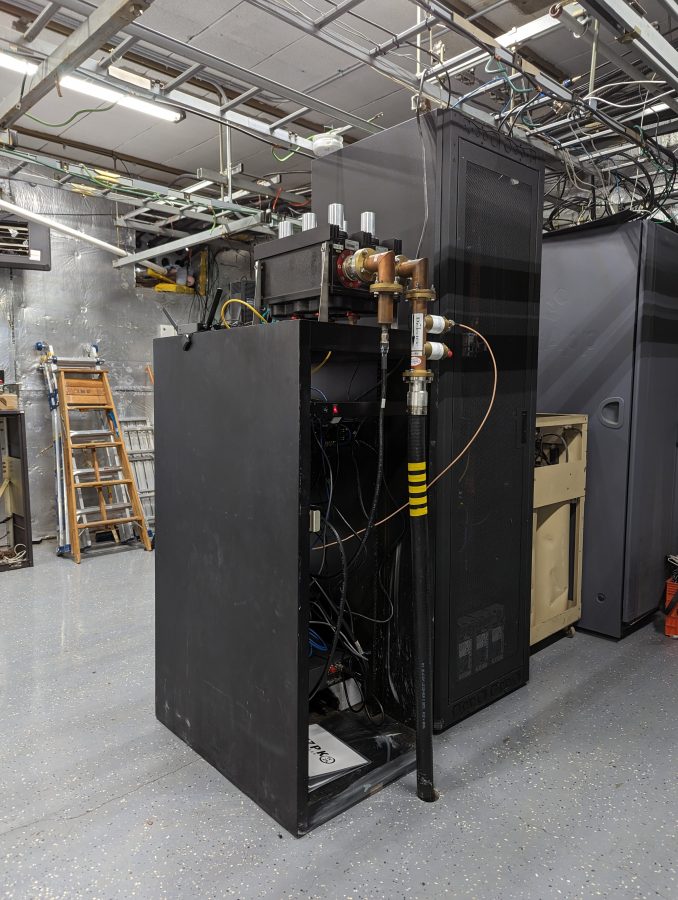
Transmitter rack with 6-pole Comtech mask filter

All TV transmitters require a bandpass or mask filter. This is to keep out-of-band emissions out of the tightly packed TV spectrum.
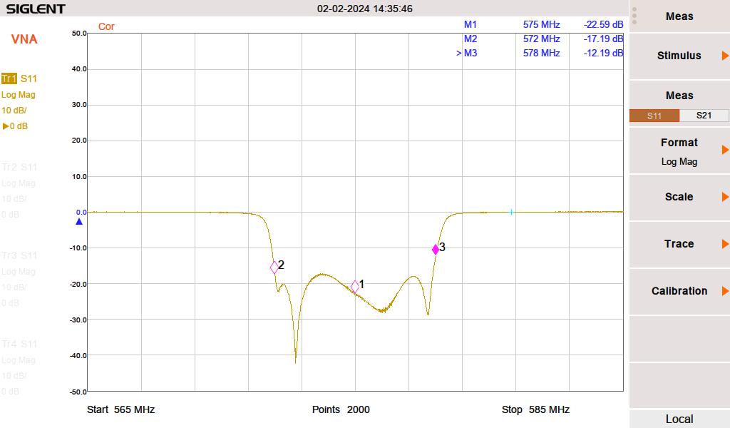
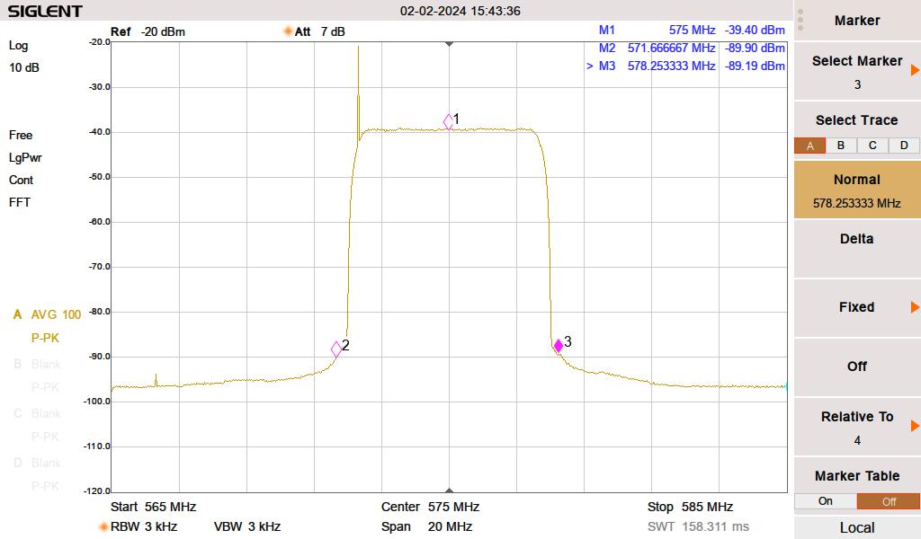
S11 return loss, looking at the antenna through the mask filter
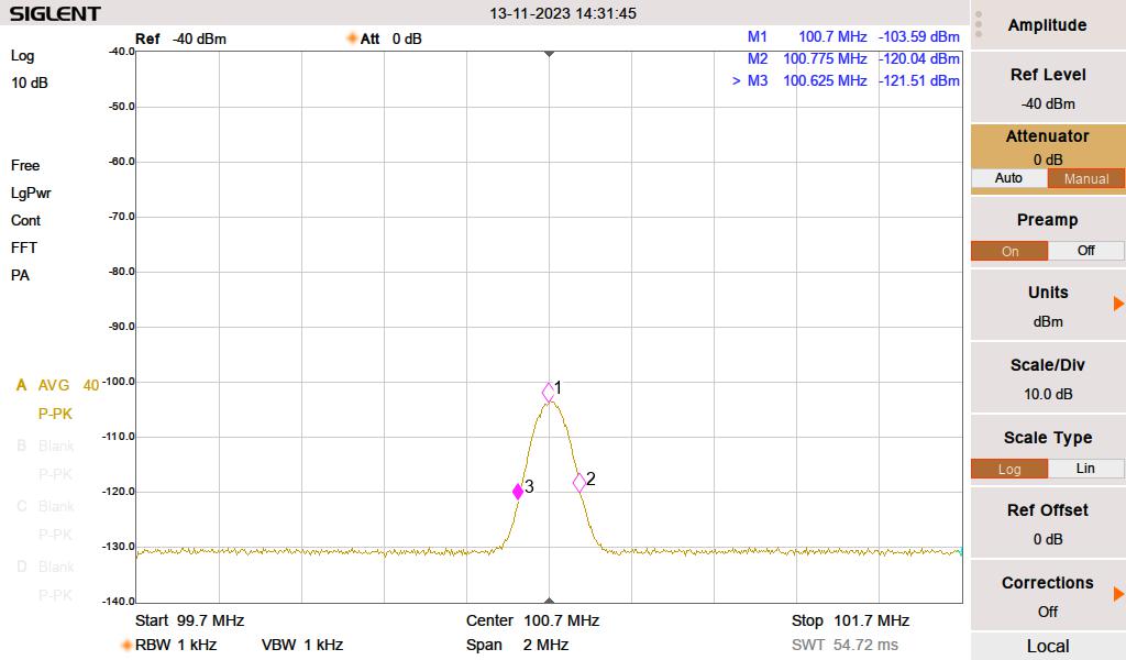
Post-mask filter channel bandwidth

These filters need to attenuate the upper and lower shoulders of the digital carrier by 46dB +/- 3.25 MHz from the center frequency.
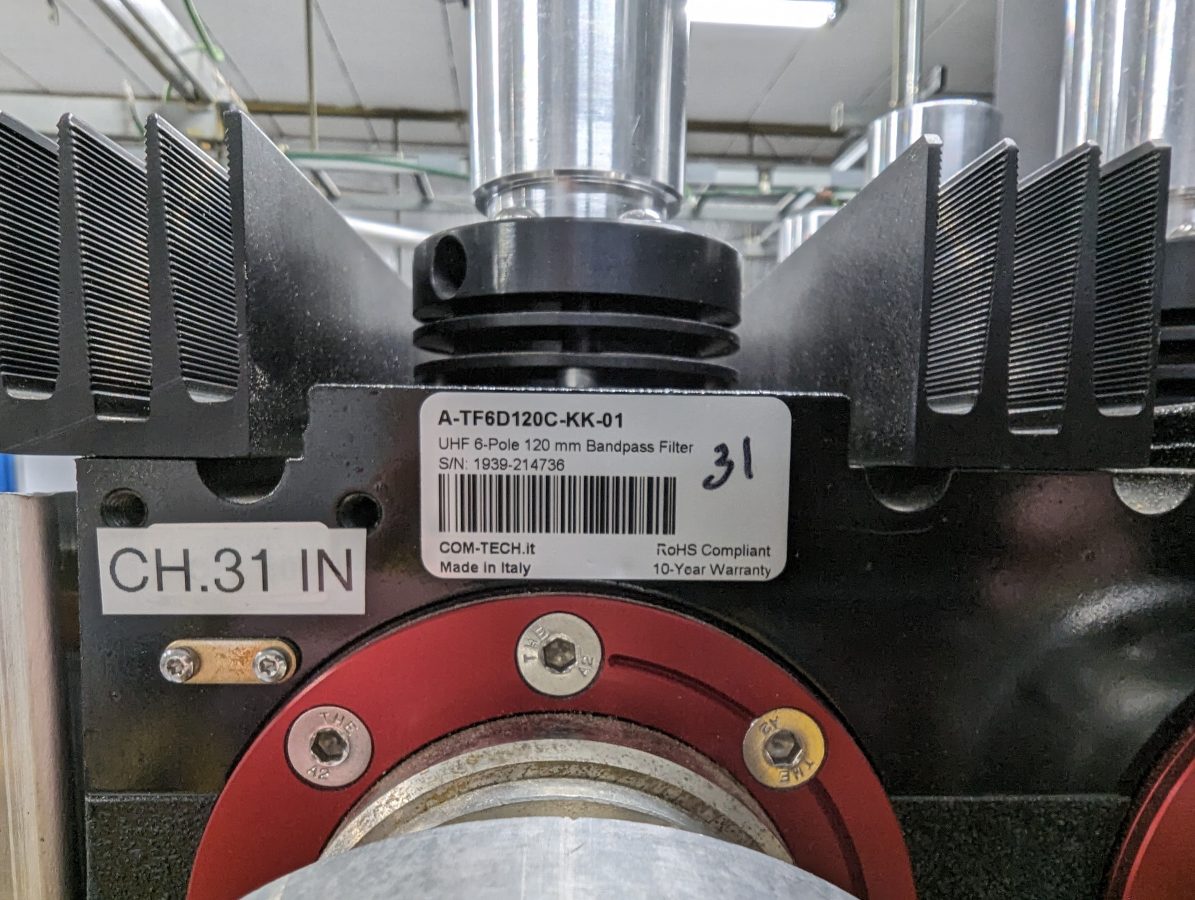
Comtech 6 pole UHF TV mask filter

These are fairly straightforward filters, this one has six cavities with plungers that slide in and out to adjust the tuning. I watched one of these get retuned in the field, it takes quite a bit of time and patience to complete and requires a two-port network analyzer.
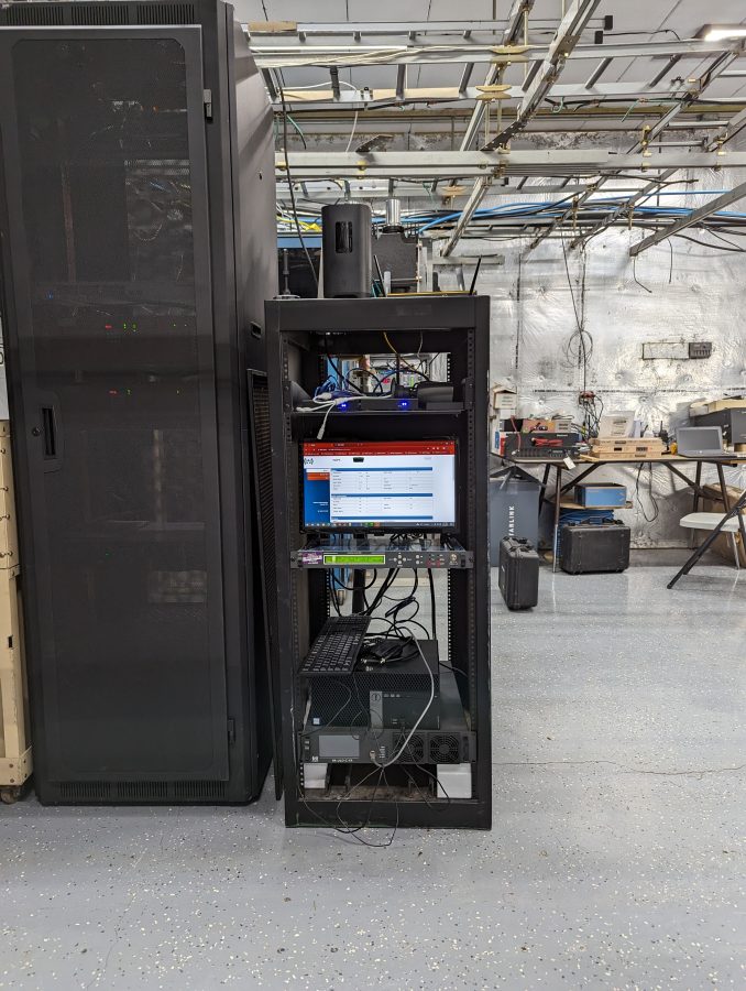
400-watt UHF amplifier, exciter, and IT gear; WZPK-LD

With the TPO of 400 watts, the ERP is 4.7 KW horizontal and 2.35 KW vertical.
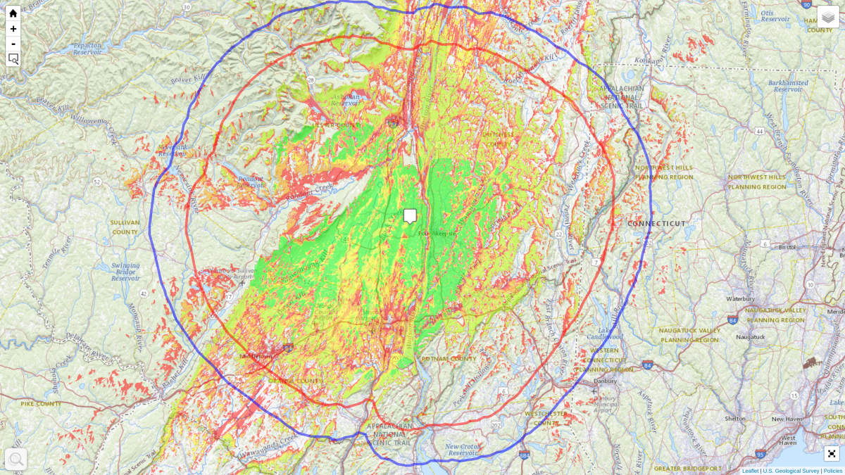
Longley Rice coverage map; green is easy indoor, yellow is outdoor, red is difficult outdoor antenna

So, why bother with all of this? Indeed that is a good question. As cable companies continue to raise their rates (the average cable TV bill is $250 or so) people are looking for alternatives. Cord cutting is a thing and OTA (over-the-air) TV as well as OTT (over-the-top or direct streaming) are popular alternatives.
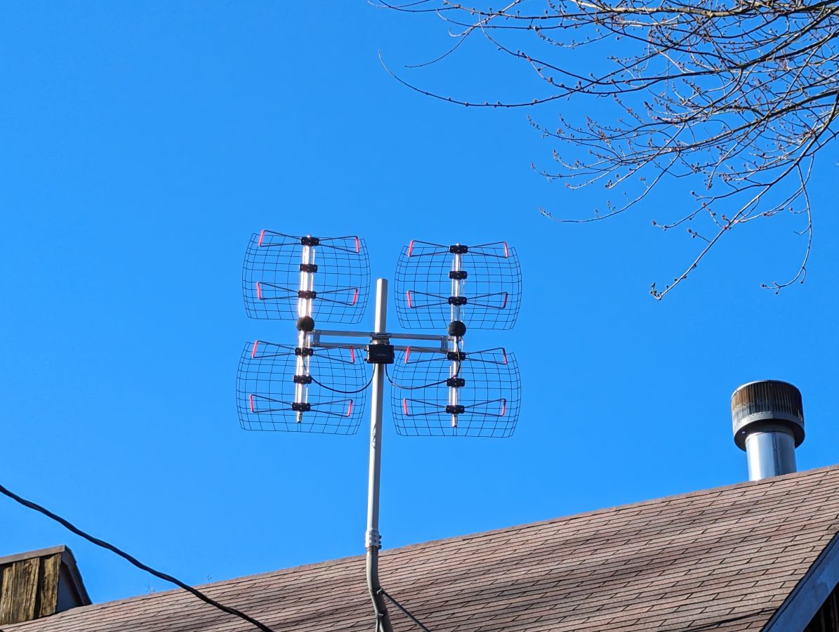
UHF “Bow Tie” consumer TV antenna

This station will run France 24 English service and NASA TV to start. Other things you can find on Low Power TV stations; Heartland (mostly country music with some cooking shows mixed in), Retro (old movies), Rewind TV (Old TV shows), Buzzr (old game shows), Court TV, Weather Nation, News Net, etc. More information on OTA TV networks can be found here: https://en.wikipedia.org/wiki/List_of_United_States_over-the-air_television_networks

Rabbit Ears has a good signal search page if you are interested in OTA TV: https://www.rabbitears.info/searchmap.php

More information on Low Power TV (or Local Power TV) and be found here: https://www.lptvba.org/

For a sometimes interesting discussion on cord cutting in general, try this: https://old.reddit.com/r/cordcutters/

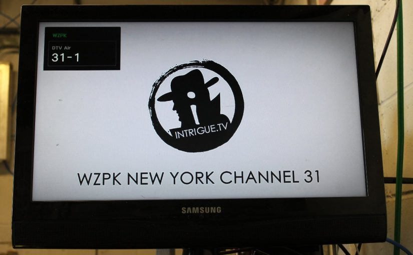
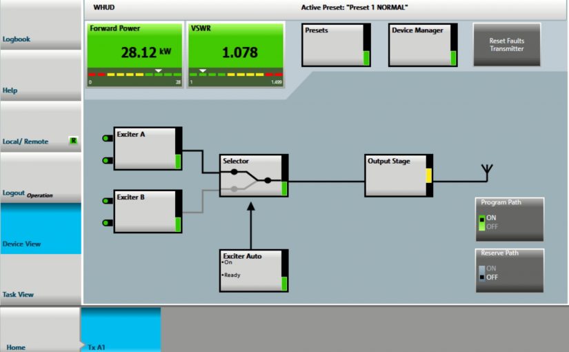
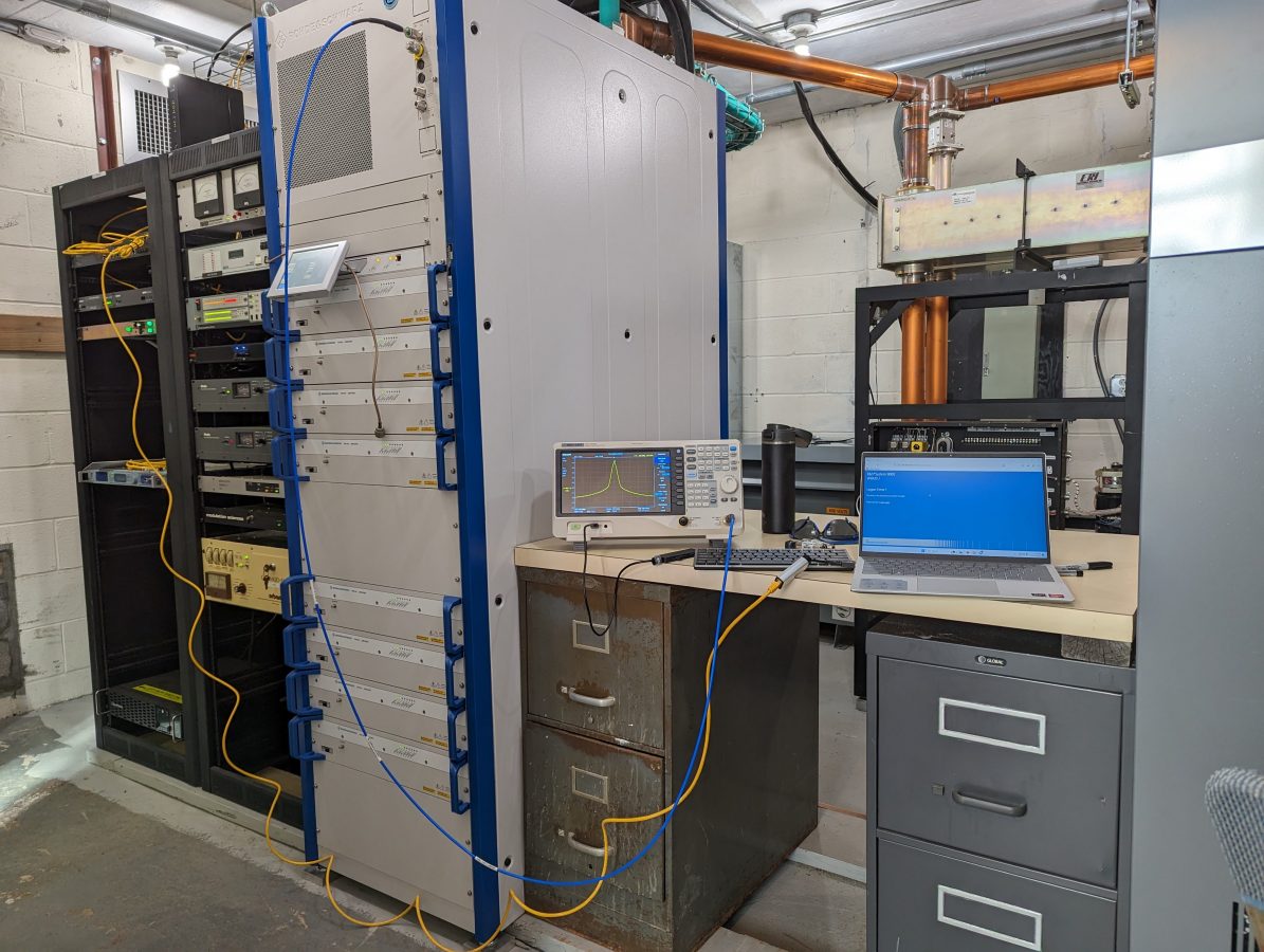
The Rhode and Schwarz THR9 transmitter

Part II of II

This thing is on the air! There are still some tidying-up things to finish, but it is up and running and sounds great! Here are some pictures of various stages of the installation work:

Making harmonic measurements

The filing cabinets hold manuals and spare parts. There is not a lot of room left in this building, so workspace is at a premium. The filing cabinet on the left needs some Windex and elbow grease.

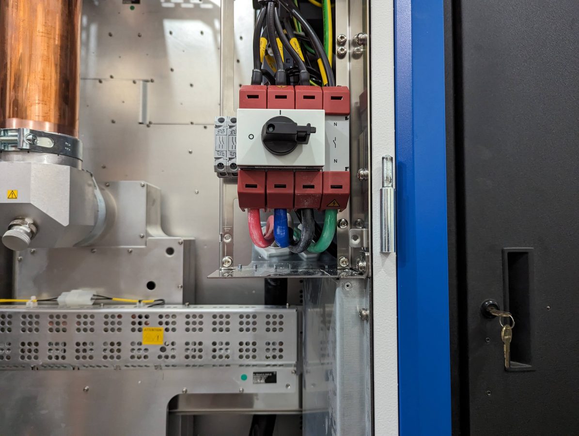
Main disconnect and conduit to 400-volt transformer
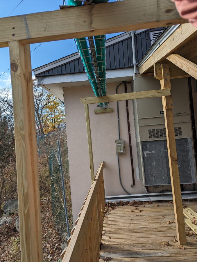
Outdoor coolant run
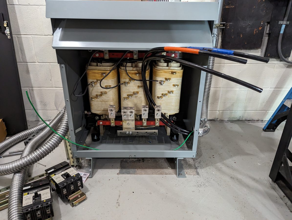
3/0 cables, 240-volt input to Hammond HPS Sentinal K transformer

The transformer does not have a neutral reference to the power company. The neutral for the transmitter is derived from the Y output connection. The transformer is also designed to suppress harmonics from non-linear loads like switching power supplies.

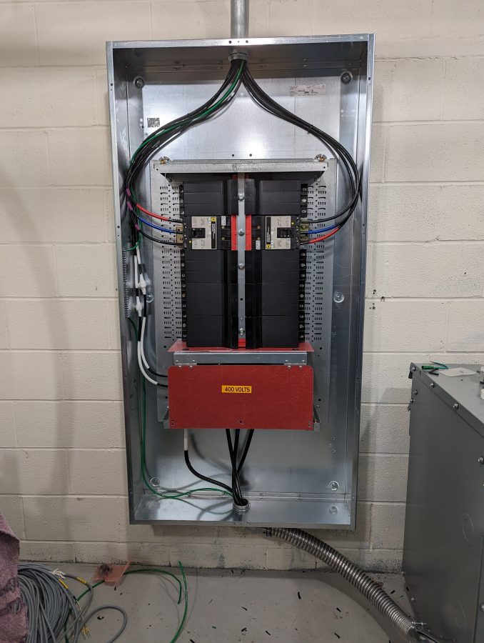
Wiring in Square D I line panel
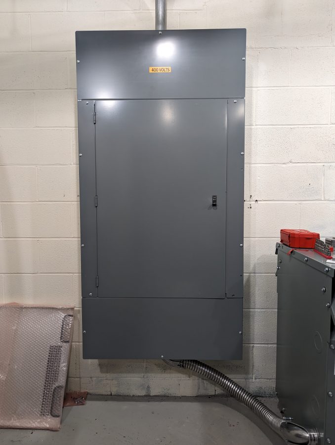
Square D I-line panel rated for 600 volts
#2 SOOW cable feeding upper and lower sections of transmitter
Wiring to disconnect switch on transmitter
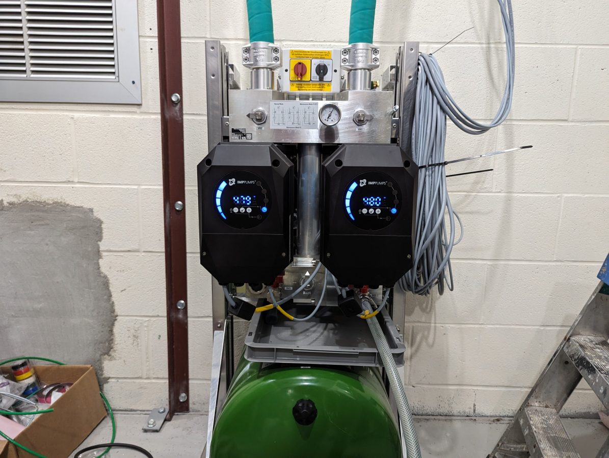
Pump station during system fill
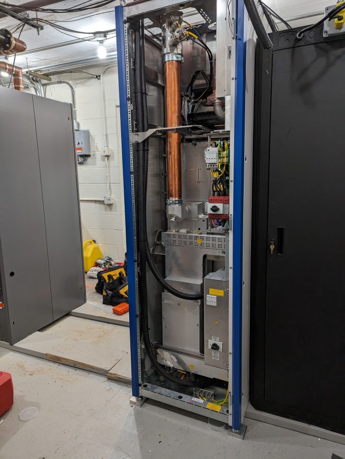
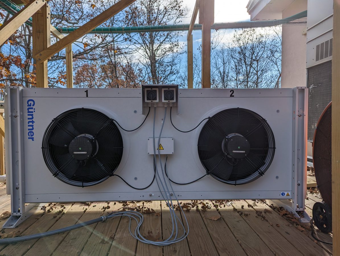
Heat exchanger

The wiring on the pump station and heat exchanger needs a little more work. The client wanted to get this on the air as soon as possible because they are in a book and were running at 50% power. Once things calm down a bit, I will put the backup transmitter on for an afternoon and properly dress the wires.

FM modulation analysis

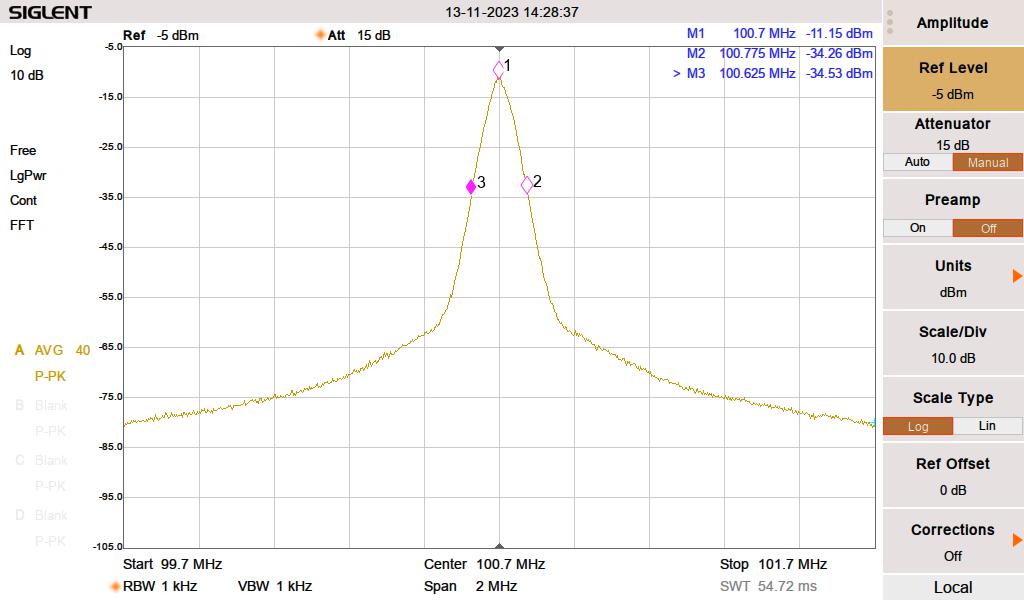
I found this FM modulation analysis function on my spectrum analyzer very useful. The station deviates slightly more than the allocated 75 KHz because of a subcarrier. Overall, it looks good. I measured the harmonics out to the 10th harmonic, most of them were in the noise floor. A few made a slight appearance, but well within FCC tolerances. It is important to document this, as this site has colocated cellular carriers and several E911 services.

FCC part 73.317 states:

(d) Any emission appearing on a frequency removed from the carrier by more than 600 kHz must be attenuated at least 43 + 10 Log10 (Power, in watts) dB below the level of the unmodulated carrier, or 80 dB, whichever is the lesser attenuation.

47CFR 73.317
WHUD fundamental
WHUD fundamental with two Mini-Circuits NHP-200 high pass filters installed

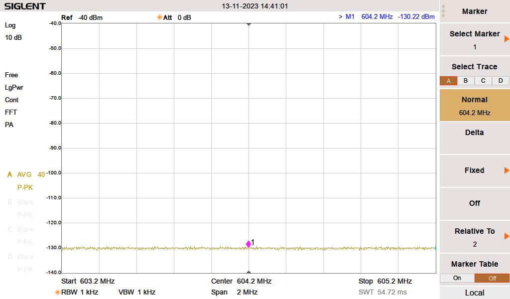
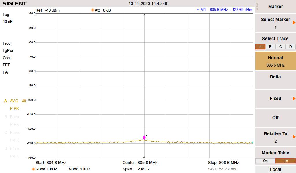
The rest of the harmonics were measured down to -130 dB with the two NHP-200 high-pass filters in the circuit. The 3rd, 4th, 5th, 6th, and 8th harmonics were unmeasurable. The 8th, 9th, and 10th made slight appearances.

WHUD 6th Harmonic, noise floor
WHUD 8th harmonic makes a little appearance
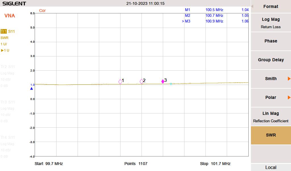
Main antenna VSWR
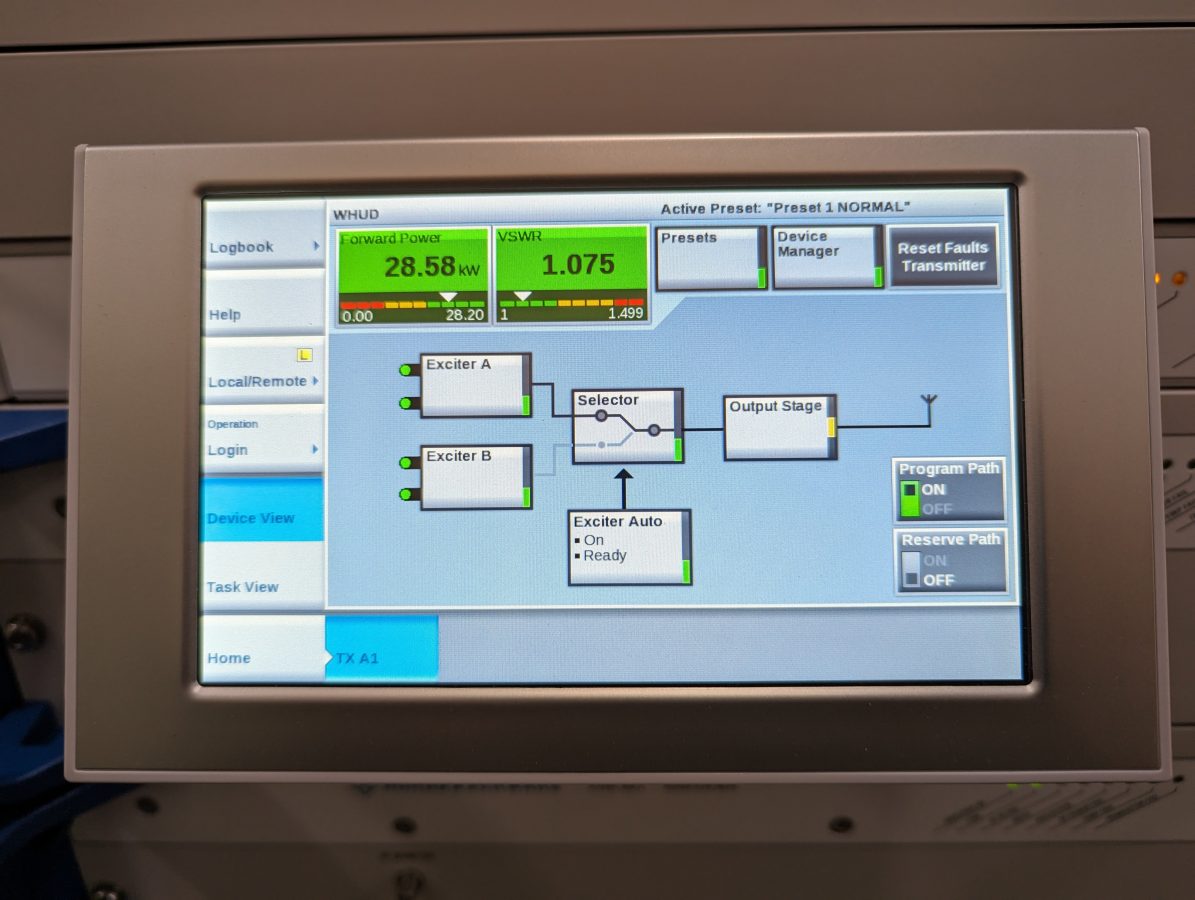
Antenna VSWR according to the transmitter directional coupler

Pretty close, the VNA was inserted at a patch panel, which is the last thing before the transmission line leaves the building. The transmitter goes through an ERI switchless combiner, which probably gives it a slightly better load.

Backup antenna SWR

Aside from the finishing details, I need to keep an eye on this for a week or so and top off the Heat Transfer Fluid as needed. It takes a bit of time to get all of the air out of the coolant loop. Another thing; the operating pressure on this is 4 Bar, which is almost 60 PSI. That is higher than other liquid-cooled transmitter systems I have installed before.

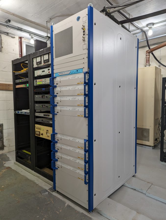
The Rhode Schwarz THR9 transmitter

This is part I of II.

We are in the process of installing an R&S 40 KW liquid-cooled FM transmitter. My first comment; these are well-built units. A quick look at the machining of the parts indicates attention to detail is a key design feature.

As the price of electricity continues to rise, liquid-cooled transmitters for this power level make a lot of sense.

Rhode Schwarz THR9 VHF transmitter

This installation is for Pamal Broadcasting’s WHUD, Peekskill, New York. The site has undergone major upgrades in the last few years. The original 1958 World Tower Utility 80 was replaced a year ago with this Valmont 60X394. Two cell carriers, two translators, and several E911 services are now colocated on the tower.

Valmont 60X394 tower, WHUD Peekskill, NY

The transmitter building is also the original cinder block structure from 1958. When it signed on, the station had a Gates FM5B 5 KW transmitter, an RCA BFA-7, 7-bay horizontally polarized antenna with an ERP of 20 KW. In 1970, that antenna was changed out to a 6-bay circularly polarized ERI with a Harris FM20H transmitter, increasing the ERP to 50 KW. As of now, the station has a 4-bay ERI SHP-4-A-C main antenna and the TPO is 28 KW for the same 50 KW ERP. As the station’s power increased, the building became a little bit smaller than optimal. We needed to rearrange some equipment to gain space for the pump station and step-up transformer.

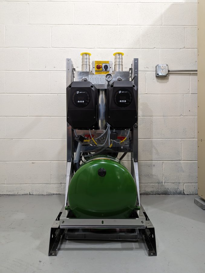
Pump Station
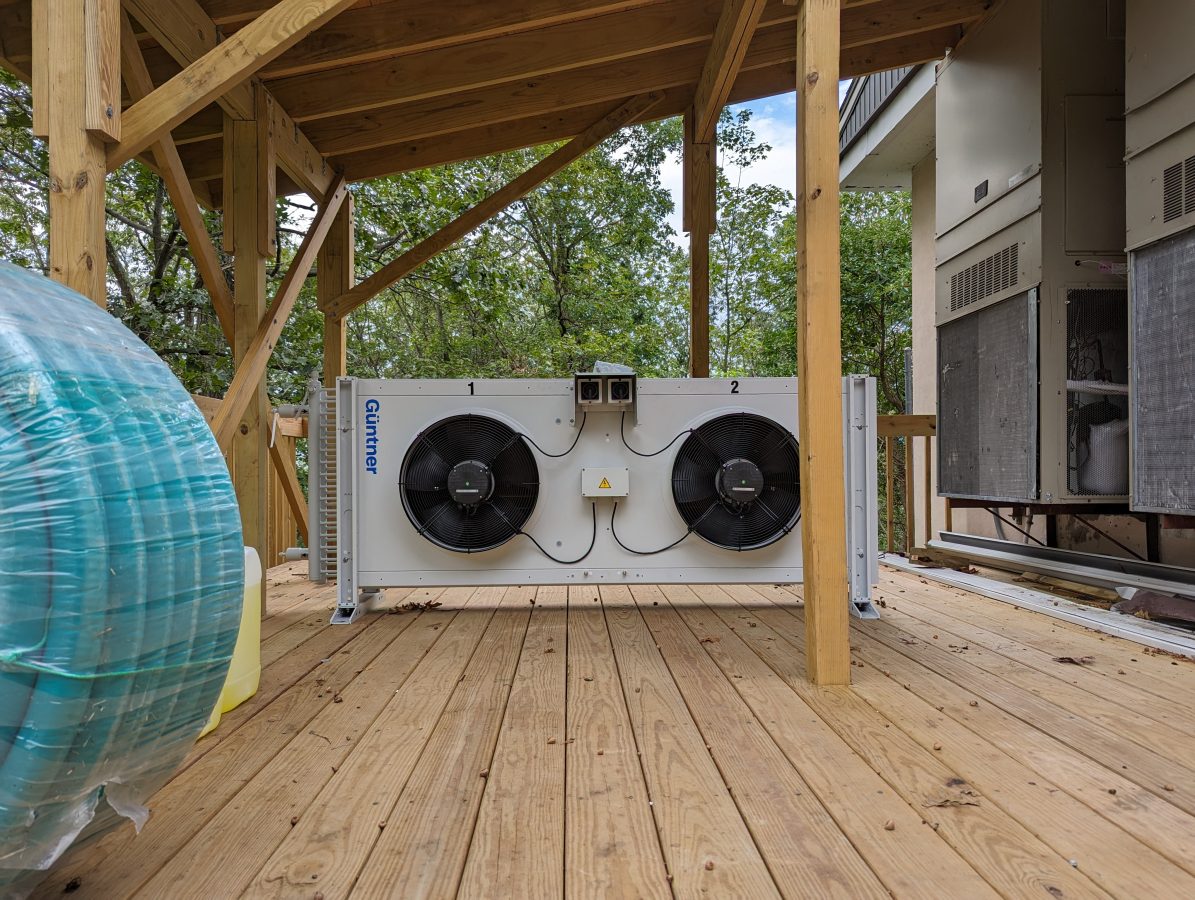
Heat Exchanger

Rhode Schwarz recommended installing a step-up transformer for the incoming AC mains. The power supplies run most efficiently with 400 volts AC.

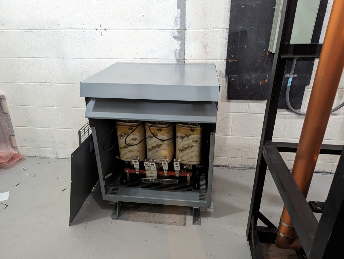
Hammond HPS Sentinel K dry core transformer
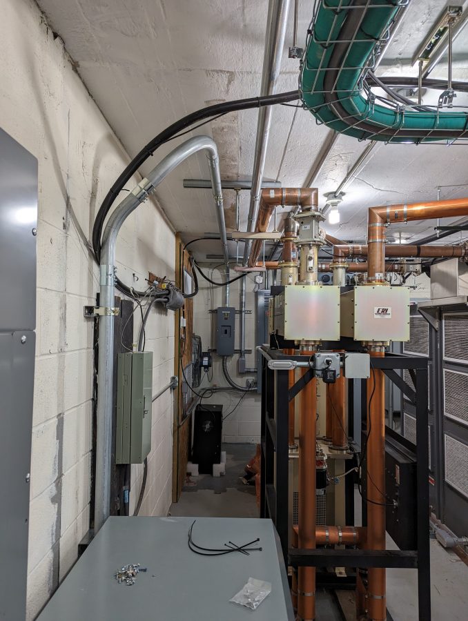
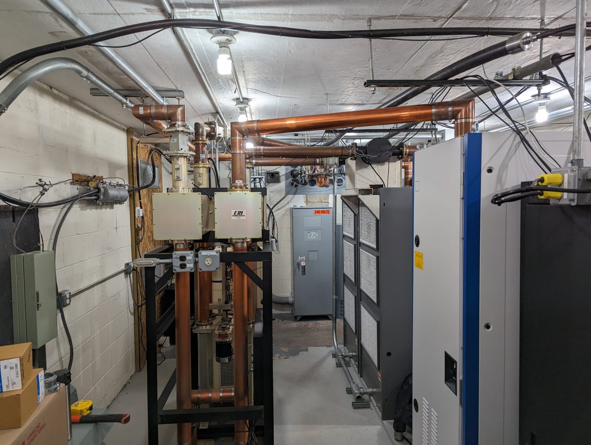
The Rhode Schwarz RF connection to an ERI switchless combiner

We decided to reuse the ERI switchless combiner left over from the Nautel V-40 installation. There are two Nautel V-10 transmitters with a hybrid combiner that are to be used as a backup. We won’t be running this as a combined transmitter operation, it is a way to save money rather than install a separate 3-inch coax switch. I will build a simple control panel to move the combiner position either all the way up (THR9) or all the way down (V-10s).

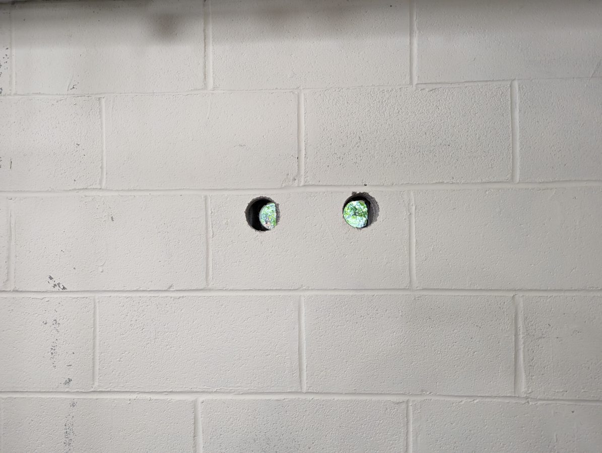
2.5 inch core drilled holes for coolant supply and return

Working on the liquid cooling system. I used a core drill to make the supply and return lines to the outdoor heat exchanger. I made sure that I had the shop vac (with a HEPA filter) running while drilling so that all of the concrete dust was captured. That stuff can get everywhere and has a bad tendency to destroy motor bearings. Whatever plant made these blocks in 1958, they used some hard material. It took a while for my masonry drill to get through them.

Working with rigid transmission line

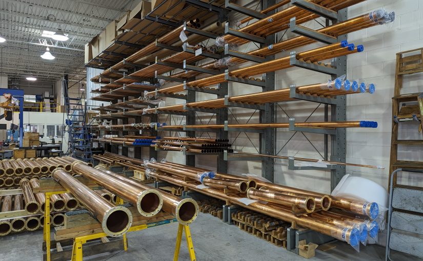
Update: This post is from several years ago (January 31, 2018), however, I did a fairly major revision and added a lot of information, so I am bumping it to the top of the pile. The header picture is from the Myat facility in Mahwah, New Jersey.

Installing transmitters requires a multitude of skills; understanding the electrical code, basic wiring, RF theory, and even aesthetics play some part in a good installation.  Working with rigid transmission line is a bit like working with plumbing (and is often called that). Rigid transmission line is often used within the transmitter plant to connect to a four-port coax switch, test load, backup transmitter, and so on.  Sometimes it is used outside to go up the tower to the antenna, however, such use has been mostly supplanted by Heliax-type flexible coax.

We completed a moderate upgrade to a station in Albany; installing a coax switch, test load, and backup transmitter.  I thought it would be interesting to document the rigid line work required to complete this installation.  The TPO at this installation is about 5.5 KW including the HD carriers.  The backup transmitter is a Nautel VS-1, analog only.

This site uses a 1 5/8-inch transmission line.  That line is good for most FM installations up to about 10-15 Kilowatts TPO.  Beyond that, 3-inch line should be used for TPOs up to about 30 Kilowatts. Above 30 KW TPO, 4 inch or greater line is required. There are a few combined FM stations that are pumping 80 or 90 KW up to the antenna. Those require 6 inch or greater line.  Even though the transmission lines themselves are rated to handle much more power, reflected power often creates nodes along the line where the forward power and reflected power are in phase.  This can create hot spots and if the reflected power gets high enough, flashovers.

This brings up another point; most rigid line comes in 20-foot sections. There are certain FM frequencies that require different lengths due to the aforementioned nodes that fall along the 1 wavelength intervals. If one of those nodes happens on a flange, that could create problems.

  • Frequencies between 88.1 and 95.9 MHz, use 20-foot line sections
  • Frequencies between 96.1 and 98.3 MHz, use 19.5-foot line sections
  • Frequencies between 98.5 and 100.1 MHz, use 19-foot line sections
  • Frequencies between 100.3 and 107.9 MHz, use 20-foot line sections

TV frequencies are much more complicated. The large channel width and much larger spectrum use means that close attention needs to be paid to line section length. Since low-power TV and translators may need to change frequency, those stations often use Heliax instead of rigid line.

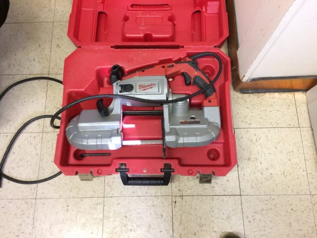
Milwaukee portable band saw

Working with rigid line requires a little bit of patience, careful measurements, and some special tools.  Since the line itself is expensive and the transmission line lengthener has yet to be invented, I tend to use the “measure twice and cut once” methodology.  

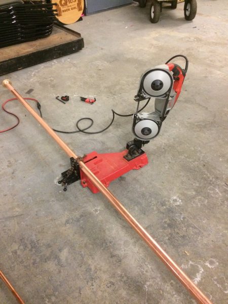
For cutting, I have this nice portable band saw and table.  I bought this particular tool several years ago and it has saved me hours if not days of work at various sites.  I have used it to cut not just coaxial line and cables, but uni strut, threaded rod, copper pipe, coolant line, conduit, wire trays, etc.  If you are doing any type of metalwork that involves cutting, this tool is highly recommended.

Milwaukee 6230N Band Saw with cutting table

There are now Lion battery types of bandsaws which are certainly more portable than this. Still, the table with the chain clamp makes work much easier and the cuts are straight (perpendicular), which in turn makes the entire installation easier.

The next point is how long to cut the line pieces and still accommodate field flanges and inter-bay line anchors (AKA bullets). 

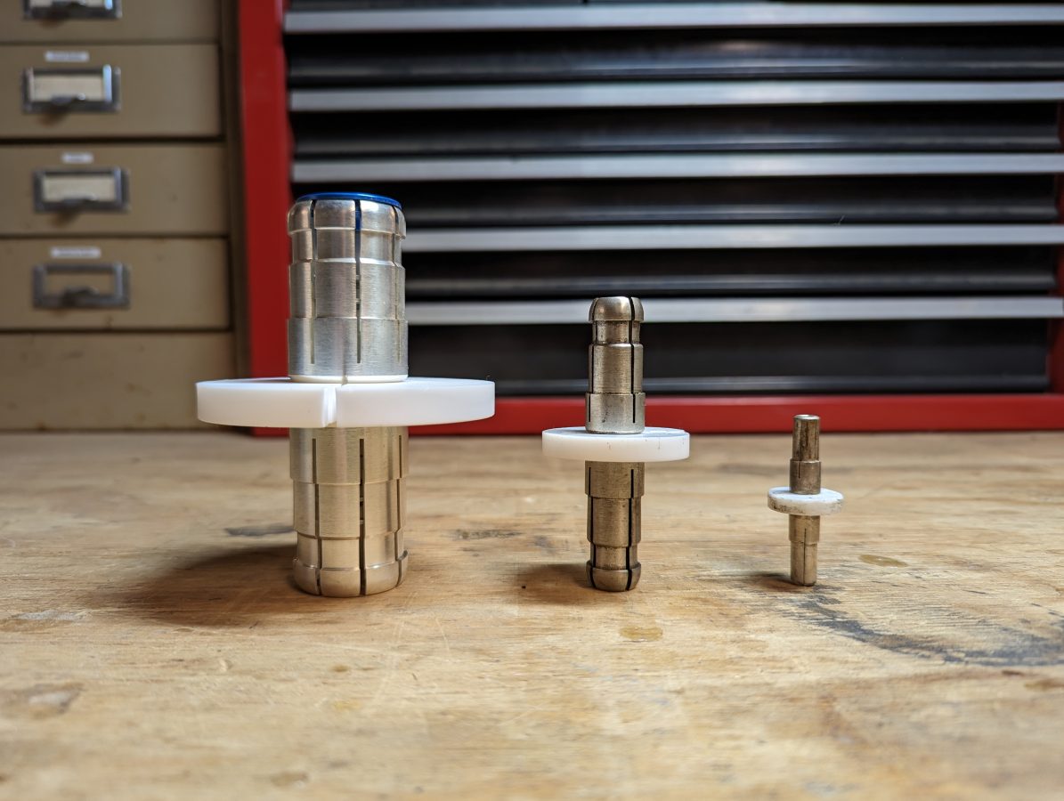
Inner bay line anchor, aka “bullet” 3 1/8 inch, 1 5/8 inch, and 7/8 inch respectively

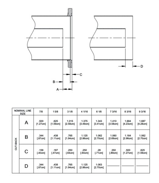
The inner conductor is always going to be shorter than the outer conductor by some amount.   Below is a chart with the dimensions of various types of rigid coaxial cables.

Length cut chart for various sizes of rigid coaxial cables

When working with 1 5/8 inch rigid coax, for example, the outer conductor is cut 0.187 inches (0.47 cm) shorter than the measured distance to accommodate the field flange. The inner conductor is cut 0.438 inches (1.11 cm) shorter (dimension “D” in the above diagram) than the outer conductor to accommodate the inter-bay anchors. These are per side, so the inner conductor will actually be 0.876 inches (2.22 cm) shorter than the outer conductor.  Incidentally, I find it is easier to work in metric as it is much easier to measure out 2.22 CM than to try and convert 0.876 inches to some fraction commonly found on a tape measure.  For this reason, I always have a metric ruler in my tool kit.

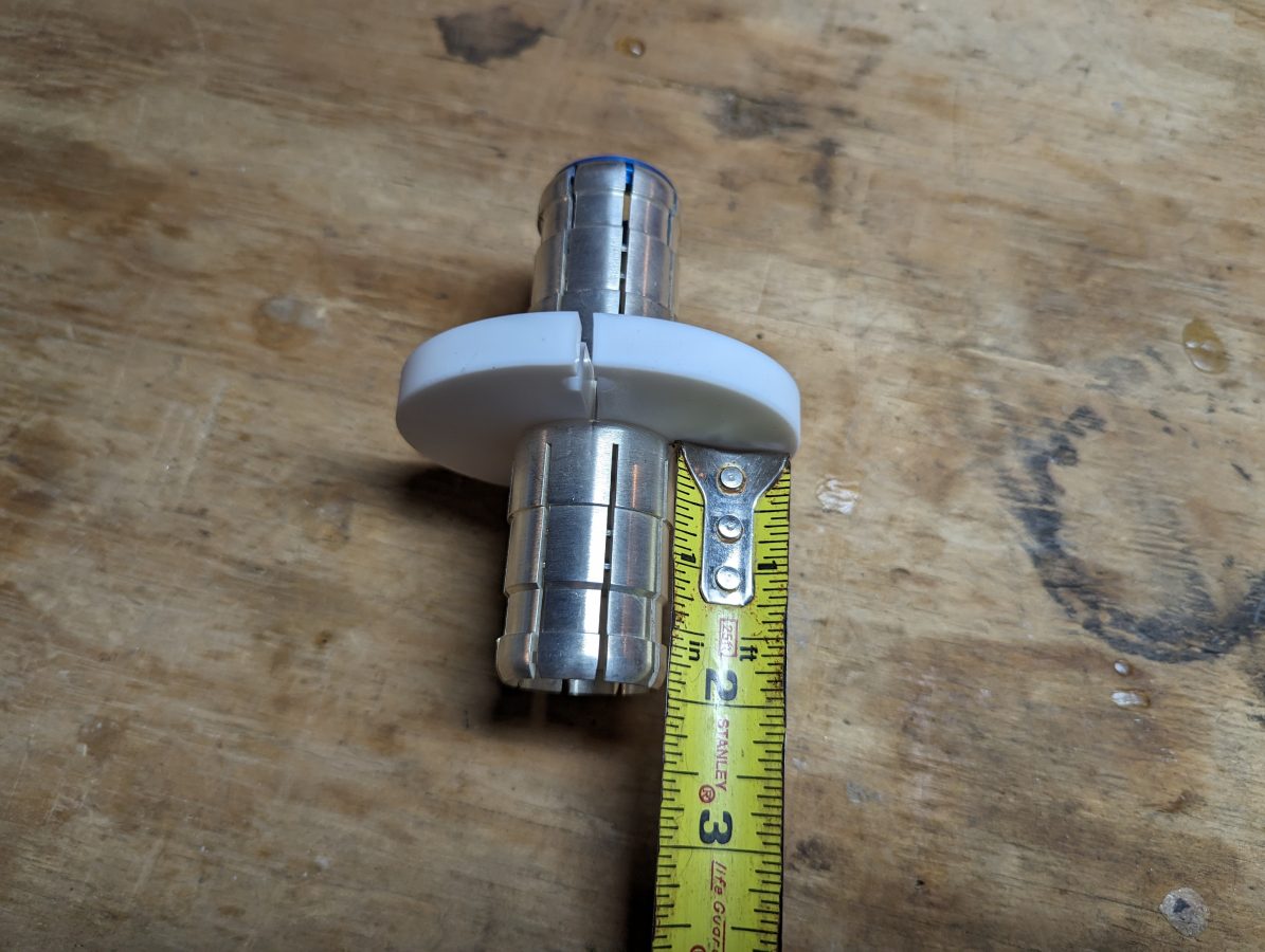
If you do not have a handy chart, you can estimate the inner conductor length by measuring the inner bay anchor from the insulator to the first shoulder. Then multiply by two.

Measuring inner bay line anchor

In this case, the measurement from insulator to shoulder is 11/16th of an inch (17.5 mm). If Clamp On Flange adaptors (AKA field flanges) are being used, don’t forget to account for the small lip (usually less than 1/16th of an inch) around the inside of the flange where the outer conductor is seated. If you are using unflanged couplings instead of field flanges, then you can disregard this.

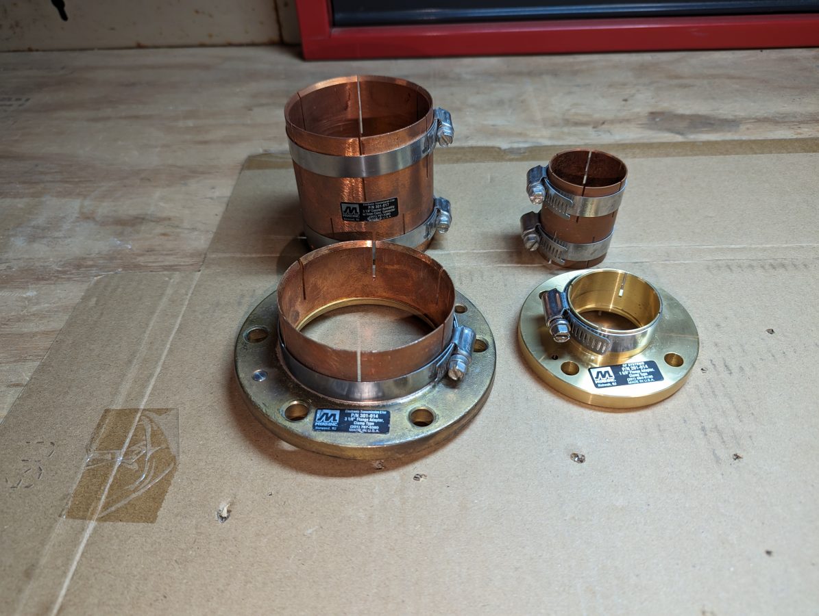
Clamp on Flange adaptors in the front, flangeless couplers in the back
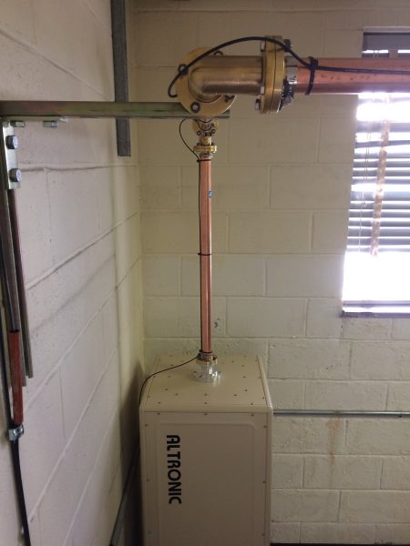
Altronic air cooled 20 KW test load
1 5/8 inch rigid coax run to Altronic air-cooled 20 KW test load
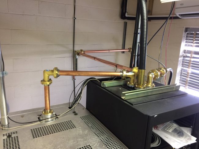
1 5/8 inch rigid coax and 4 port coax switch mounted in top of Middle Atlantic Rack
1 5/8 inch rigid coax and 4 port coax switch mounted on top of Middle Atlantic Rack

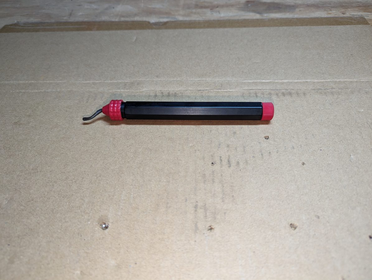
The next step is de-burring.  This is really critical at high power levels.  I use a copper de-burring tool commonly used by plumbers and electricians.

De-burring tool, can be found in the plumbing isle of most big box hardware stors

One could also use a round or rat tail file to de-bur.  The grace of clamp-on field flanges is they have some small amount of play in how far onto the rigid line they are clamped.  This can be used to offset any small measurement errors and make the installation look good.