Part II of II
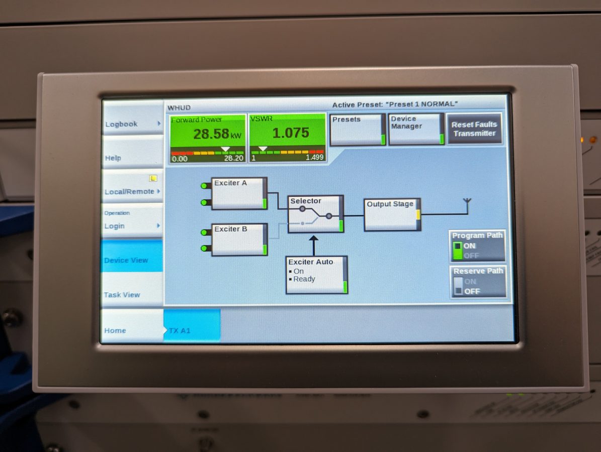
This thing is on the air! There are still some tidying-up things to finish, but it is up and running and sounds great! Here are some pictures of various stages of the installation work:
The filing cabinets hold manuals and spare parts. There is not a lot of room left in this building, so workspace is at a premium. The filing cabinet on the left needs some Windex and elbow grease.
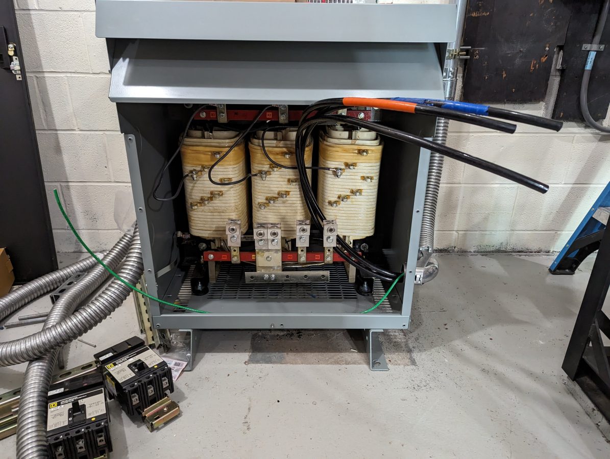
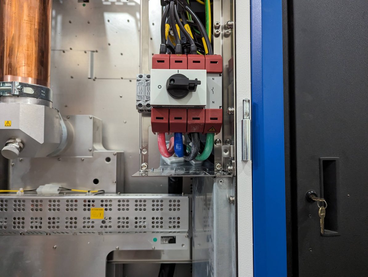
The transformer does not have a neutral reference to the power company. The neutral for the transmitter is derived from the Y output connection. The transformer is also designed to suppress harmonics from non-linear loads like switching power supplies.
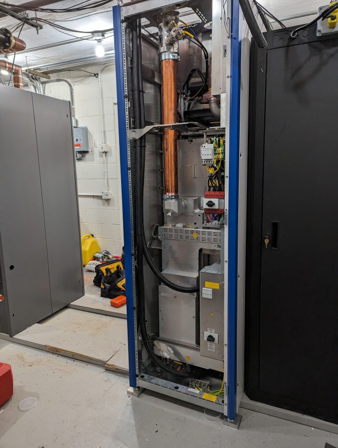
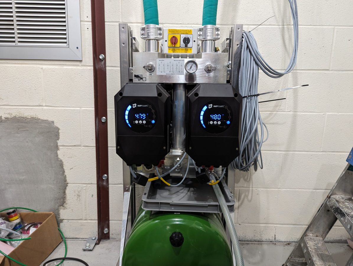
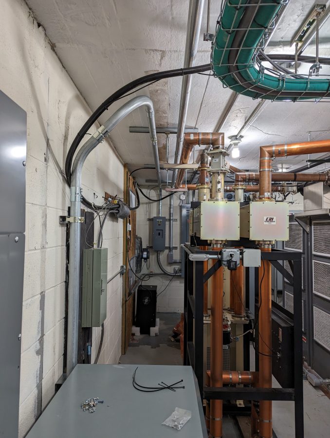
The wiring on the pump station and heat exchanger needs a little more work. The client wanted to get this on the air as soon as possible because they are in a book and were running at 50% power. Once things calm down a bit, I will put the backup transmitter on for an afternoon and properly dress the wires.

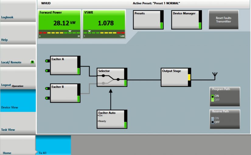
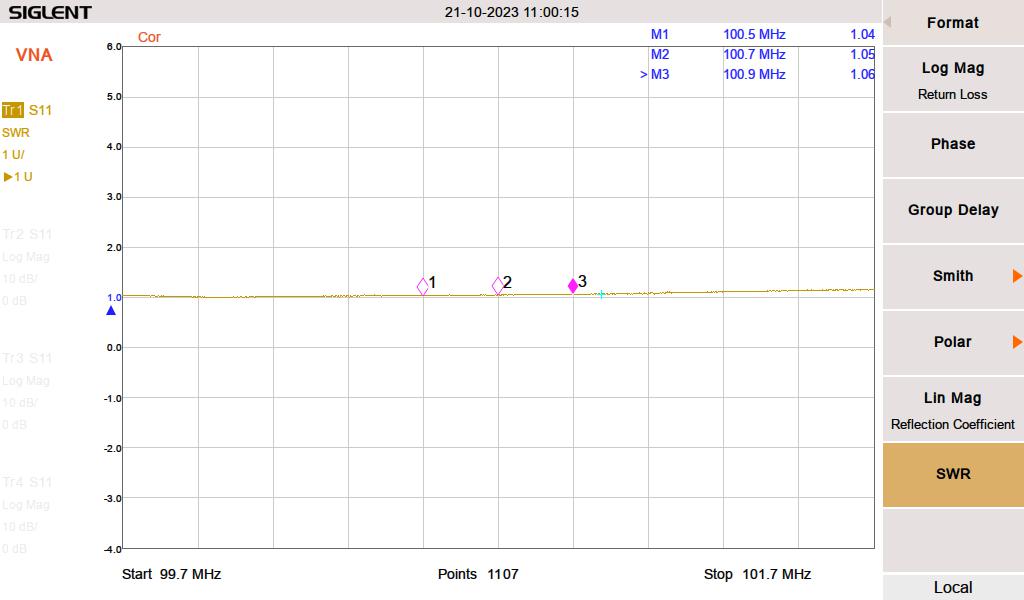
I found this FM modulation analysis function on my spectrum analyzer very useful. The station deviates slightly more than the allocated 75 KHz because of a subcarrier. Overall, it looks good. I measured the harmonics out to the 10th harmonic, most of them were in the noise floor. A few made a slight appearance, but well within FCC tolerances. It is important to document this, as this site has colocated cellular carriers and several E911 services.
FCC part 73.317 states:
(d) Any emission appearing on a frequency removed from the carrier by more than 600 kHz must be attenuated at least 43 + 10 Log10 (Power, in watts) dB below the level of the unmodulated carrier, or 80 dB, whichever is the lesser attenuation.
47CFR 73.317
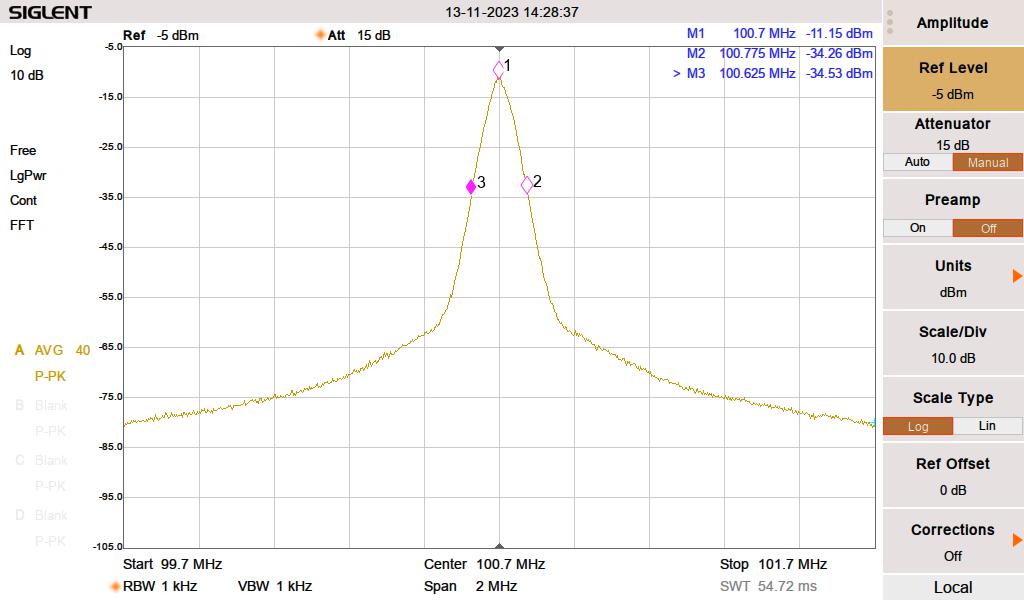
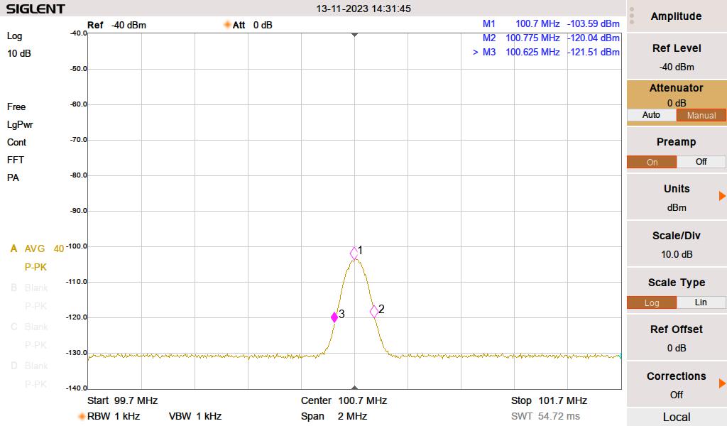
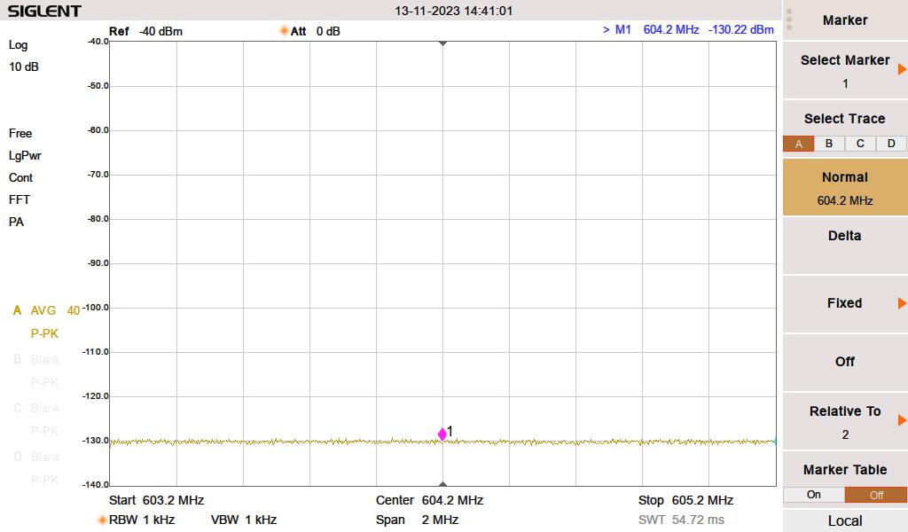
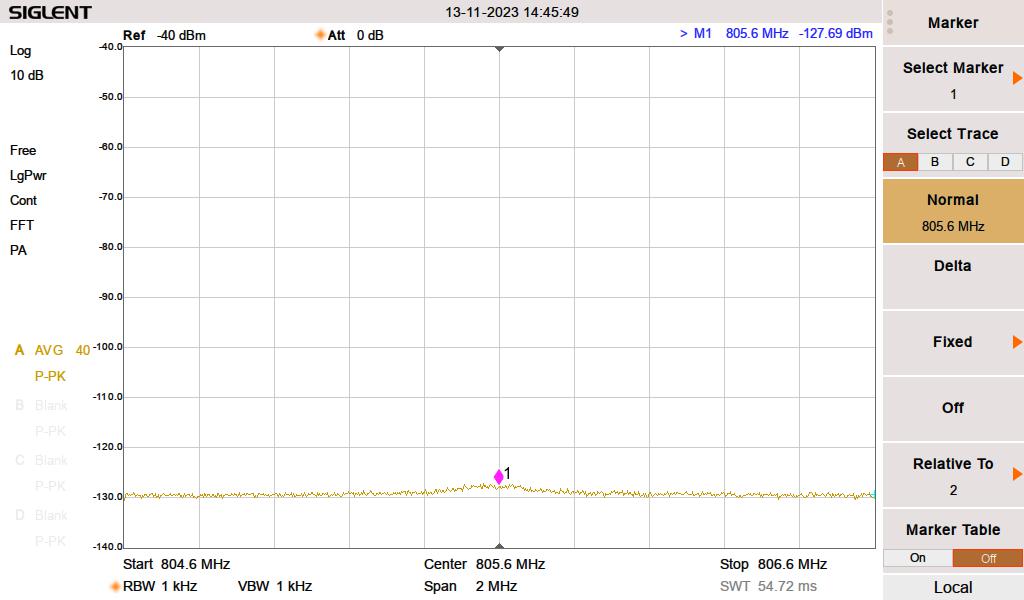
The rest of the harmonics were measured down to -130 dB with the two NHP-200 high-pass filters in the circuit. The 3rd, 4th, 5th, 6th, and 8th harmonics were unmeasurable. The 8th, 9th, and 10th made slight appearances.
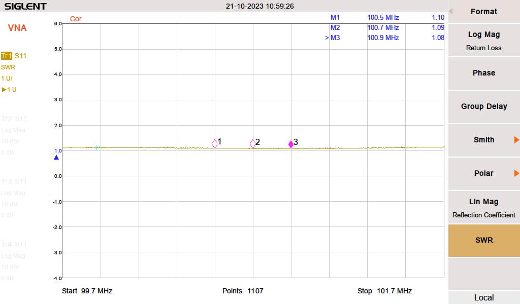
Pretty close, the VNA was inserted at a patch panel, which is the last thing before the transmission line leaves the building. The transmitter goes through an ERI switchless combiner, which probably gives it a slightly better load.
Aside from the finishing details, I need to keep an eye on this for a week or so and top off the Heat Transfer Fluid as needed. It takes a bit of time to get all of the air out of the coolant loop. Another thing; the operating pressure on this is 4 Bar, which is almost 60 PSI. That is higher than other liquid-cooled transmitter systems I have installed before.

Paul,
Do you support any other sites with these transmitters? Just curious to see how R&S is on the ongoing support/service parts availability long term.
I’ve found that this is the second most important factor when selecting capital equipment.
The Nautel rigs don’t appear very old. Why the relegation to standby status? Problems?
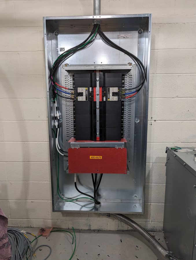
Did the electrician try to correct you “You meant 480 volts not 400, right?”
We have a 480 to 208 3-phase transformer on a Gates-5 that’s wired the same configuration. Also has a grounded shield between windings.
Very nice install Paul! I’m curious as to what model of analyzer you are using and I’m guessing it also has VNA features as well. I would like to get a good VNA, the nano can only do so much…
Thanks!
Mark
Dave, I don’t want to speak too much for Paul, but as the owner of a V7.5 myself, the V series is pretty “elderly” in Nautel-land. I think the last ones were sold over 10 years ago, or thereabouts? It’s technically now three generations out of date (having been followed by the NV, the GV and to some extent the VX series) and the power supplies in them are total unobtainium. Paul was (still is?) doing the lord’s work trying to rebuild these things but the sense I’ve gotten is that it’s getting very difficult to get the parts anywhere. Nautel sells an upgrade kit to use more modern power supplies but you don’t need to replace very many of them before simply buying a new TX becomes more cost-effective. Especially when one considers the lack of the AUI in the V series, and several iffy design decisions made in the V (esp in regards to HD Radio) that were abandoned/re-done in the NV and GV series.
Still, if you have a V series and keep it in a clean, air-conditioned environment with proper grounding/lightning protection? It’ll run fine and sound good on the air. Until it doesn’t, at which point you’re kinda hosed. That’s a decent bargain for a backup transmitter, but definitely less palatable for a main.
Dan: I agree with you about parts availability, this is one of the problems with the Nautel V series units. Before we recommended this to the client, I spoke with several different TV engineers and they all said basically the same thing; Rhode Schwarz makes a solid transmitter and the few times they needed anything, it was sent out right away. They have good training and excellent customer service. This is a multi-mode design; these transmitters run digital TV (ATSC, DVB-T), DAB+, DRM+, analog FM, FM+HD, FM+DRM, etc.
Dave: As Aaron said, we had numerous issues with power supplies and other parts availability. The V transmitters were new in 2008 and these were the last few that Nautel sold.
Bill: I think the electrician said “400, eh?” Then looked at the circuit connection diagram on the transformer and said “Ok.”
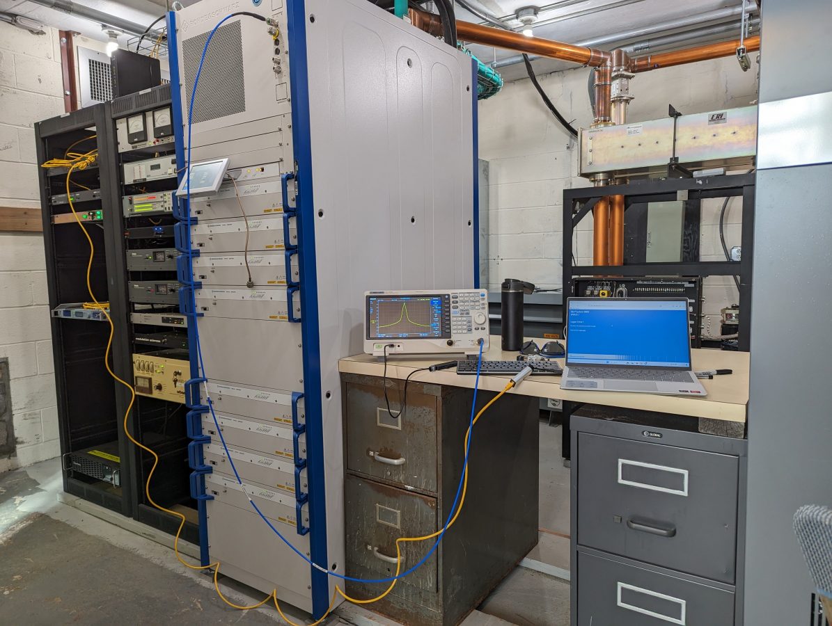
Mark: The analyzer is a Siglent SVA 1023X, which has proven to be a pretty good unit. It is a VNA that will do S11 and S21 measurements, a Spectrum Analyzer, has a Modulation Analyzer and I got the Distance To Fault feature. I have compared it to several other units in the field and it is accurate. I purchased the cal kit, cables, a hard carrying case, an adaptor kit, etc. I think all in it was about $5.5K
Aaron: I agree with everything you said.
Paul and Aaron: Thanks for the info. I forgot the age of these units! Not surprised with the power supply problems. They’re the Achilles heel of more than just transmitters now a days.