HF VHF receiver diplexer

UPDATE and bump:  This post is from eleven years ago, but I have been working on an SDR project using one of the RTL- 2832 chips.  I had to make two more of these units, so the prices and part numbers have been updated.

I have acquired one of those broad-banded software-defined radios, an Icom PCR-1000 to be precise, and all is well.  I am enjoying listening to various MF, HF and VHF radio stations.  However, there is a slight problem.  Very slight, almost too small to even mention, more of an inconvenience than a problem.  Still, if I am being inconvenienced, then others are too.  This issue is with the antennas.  My K9AY antenna works wonderfully from 500 KHz to 25 MHz or so.  My discone antenna works wonderfully from about 30 MHz all the way up to about 1 GHz.  In order to enjoy the full range of the receiver, I need to switch antennas.  I have a small switch on my desktop, but it seems inconvenient to reach over and switch it when going from the AM band to the FM band or something similar.  Therefore, I have decided that I need an HF/VHF receiver diplexer.  One would think that such hardware is ready-made for such instances.   However, nothing I could find commercially would do the trick.

Thus, since I could not buy one, I decided to build one to add to my collection of receiver doo-dads and nick knacks.  The design is relatively easy, a back-to-back low pass/high pass filter system with a 50-ohm impedance throughout.  Something with a sharp cut-off around 30 MHz or so:
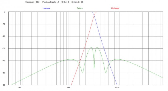
Diplexor plot
Diplexor plot

Looks pretty good, 5th order Chebyshev filter, perhaps .1 dB ripple in the pass bands if well made.  Schematically:
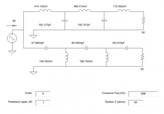
HF VHF diplexor schematic diagram

Then it comes down to the building. Since this is going to be used in the UHF range, care and attention needs to be paid to the layout of the components and the design of the circuit board.  Some of those capacitance values are not standard, however, by using two capacitors in parallel, one can get pretty close.  Since this is going to be used for receiving only, I may be splitting hairs, however, I have found that well-designed and built equipment is worth the extra effort.

The board layout looks like this:
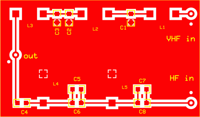
HF VHF receiver diplexer board

I tried to keep the traces as close to 50 Ohm impedance as possible.

As one may be able to discern, C2 and C3 are in parallel to make 192 PF, C5 and C6 are in parallel to make 60 PF, and C7 and C8 are in parallel to make 163 PF.

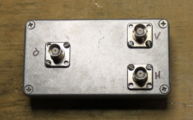
The input and output RF connectors are whatever the builder wants to use, however, I would recommend at least BNC or type N for the VHF/UHF side.  My unit has all type BNC female connectors.   Parts list:

Nomenclature Value Mouser number Cost (USD)
C1 150 PF SMT 581-12065A151FAT2A 0.72
C2 12 PF SMT 581-12061A120JAT2A 0.26
C3 180 PF SMT 810-CGA5C4C0G2J181J 0.27
C4 68 PF SMT 77-VJ1206A680FXACBC 0.59
C5 50 PF SMT 581-12062A500KAT2A 0.41
C6 10 PF SMT 80-C1206C100J2G 0.54
C7 3 PF SMT 581-12061A3R0CAT2A 0.34
C8 160 PF SMT 581-12065A161J 0.34
Case Diecast, 4.3 x 2.3” 546-1590WB 10.71

I chose a smallish, diecast aluminum case, which matches my other receiver gear.  The circuit board noted above is 2.9 x 1.7 inches, which is a little bit small.  I used 18 gauge wire between the input/output connectors and the board.

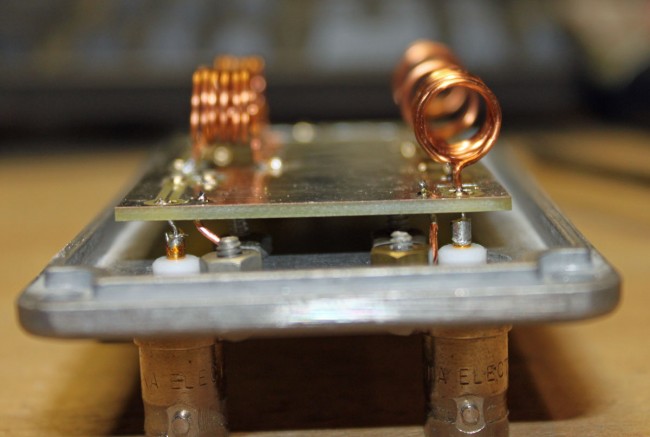
The inductors were made by hand.  I used a small screwdriver as a winding form, making the turns tightly and then spreading them out to the proper distance.

Inductor chart:

Inductor Value (nH) Diameter (mm) Turns Length (mm)
L1 173 8 6 9.5
L2 468 8 10 9.8
L3 414 8 9 8.7
L4 146 8 5 7.2
L5 186 8 6 8.6

The most expensive part was the circuit board, which cost about $16.00.  The rest parts were about $22.00 including shipping.

As built photos:
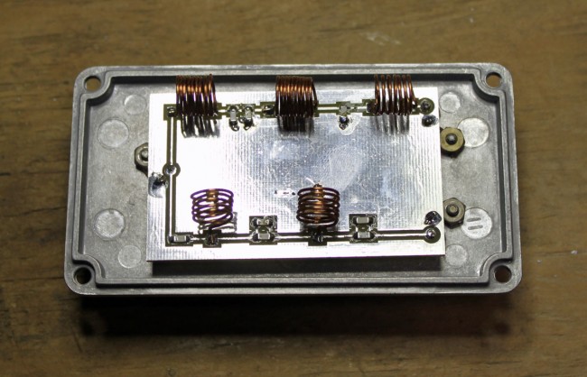
HF VHF diplexor with components installed
HF VHF diplexer with components installed
HF VHF diplexer input side
HF VHF diplexer completed.

I have installed this already and it works great. I will need to get the spectrum analyzer out and run some signals through the various ports to see the attenuation and 3 dB roll-off points.

Making a notch filter

One small RF project that I am working on; a 770 KHz notch filter. I always figure if I am having this problem, then others may be having it too. This is a relatively simple idea, a resonant LC circuit (AKA a tank circuit) tuned to the carrier frequency. It should have a bandwidth of +/- 15 KHz of the design frequency. Another requirement; use the parts I have available. Finally, the environment in which this is to be used is a high-noise room; with lots of computers, LED lights, etc therefore it needs to have excellent RF shielding.

Something like this would work well for anyone that lives around an AM transmitter site and is having problems with receiver sensitivity or transmitter intermodulation.

The basic design looks like this:

Parallel LC tank circuit

Time for a trip to the local storage facility known as “The Barn.” In my backyard, there is a small agricultural structure that is used for storage of just about everything. In The Barn, I found several parts salvaged from an old Energy Onyx Pulsar AM transmitter. As such, they are more than capable of receiver operation and could likely handle a fair amount of RF power in the transmit mode.

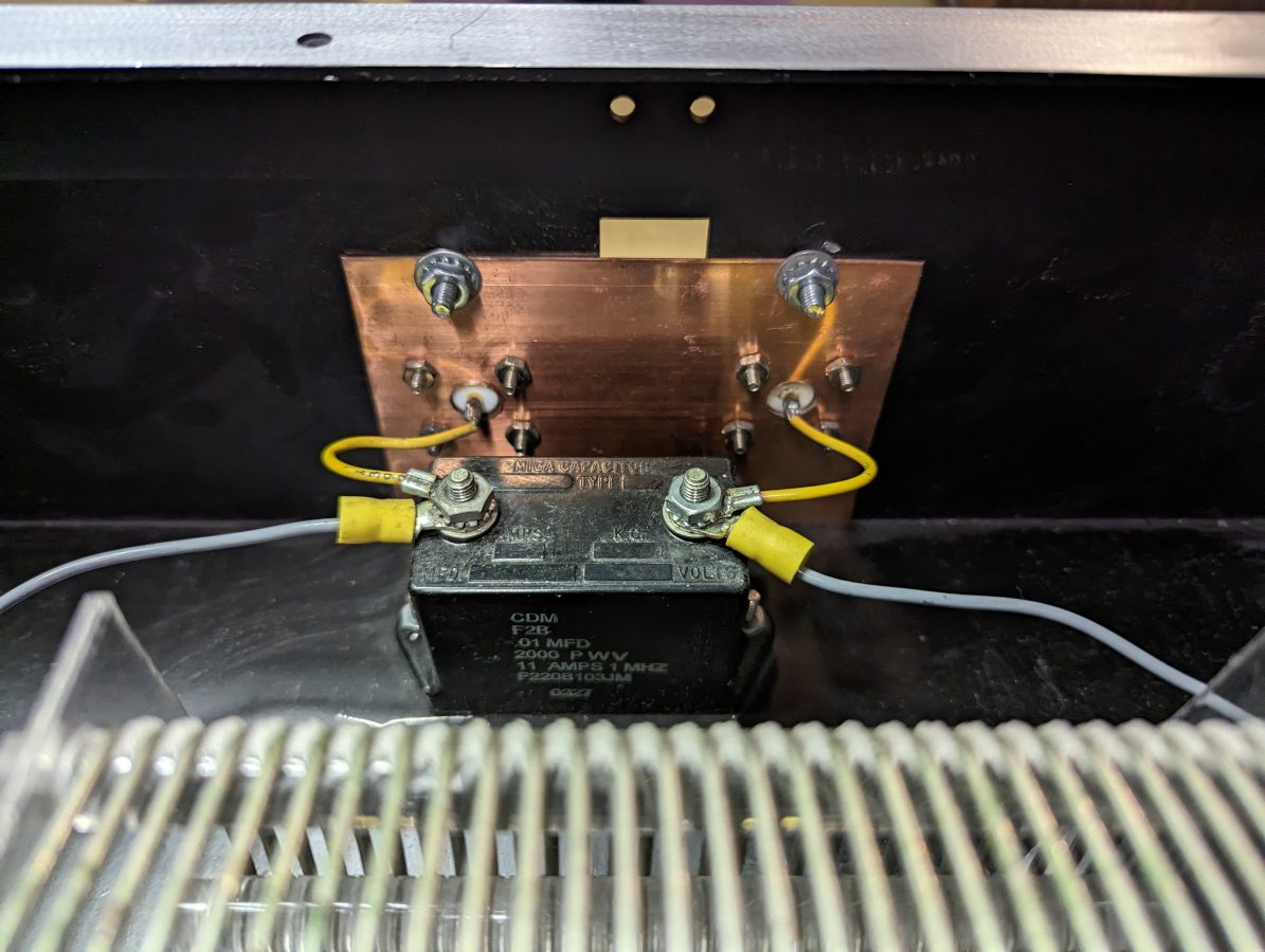
CDM F2B 0.01 uF capacitor with back of N connector inputs

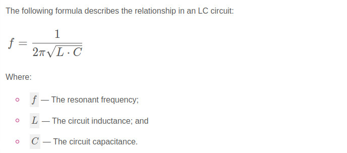
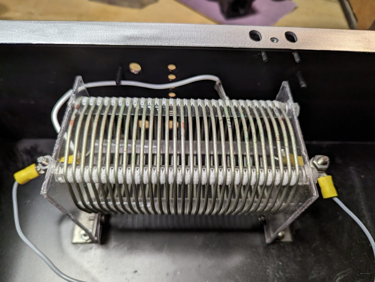
Finding a type F2B 0.01 uF capacitor, rated at 2000 volts and 11 amps, the value of the inductor was calculated. For the inductor, a 20 uH coil with taps will work great. For receive-only applications, much smaller-sized components can be chosen. Also, there are many bandstop filters with multiple poles. Those are great, but I like the simplicity of the parallel resonant LC circuit.

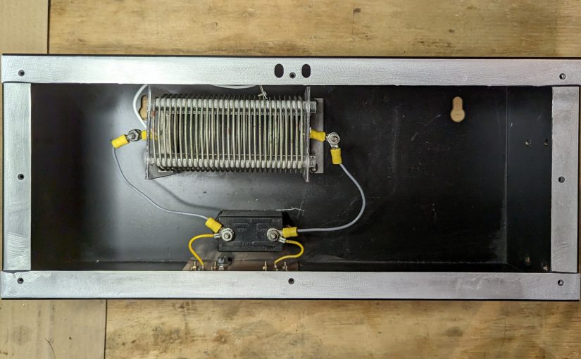
20 uH inductor salvaged from Energy Onyx transmitter

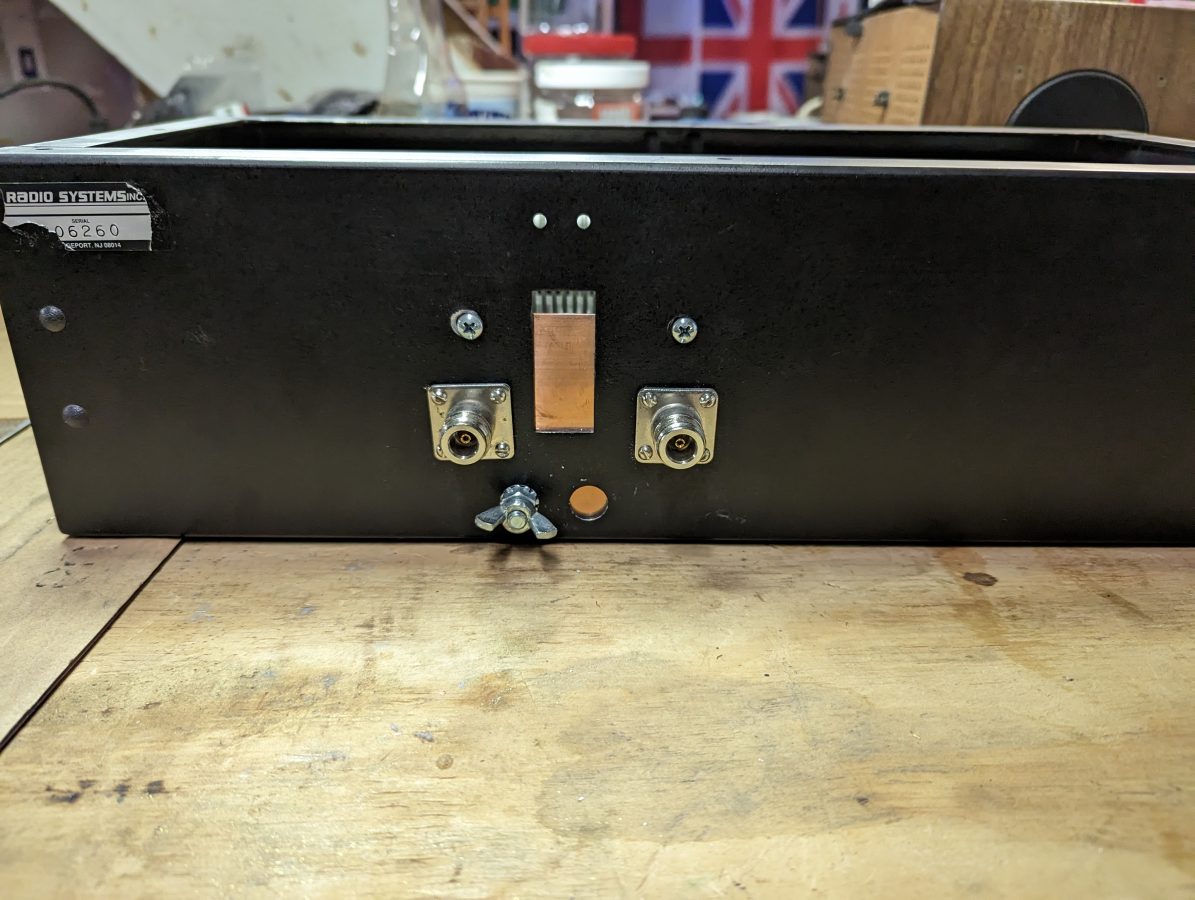
The N connectors were salvaged from I don’t know where and the enclosure used to house a power supply for a Radio Systems console.

N connectors for input and output.

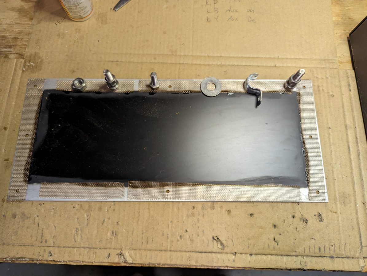
For shielding, I sanded the paint off of the enclosure where the lid is attached and tacked some brass screen down with gorilla glue. This will make a good RF contact surface. The outer of the N connectors are bonded to a piece of copper ground strap which also has a grounding lug on it.

Enclosure lid with brass screen to make contact

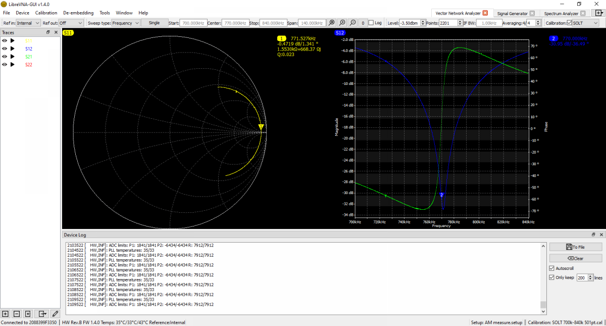
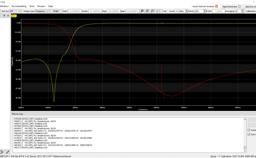
I used the Libra VNA to tune it up:

S12 shows return loss, S21 shows Phase

The scan shows it is -31 dB on the carrier frequency. It is -17 dB on 760 KHz and -20 dB on 780 KHz. This is good, because I may still want to listen to the station on the remote receiver. According to the smith chart, it is actually resonant on 771.5 KHz, but that is close enough for this application. I think the resonance went up slightly when I put the cover on after the tune-up.

There are several tank circuit calculators online. It is best to have more capacitance and less inductance to keep the Q of the circuit low and suppress the sidebands as well as the carrier.

Resurrection of a different sort

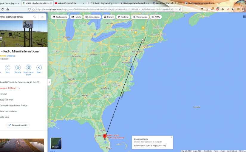
I just finished a full alignment of my Kenwood R-2000 receiver and tonight I am treated with the pleasing tones of “Jazz from the Left,” on WRMI. Jazz from the left means the west coast sound, aka Smooth Jazz as I am given to understand. I spent some time on the west coast and beyond. I have fond memories of those years.

It is amazing to me still, that a simple AM receiver demodulating +/- 4.5 Khz audio bandwidth from 1,057 miles (1701 km) away can sound that good. That is being received directly; no Internet Service Provider, no satellite service, just a transmitter, and a receiver.

There is an art to all this, which is being forgotten. A few minutes with a manual, a volt meter, a tone generator, and a non-conductive screwdriver can bring something that was neglected back to life sounding as good as the day it left the factory 35 years ago. Try that with your very expensive iPhone 10,000,000x! Of course, you will need those tiny pentalobe tools to get the screws out. Apple would rather you return your expensive i device to their expensive i store so that their i geniuses can fix it for you.

I don’t know, maybe I am an old fart. Perhaps the right to repair the appliances that I purchased and therefore should own is an old-fashioned point of view. After all, all of these corporations have my best interests at heart, right?

I recommend you support your not-so-local shortwave stations by listening to and supporting their programmers. Even in 2021, there are still many shortwave broadcasts that are worth listening to!

WYFR shortwave signing off

Family Radio’s WYFR shortwave service will be ending on June 30, 2013.

WYFR 50 years
WYFR 50 years

Shortwave transmitting is very expensive, and no doubt, competing IP distribution technology and diminishing returns on such investment must play a factor in this decision.  Family radio has been struggling ever since the world did not end as predicted in 2011.

I believe that site has fourteen 100KW HF transmitters and eighteen antennas of various type.  There is a complete photo album here: https://picasaweb.google.com/115519153277489147905/WYFR?noredirect=1#5149450014785168130 courtesy of Kent.

Kind of sad to see them go, I don’t know what their plans are after June 30.