GPS controlled clock based on Raspberry Pi

This is an adjunct to my previous post on creating a Stratum 1 NTP time server with a Raspberry Pi. I finished this project about a year ago, and I have to say it has been running flawlessly since then. I thought that perhaps the inexpensive GPS module designed to work with drones might not hold up. But it has.

Midnight in London

Wouldn’t it be nice to use this time source, not just to set hardware clocks but also display the time in varous places? Yes, yes it would.

Since most of my ideas are not original, I figured a quick internet search may shed some light on how to proceed. Keith, G6NHU did exactly this a year ago or so. His project can be viewed here: https://qso365.co.uk/2023/05/how-to-build-a-shack-clock-using-a-raspberry-pi-and-a-7-touch-display/

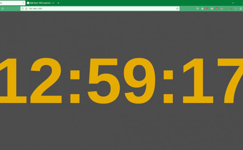
As I suspected, with a few more configuration steps, this NTP server can display the time on the native HDMI port as well as create a simple web page available on the LAN for any computer to access with a web browser. The web server is Lighttpd, which is a low CPU load, low memory demon, perfect for an older Raspberry Pi 3.

The display I chose is a 7-inch 16×9 non-touch purchased from Amazon for $33.99: https://www.amazon.com/gp/product/B0BGXB2Y67/ (not an affiliate link)

When I created the NTP server last year, I named it ntpserver. The unit runs headless (no keyboard or monitor) so I use ssh to get into the command line. Thus, the first command is:

ssh ntpserver@192.168.1.200

Once in, always do an update:

sudo apt-get update
sudo apt-get upgrade -y

The following programs need to be added to the Pi:

sudo apt install xorg openbox xserver-xorg xinit unclutter lighttpd -y

If the OS is off the shelf Raspian, then Chromium should already be installed, but if not, then add it:

sudo apt install chromium-browser -y

Once that is done, some things need to be configured. Using whatever text editor you like the xserver so that anyone can access it. Open the Xwrapper file:

sudo nano /etc/X11/Xwrapper.config

Then add line:

allowed_users=anybody

Exit and save. Next open the xserverrc file:

sudo nano /home/ntpserver/.xserverrc

Add the following:

#!/bin/sh
#Start the X server session with no power management so the display never sleeps
exec /usr/bin/X -s 0 -dpms -nolisten tcp "$@"

Exit and save. Next open the xsession file:

sudo nano /home/ntpserver/.xsession

Add the following:

#!/bin/sh
#Start Chromium at startup
chromium-browser --start-fullscreen --window-size=800,480 --disable-infobars --noerrdialogs --incognito --kiosk http://localhost

Exit and save. Note the display size can be configured to any screen resolution. This affects the HDMI port, not the web page. The 7-inch Raspberry Pi monitor that I purchased from Amazon has an 800 x 480 screen resolution. If you are using a different screen resolution, change as needed. Next open the clock.service file (it will be created when you save the file):

sudo nano /etc/systemd/system/clock.service

Add the following:

[Unit]
Description=Clock
After=network-online.target
DefaultDependencies=no

[Service]
User=clock
ExecStart=/usr/bin/startx
Restart=always
RestartSec=10

[Install]
WantedBy=multi-user.target

Exit and save.

The web page that will be displayed on the HDMI port as well as served to local hosts on the LAN is a java script page. It was originally developed by Nayuki: https://www.nayuki.io/page/full-screen-clock-javascript You can download whatever format you like from that site (I copied the page source) or you can download a 24-hour format from Keith’s site:

cd /var/www/html
sudo wget https://qsl.net/g6nhu/clock/index.html

The colors can be edited:

sudo nano /var/www/html/index.html

The background, foreground, and font type can be changed as desired.

Next start the clock service and reboot:

sudo systemctl enable clock
sudo systemctl start clock
sudo reboot now

Here is a quick video of the web page on my desktop computer. I have the GPS monitor from the ntpserver up and running in the left upper corner. That shows the GPS data going into the Raspberry Pi from the serial port along with some scratchy WWV audio. The actual clock sync is from the 1PPS output of the GPS module.

I could see this being used as an inexpensive master clock system somewhere. With an HDMI splitter (or a better name would be Distribution Amp), this could be sent to many locations.

Now all I need to do is figure out how to get a GPS synced 10 MHz output capable of driving multiple devices.

What time is it?

This is an important question these days. We are running into more situations where timing is important, especially when audio and video codecs are concerned. If there is too much time differential, the codec will unlock. More often, digital transmission methods require precise timing to prevent jitter and dropouts. Some equipment has 10 MHz or 1PPS inputs. Some equipment does not and relies on NTP to keep things in sync.

While searching online for GPS time sever, I came across this post where Austin built a Stratum 1 level time sever with a Raspberry pi and an inexpensive GPS receiver. I thought to myself; damn that sounds interesting. While a Raspberry pi is a hobbyist toy, the same setup can be done with a more serious computer to create a solid NTP server for a facility or LAN.

A little about NTP time servers; Stratum 0 server is directly connected to an atomic clock. Since GPS satellites have atomic clocks, that makes them a Stratum 0 server. Stratum 1 servers are connected to Stratum 0 servers. Stratum 2 servers are connected to Stratum 1 servers and so on. The time accuracy for a Stratum 1 server is 10 microseconds.

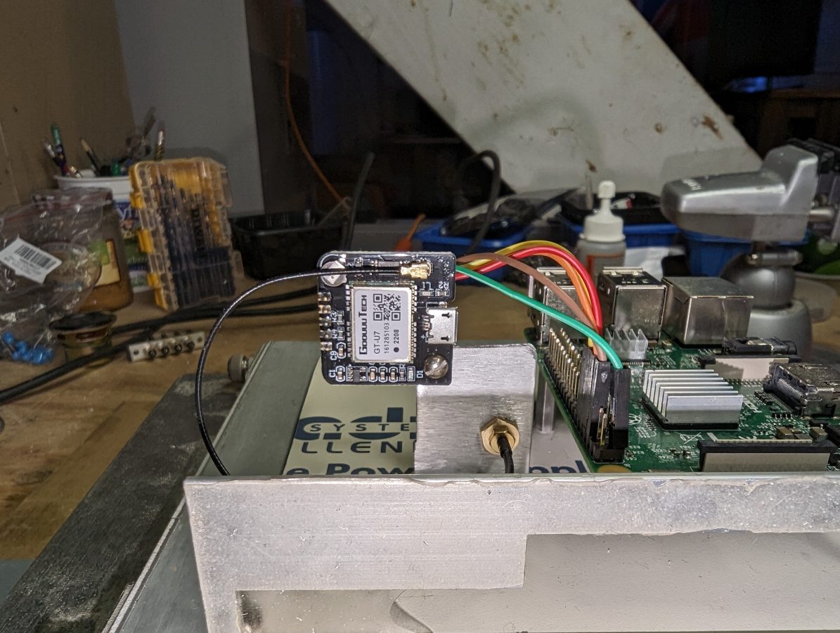
First, I wiped my SD card and loaded a fresh install of Raspberry pi OS. Then followed along with the instructions. For this install, I opted for the cheaper GPS receiver, the GT-U7 (not an affiliate link) from Amazon for $10.99. It comes with a cheap little antenna, which actually worked sitting inside on my desktop while I was configuring the software.

This little module is designed for a drone but works well in this application. The 1PPS output looks clean on the scope. Here is the pinout between the GT-U7 and the Raspberry pi:

GT-U7 pinpi pinUseColor
vcc1+3.3 vdcGreen
gnd6groundBrown
txd8rxdOrange
rxd10txdRed
pps12GPIO 18Yellow

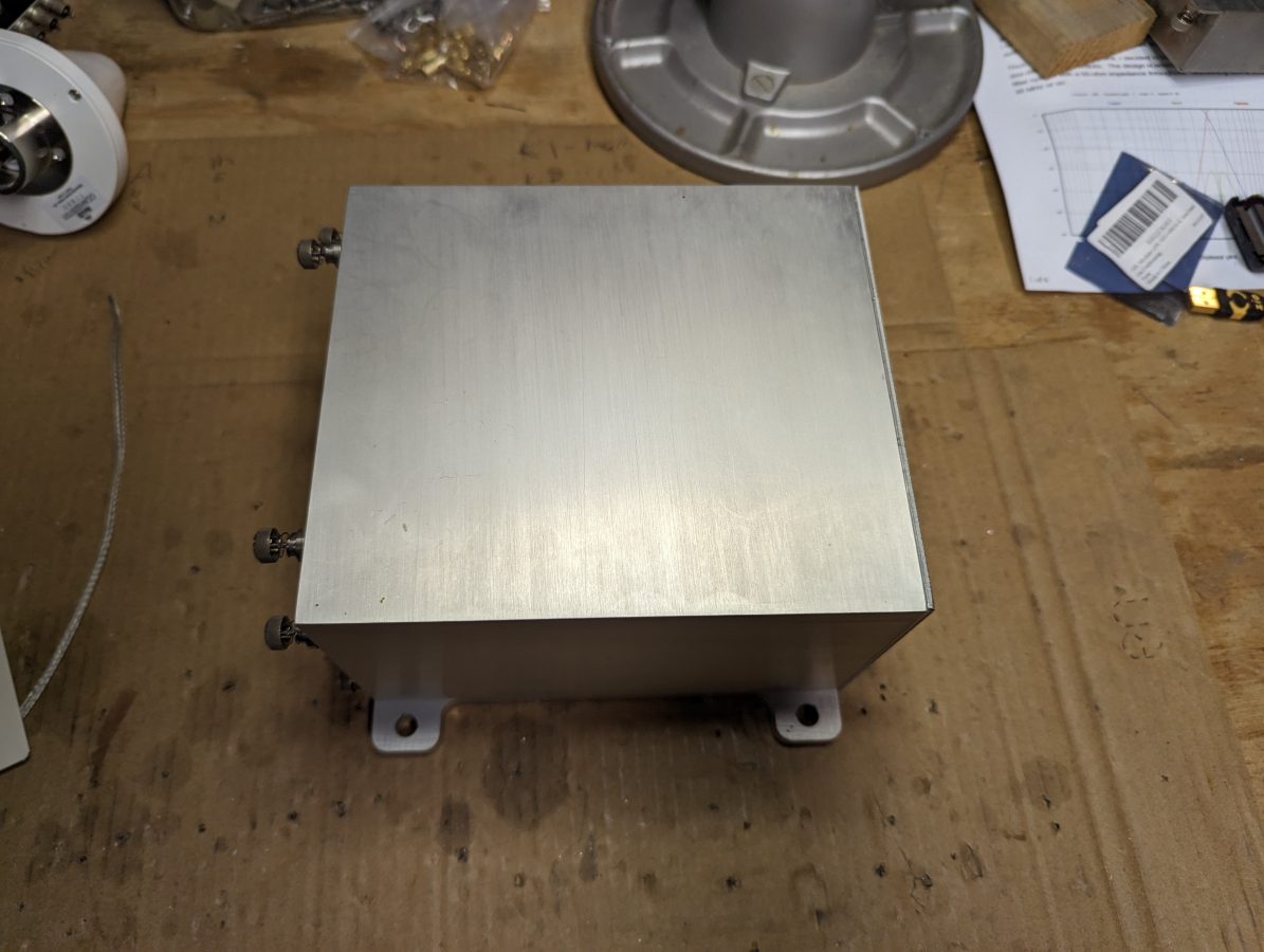
I found this really nice aluminum case in a pile of disused junk at a transmitter site. It used to be for a digital TELCO STL circuit. I figured it would be nice to put the Raspberry pi and GPS receiver in a suitable home.

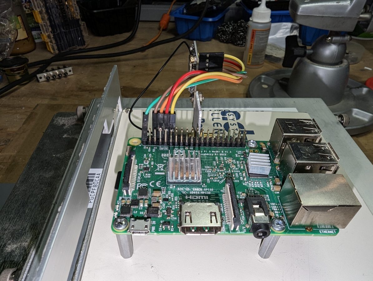
Raspberry pi 3 is mounted on a piece of scrap sheet steel designed to slide into the aluminum case.

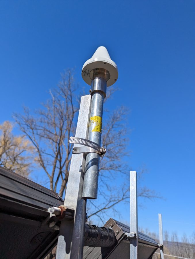
We have several of these nice Panasonic GPS antennas left over from various installs. I pressed one into service on the roof of my house.

Panasonic CCAH32ST01 GPS antenna

I think a high-quality antenna is pretty important to get consistent good performance from this setup. There are three slight problems, however. Unfortunately, this antenna has been discontinued by the manufacturer. Also unfortunate, the GT-7U boards have one of those little IPX RF connectors. Fortunately, I found a short jumper with an F SMA connector. Finally, it requires +5 VDC and the GT-7U runs on 3.3 VDC. The pi does have a 5-volt rail, so I used this 2-way power divider to feed 5 volts to the antenna from one port and the received RF from the antenna goes to the GT-U7 from the other port.

If you are interested, here are the commands to get this thing running:

sudo apt get update
sudo apt get upgrade -y
sudo apt install pps-tools gpsd gpsd-clients chrony

The next step is to make sure the serial port is turned on and enable the ssh login shell since this is going to live in the basement and I don’t want to run down there to fool around with it.

sudo raspi-config

Then go to interface options, serial interface, and enable. The login over the serial interface can be left off. If ssh access is needed, enable ssh, then exit.

Once those packages have been downloaded and installed, some config file editing is needed. You may use whichever method you like, I tend to use nano. First, the /etc/config.txt and add the following to the file:

‘dtoverlay=pps-gpio,gpiopin=18’
'enable_uart=1'
'init_uart_baud=9600'

The uart needs to be enabled if you want to receive NMEA data (NMEA stands for National Marine Electronics Association) It is helpful to see if or how the GPS is working.

Next, the /etc/modules and add:

'pps-gpio'

Reboot, then see if the pps module is working:

lsmod | grep pps

The output should look like this:

Next, there are a few more configuration files that need to be edited.

/ect/default/gpsd – there is a default file that comes with the package, it needs to be modified to start the daemon automatically and look for the pps signal on ttyS0.

START_DAEMON="true"
USBAUTO="true"
DEVICES="/dev/ttyS0 /dev/pps0"
GPSD_OPTIONS="-n"

Reboot

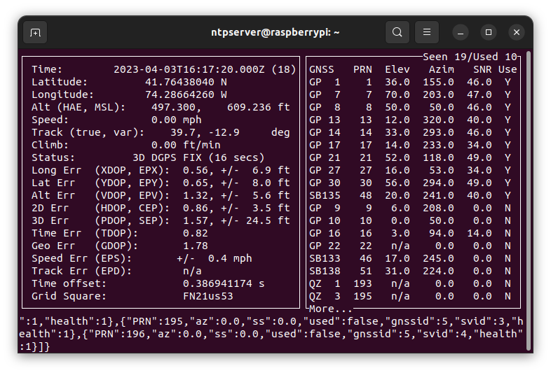
Now check and see if the GPS module is working by typing cgps or gpsmon. The output should look something like this:

It did not take the module too long to find and lock onto GPS. If you don’t see something like this in five minutes or so, go back and check your wiring, and make sure that the data connections are made right. The GT-U7 has a little red LED that is lit when the PPS pulse is not being sent. If this light is not on at all, check your power connection. If it is on steady, check your antenna. If it is flashing, but you are not seeing any output in cgps or gpsmon, check your data connections.

Next and last configuration file is the /etc/chrony/chrony.conf file. At the top of the file, I added the following lines:

#custom lines for PPS
server time-a-g.nist.gov iburst
server time-d-g.nist.gov
server 3.us.pool.ntp.org
server time.windows.com
server time.apple.com
# add refclock pps
refclock SMH 0 delay .1 refid NEMA
refclock PPS /dev/pps0 refid PPS
#my home network
allow 192.168.1.0/24

Leave the rest of the file alone. Basically, the time servers are added to compare the GPS time and act as a backup. The hosts on my home network are allowed to query this host and use it as an NTP server.

Restart Chrony:

sudo systemctl restart chrony

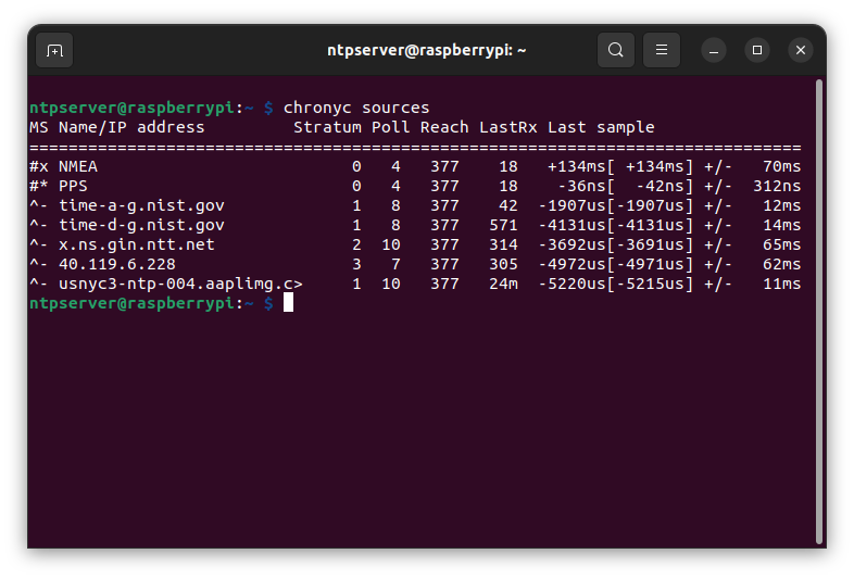
Wait a couple of minutes and check the chrony console to see what is happening: chronyc sources. Should look something like this:

This was after the server had been running for a day. Chrony is great because it measures the hardware performance and creates a delay file. This is used to anticipate any hardware-added delays that the system might have. The last sample column is of interest, the number indicates the offset between the local clock and the source at the last measurement. The far column is the margin of error or greatest variation +/- of the expected values. A value of 0.0000000042 seconds or 0.042 microseconds is pretty good for an $11.00 piece of hardware. Now every host in my house is syncd to satellite within 0.042 microseconds, in lockstep through the time-space continuum.

If I were to do this professionally, I would use better hardware. I think the pi 4 has better serial and ethernet interfaces, more RAM, and a quad-core processor. Last I looked they were $75.00 at Newark.

The GPS module was the cheapest I could find on Amazon. I am slightly concerned about the longevity of this device. Perhaps it will run for a long time, or perhaps not. A quick search brought up several “hats” (plug directly into the 20-pin header). These range in price from about $30.00 to $60.00. What is required of any GPS module is 1PPS output. The configuration would be about the same although some use GPIO 4 instead of 18.

Distributed Mode Loudspeakers

My journey into home stereo speakers and high-quality audio continues…

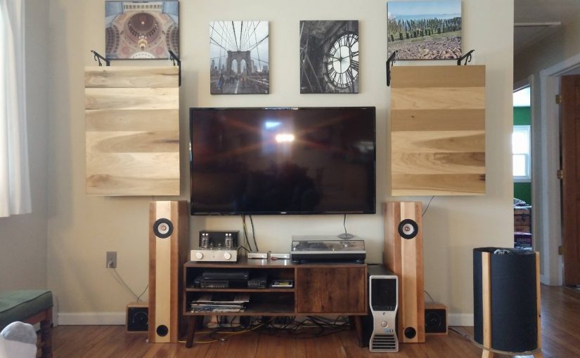
This is not a broadcast-related post, but I find this type of thing interesting nonetheless. A few years ago, I began fiddling around with flat panel speakers or Distributed Mode Loudspeakers (DML). My first attempt was lackluster, although adequate and not very expensive.

I enjoy listening to all types of music. I notice that some music reproduces better than others. The piano is a particularly difficult instrument to record and faithfully reproduce because of the complexity of the instrument itself. It is a percussive string instrument. When one of the hammers strikes a sting, the string itself does not make a very loud noise. The string is connected to a soundboard through a bridge. The much larger soundboard vibrates and amplifies the initial sound. Thus, the wood itself imparts a noticeable quality to the sound. Several other instruments such as acoustic guitar, violin, etc also use tonewood to amplify sound. Thus, when listening to a piano being played back on a set of speakers, it lacks much of the original texture of the actual instrument. It sounds like a recording of a piano, not an actual piano.

This made me think of ways to improve that reproduction.

A DML uses a large flat surface to reproduce sound. The large surface area and the bi-directional nature of the panel means the sound will be defused and not directional as is the case with conventional speakers at higher frequencies.

The principal characteristics of the material used in a DML are stiffness and density. The less dense (lightweight) and the stiffer the better. All materials have internal resonances, some decay quickly and others, such as steel will ring for a long time. A ringing reverb sound would be undesirable in most cases. Tonewood has suitable stiffness and a relatively high sound radiation coefficient that varies in density according to species and generally dampens high-frequency harmonics. Pianos often use Sitka Spruce for soundboards.

I made two terminated transmission line speakers last summer. Those sound great, but using one driver to reproduce all sound from 20-20,000 Hz has a drawback; the high-end lacks detail and is very directional.

A bit of research shows that Poplar has good to very good tonewood qualities while being inexpensive and readily available at the local big box hardware store. Thus, I purchased several 1/4 x 6 x 48 inch (6 x 152 x 1220 mm) planks and a few pieces for bracing to make two 33 x 22 inch (838 x 559 mm) flat panels. The idea here is to gently cross over the transmission line speakers at 4,500 Hz with these flat panels.

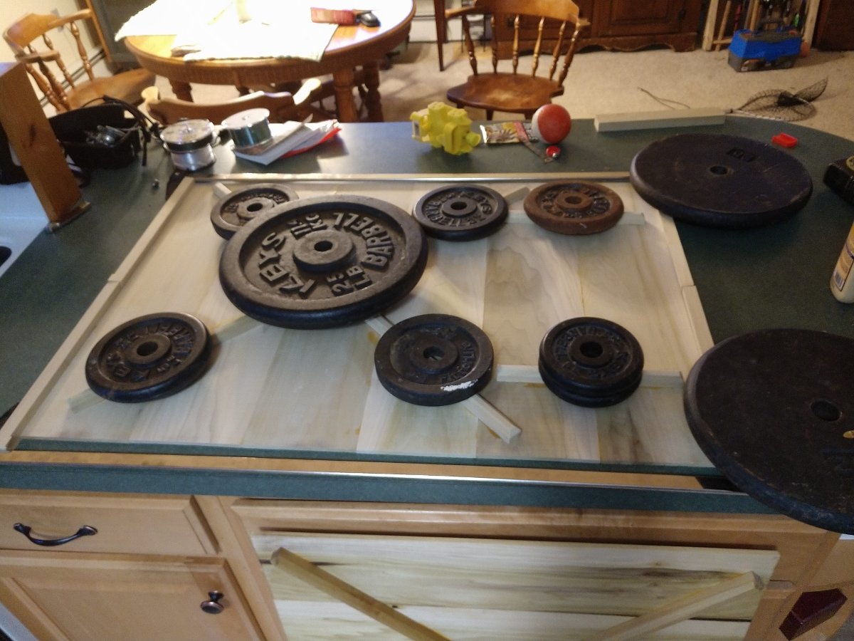
The assembly process was pretty easy. It took perhaps two hours to cut all the pieces to the right size. I used a router to chamfer the edges of the back bracing, mostly to reduce the weight of the brace. Everything was glued up and allowed to dry for 24 hours.

Gluing the parts together
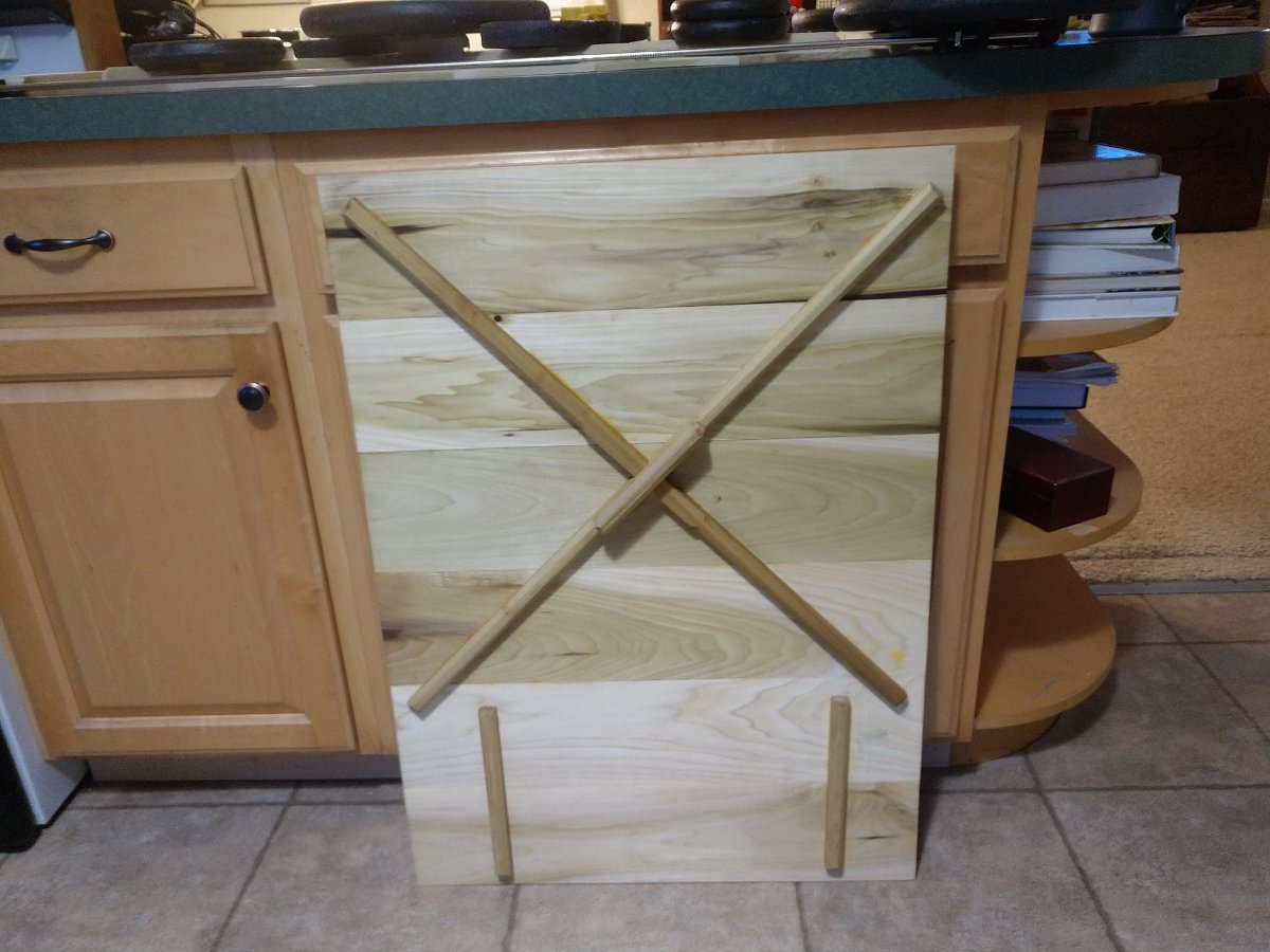
Back bracing

The bracing is designed to keep the panel stiff and helps with structural integrity. I sanded the fronts and backs of the panels, then finished them with Tung Oil.

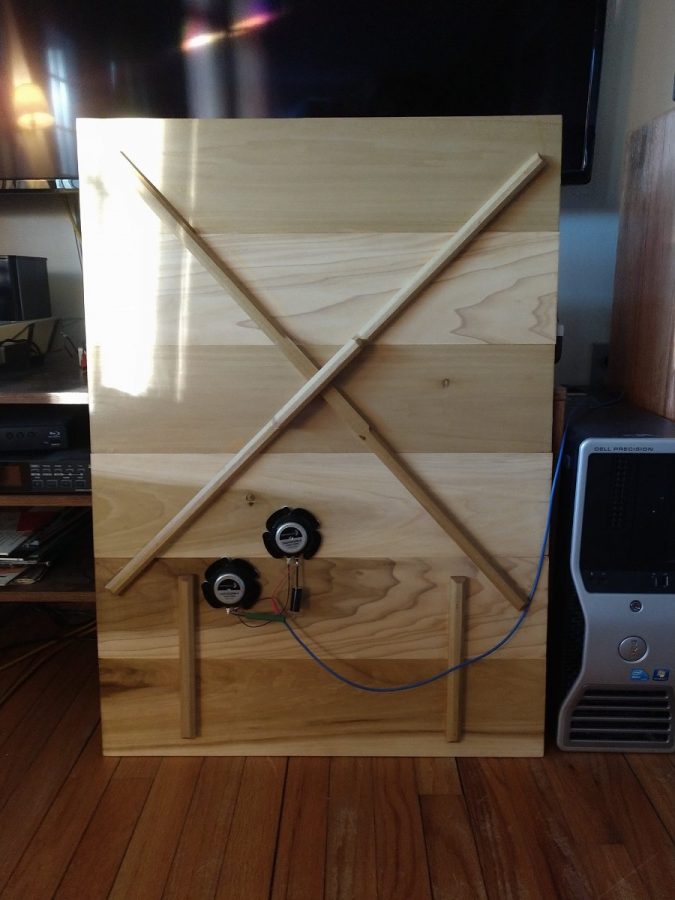
Dayton tactile exciters

Each panel uses two Dayton DAEX32QMB-4 tactile exciters wired in series. There is also a Zobel network which is important for a tube amp. Most drivers’ impedance will rise as the frequency increases. This rising impedance is mostly reactance from the driver coil. For solid-state amps, this is not much of a problem. However, tube amps, because of the output transformer, need a fairly constant impedance across their output range. This is because the output transformer is a ratio device. The primary impedance is derived from the impedance on the secondary (e.g. what the secondary is terminated with). For example, a certain tube has a 5,000-ohm plate impedance. The output transformer is chosen to match this design specification. The output transformer is designed to drive an 8-ohm loudspeaker. However, the driver impedance rises to 16 ohms at 15 KHz and 24 Ohms at 20 KHz. Under those conditions, the tube would be seeing a 10,000-ohm impedance at 15 KHz and a 15,000 Ohm impedance at 20 KHz. This will lead to added distortion. The Zobel network keeps the impedance fairly uniform across the entire audio range.

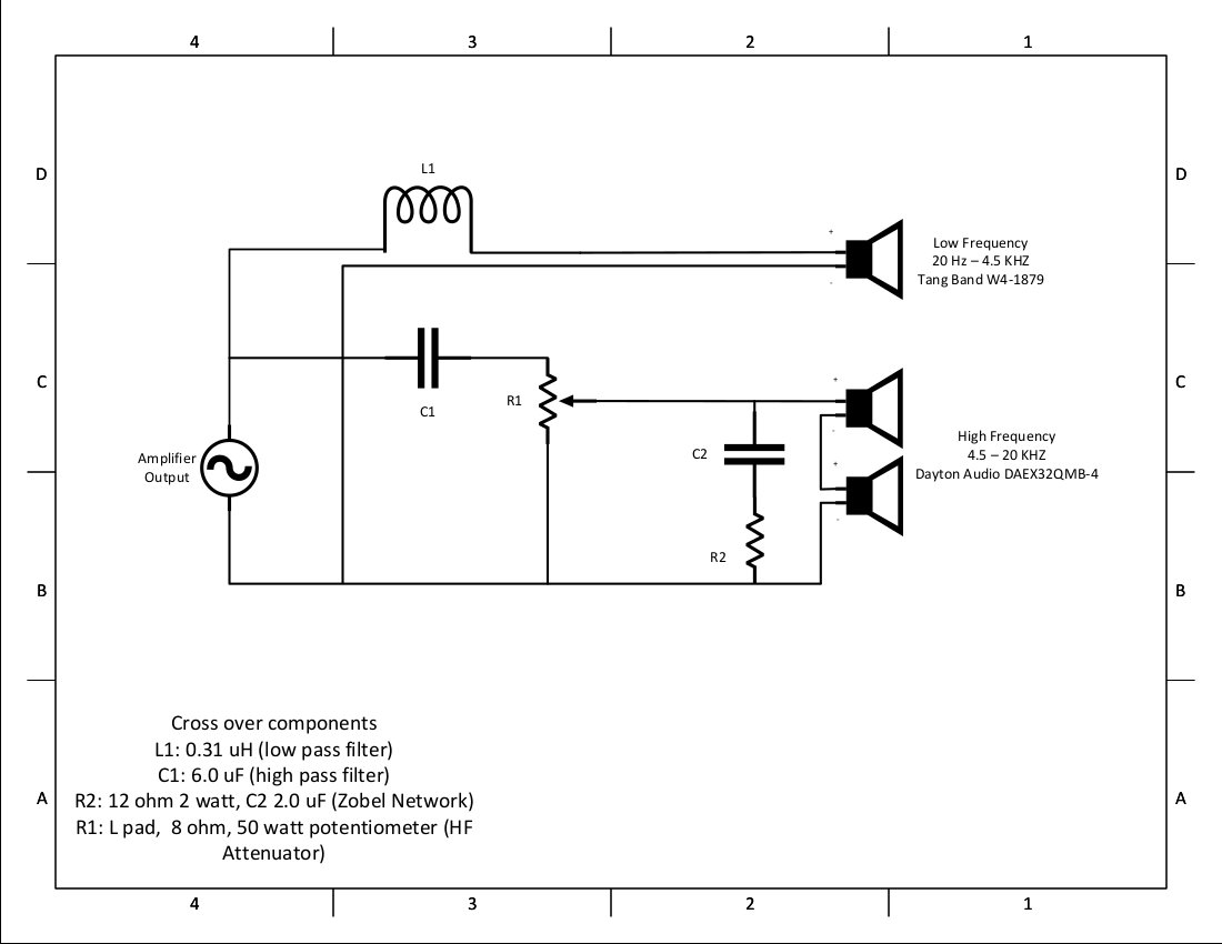
Rather than build a cross-over into the transmission line speakers, I made an external unit. This allows the speaker system components to operate independently if needed. I can easily change the cross-over components for a different crossover point. I can also mix and match things in the future. In other words, it gives me a great deal of flexibility for future projects and experimentation.

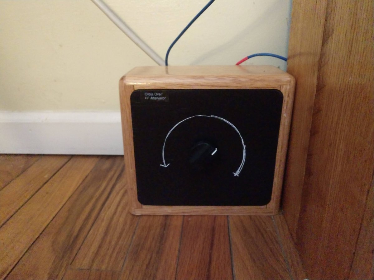
Crossover and HF attenuator
Crossover and attenuator components

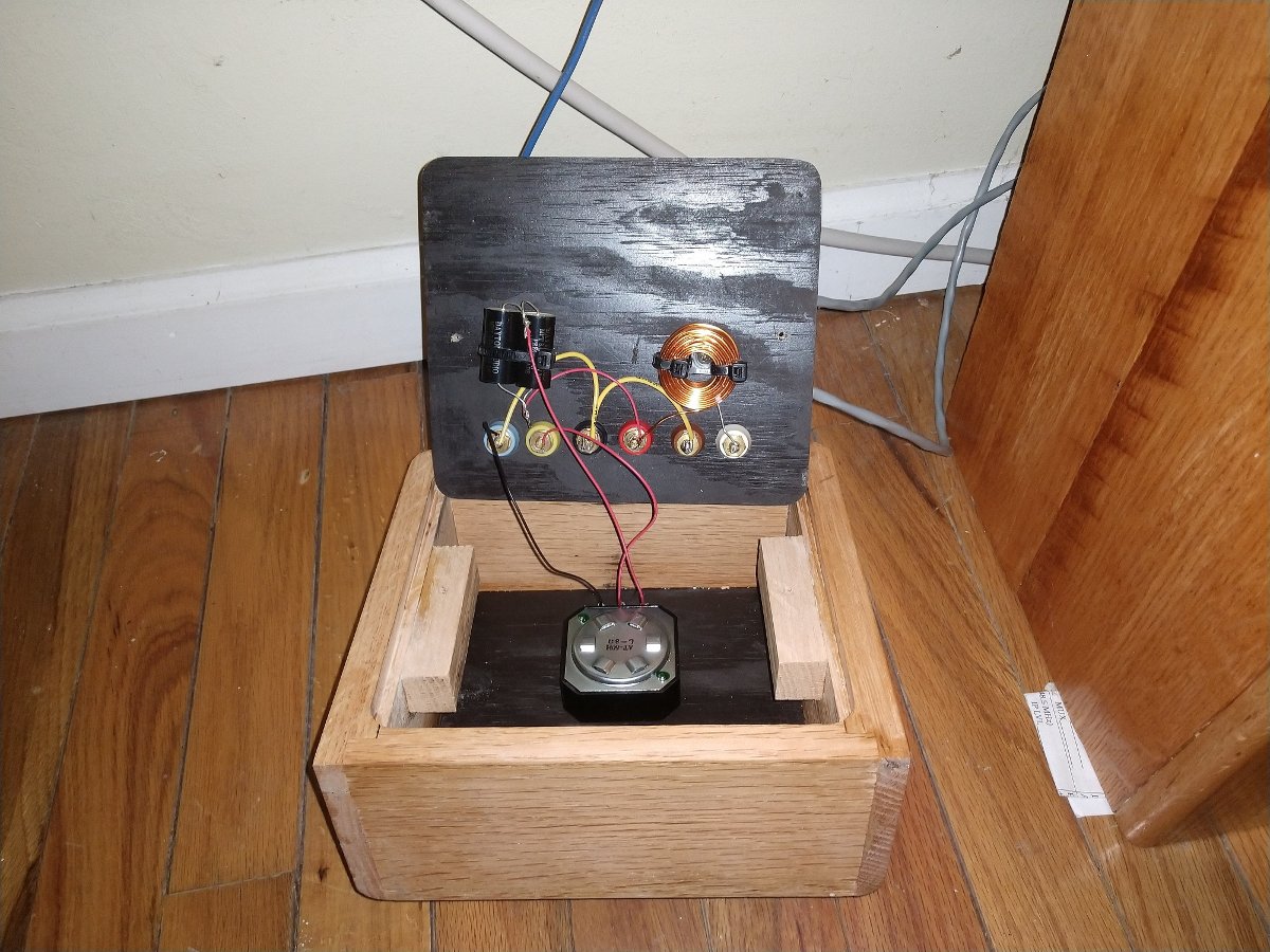
I made these small boxes to match the speakers. These contain the crossover and HF attenuator. The attenuator is necessary because of the difference in efficiency between the transmission line driver and the tactile drivers on the DML.

The schematic looks like this:

Cross over diagram

I kept things as simple as possible. Yes, I could have made a 12 dB per octave crossover with a few additional components, however, I like the gentle blend of both drivers in the mid-ranges.

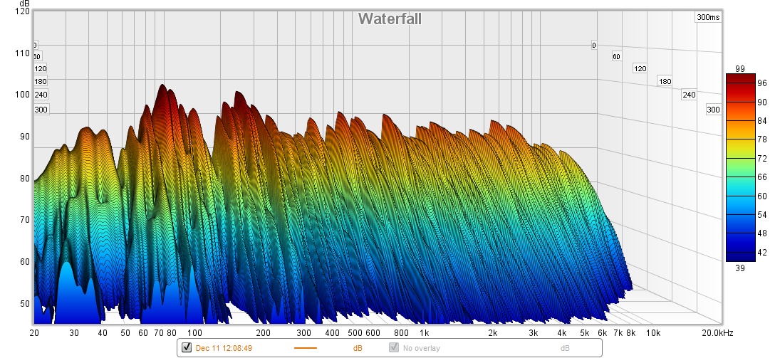
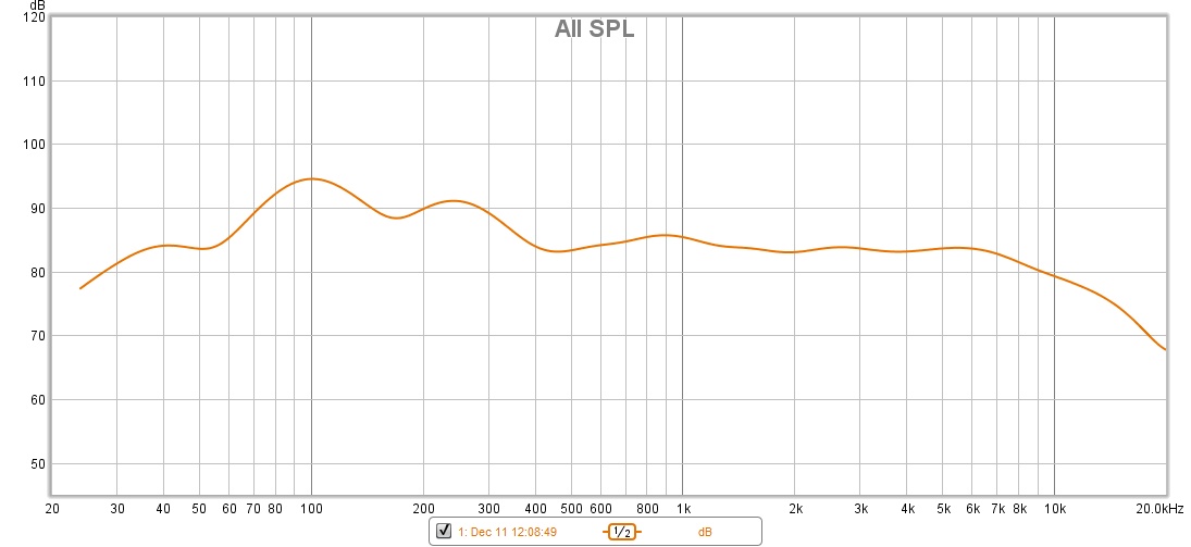
A basic sweep with Room EQ Wizard shows a fairly flat response. There is a room resonance of around 90 Hz which I intend to correct with some sound-deadening materials in the corners and possibly a bass trap.

Room EQ Wizard waterfall display

This shows that the speaker system is relatively flat from about 200 Hz to 10 KHz. Those bumps and dips from 88 to 250 Hz are all room due to room resonance.

Room EQ Wizard SPL graph

How does it sound? Pretty good! Here is some copyright-free music, recorded from youtube, then re-uploaded to youtube! It is not the best video, there is some background noise, etc. However, it gives a pretty good idea of how these sound.

Automation Systems

Radio Automation Systems are nothing new under the sun. As Marconi tapped out his famous S, he was likely thinking “We should get a machine to do this…”

Broadcast stations have been installing different types of automation since the mid-1950s and early 1960s.  It was touted as a way to free up announcers so they could do more important things.

While cleaning out an old studio/transmitter building and getting things ready for demolition, I found a stash of old product brochures for various automation systems from the 60s, 70s, and 80s.  It looks like the previous owner used to go to the NAB every year.  How many radio guys got their start on the overnight shift changing out reels?  I know a few.

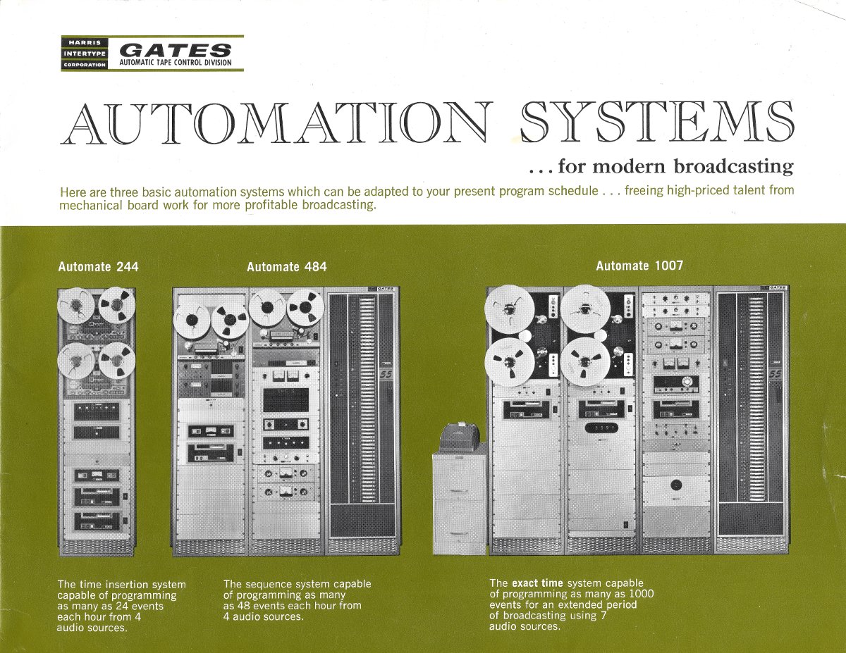
Gates automation system brochure, circa 1965

The Gates Radio Corporation had a fairly standard reel-to-reel system in three different configurations.  These systems were pretty pricey in their day.  According to the 1966 price list:

  • The Automate 244 cost $7,275.00 ($58,837.00 in 2020)
  • The Automate 484 cost $12,210.00 ($102,946.00 in 2020)
  • The Automate 1007 cost $17,150.00 ($138,799.00 in 2020)

Those are for stereo systems, mono systems cost about $500.00 less.  Each one of those systems ran one station.

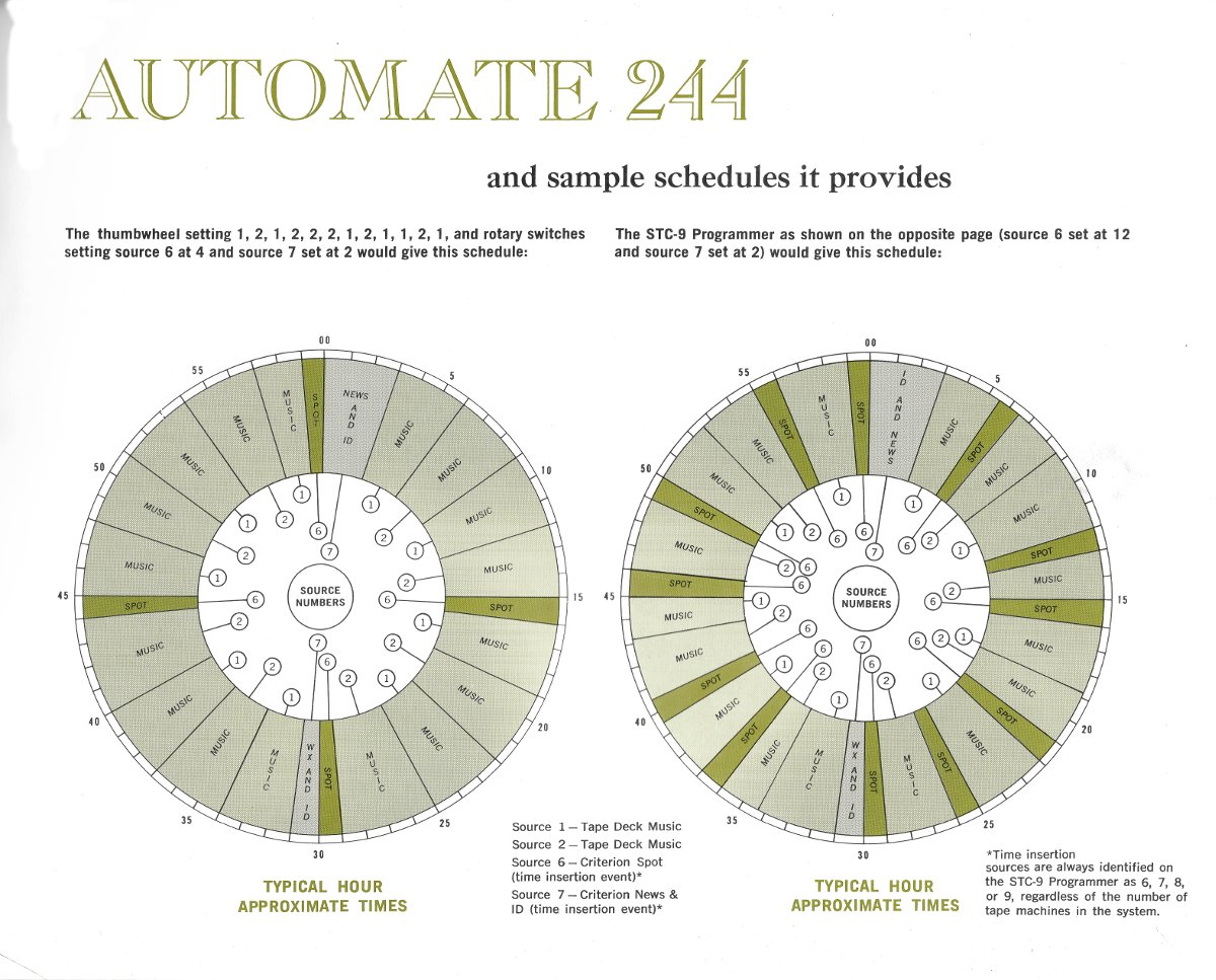
Gates Automate 244 events thumb wheel

The larger the system, the more events it could trigger.  I have never run into one of these in the wild.

Long-form satellite shows began to surface in the early 1980s. Things like all news formats and overnight talk shows.  I have had nightmares where everyone walks around saying “This is Larry King, you’re on…” while UFOs fly overhead and next-door neighbor, Jim Hightower, buries PCBs in his backyard not more than 200 feet from his house.

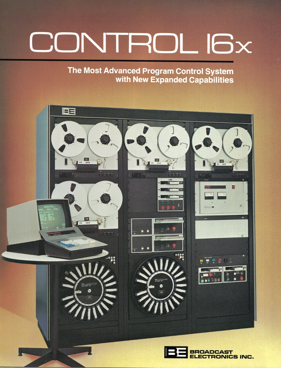
Broadcast Electronics Control 16 radio automation system

Broadcast Electronics had the Control 16 system in the 1980s that ran off of a very basic computer system that could handle 3,000 events with the standard RAM configuration and up to 9,999 events with additional RAM.  This was ideal for multiple program sources; music on reel machines, satellite syndicated talk or music formats, etc.  No longer were these machines simply running the overnights.

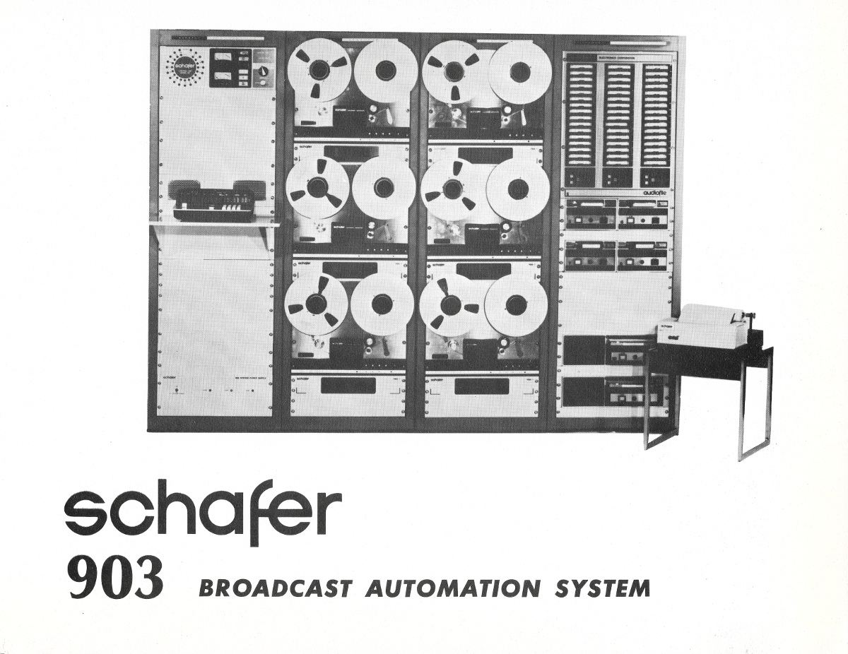
Schaffer 901 radio automation system
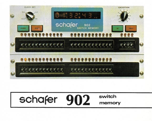
Schafer 90x radio automation system

Schafer is perhaps the most known analog tape automation, at least to me.  I know of several of these systems that were in operation through the mid 1990s.  By this time, long-form satellite music formats had become the rage.  However, there were still a few stations using reel-to-reel music services.

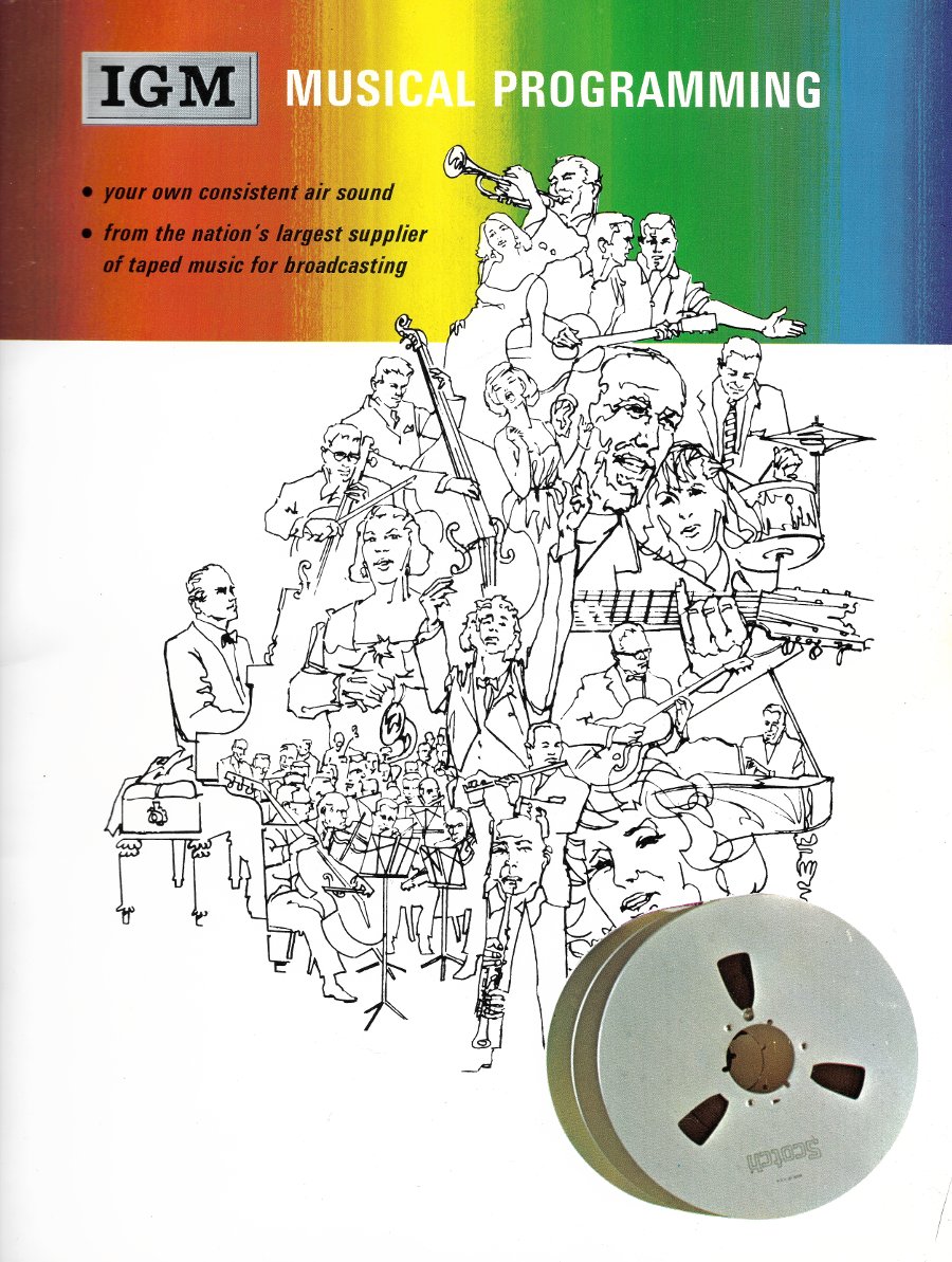
I particularly like this flyer from IGM:

IGM (International Good Music) brochure, circa 1971

By the mid-1990s, these tired old dinosaurs were being removed.  Still, the mechanics of the operation were a thing to behold.  It was nice because you could hear the relays snap shut after decoding a 25/35 Hz tone or one of the Mutual Radio be-doops.  The cart-o-matic would chug through the break until the liner fired and then back to the bird.  If there were any issues, one simply needed to stand there and watch which part of the machine malfunctioned.

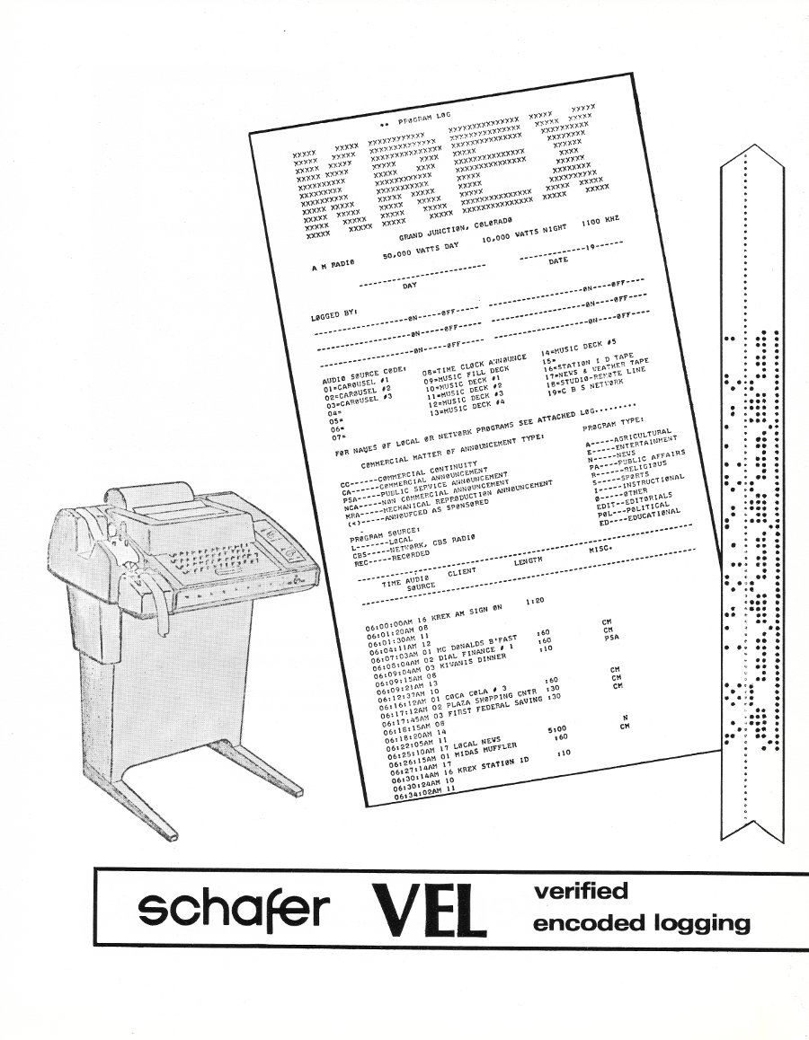
Schaffer logging system
Schafer logging system

Computer-based systems like Computer Concepts DCS, Arrakis Digilink, and Audio Vault came along, which got rid of the analog tape.  Instead, they stored audio on hard drives.  In those early systems hard drive space was a premium, so usually, at least 3:1 compression was needed to fit all the commercials onto the drive space available.

My first brush with Audio Vault was in 1994 at WGY in Schenectady, NY.   It was a pretty good system if you could understand the .ini files.  As the BE tech support guys used to say “You can program it to turn the coffee pot on if you wanted to.”

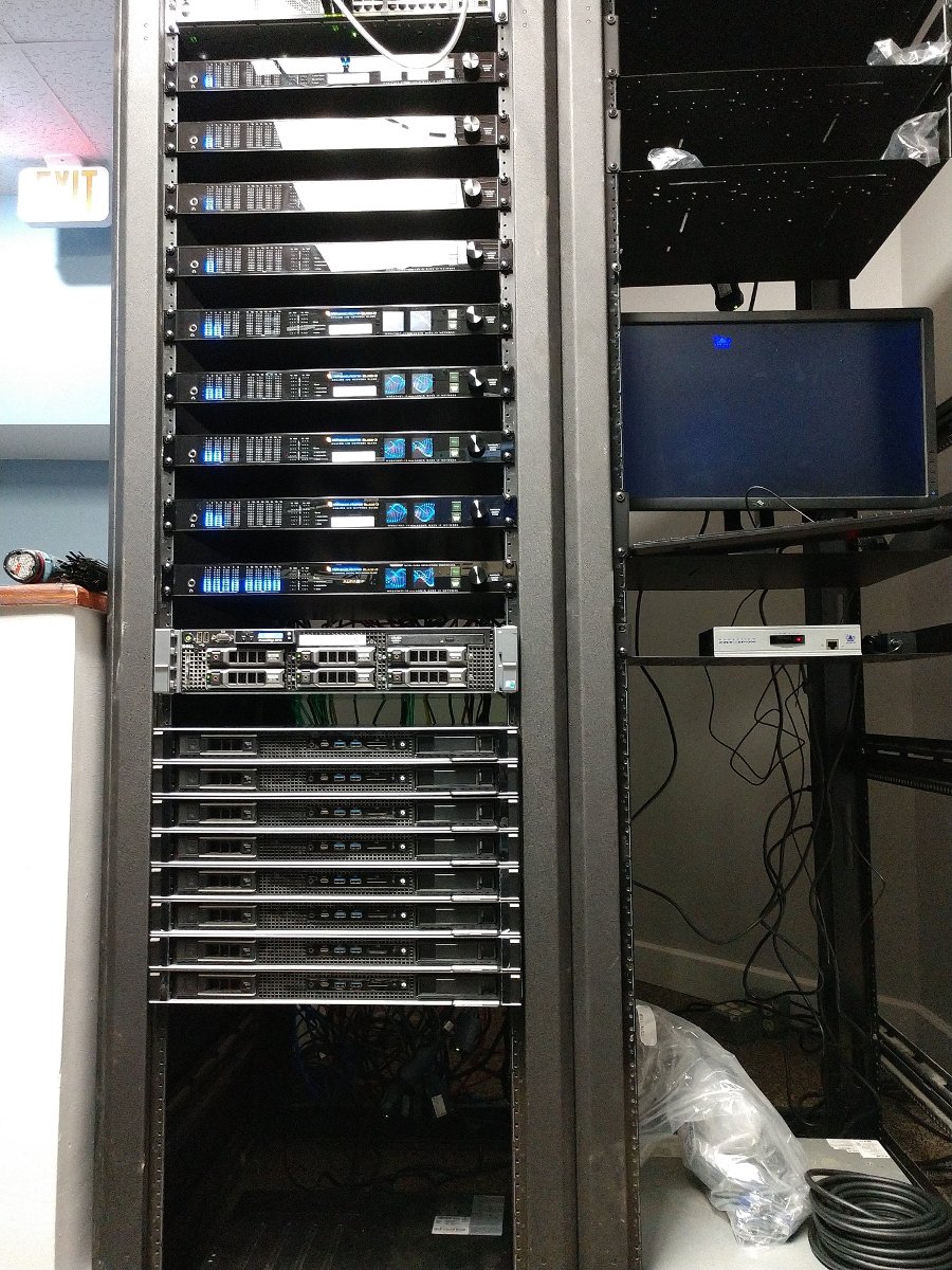
Nowadays, what used to be a studio location is more akin to a content distribution node.  This rack combines music and commercials stored locally on hard drives with out-of-town voice tracks and serves as the program source for eleven radio stations.

Radio Automation, 2020 style

It works remarkably well, as long as the windows operating system stays functional.