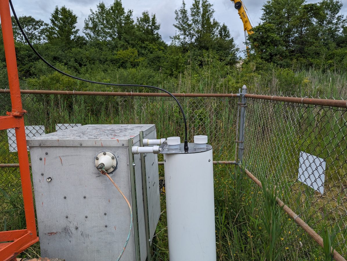
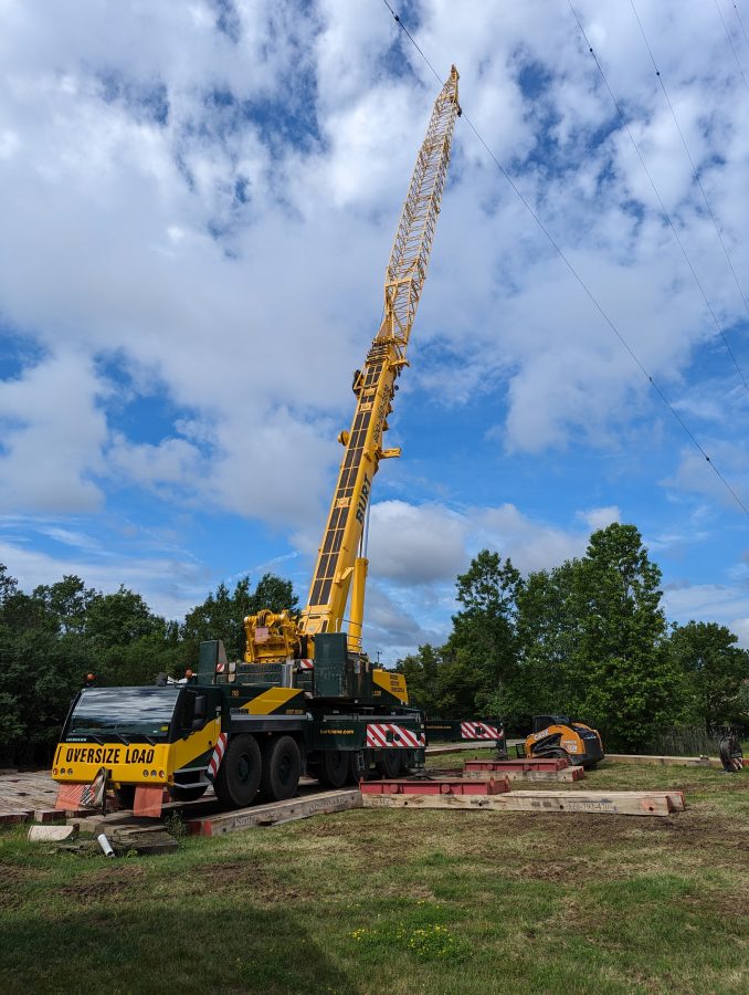
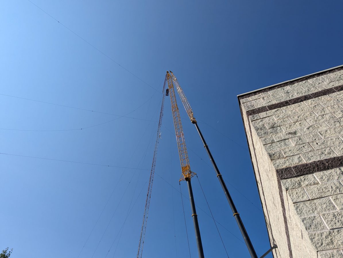
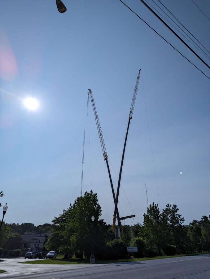
More AM work, Part V

I don’t know how many parts there should be in this series, five is a guess.

While some AM stations surrender their licenses to the FCC, others are undergoing needed repair work to stay on the air for a while longer.

WBEC-AM, Pittsfield, MA

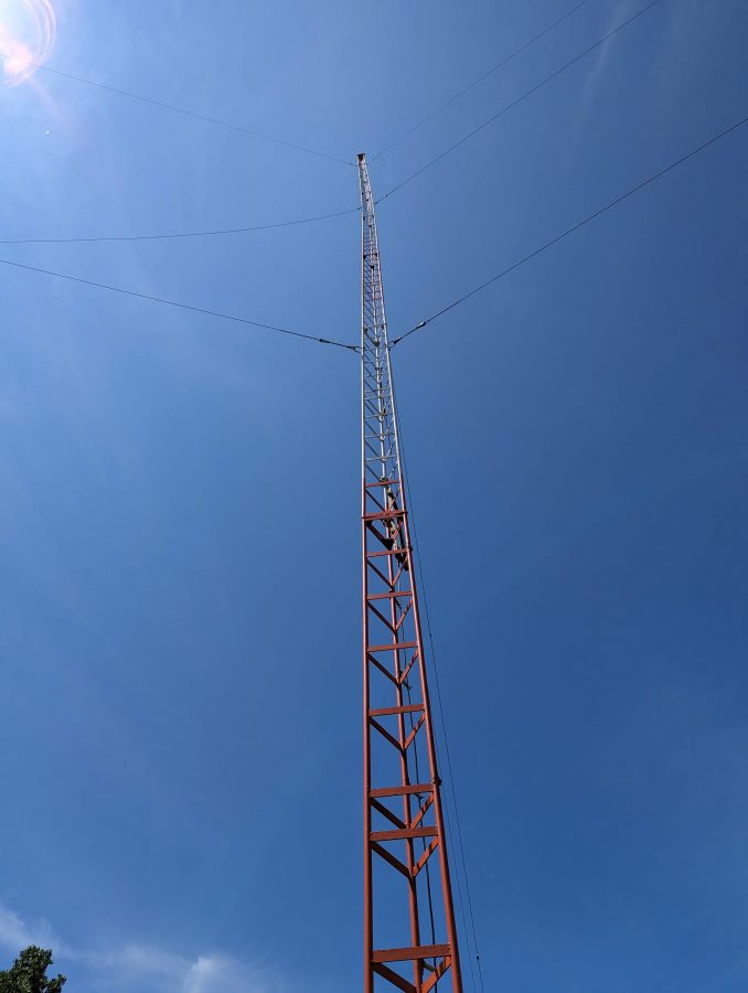
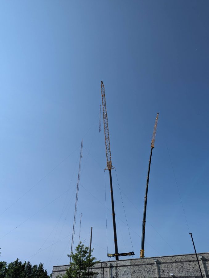
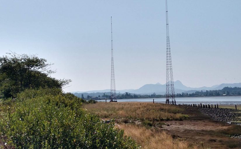
WBEC-AM in Pittsfield Mass is the topic of today’s post. This station is Non-Directional day, Directional Night with a two-tower array. This site was built around 1956 when the station moved from Eagle Street, near downtown Pittsfield.

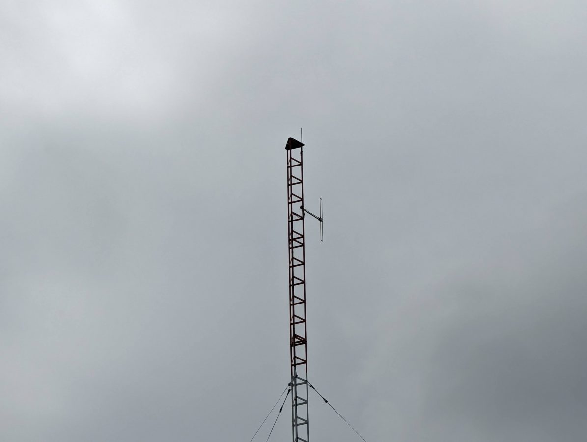
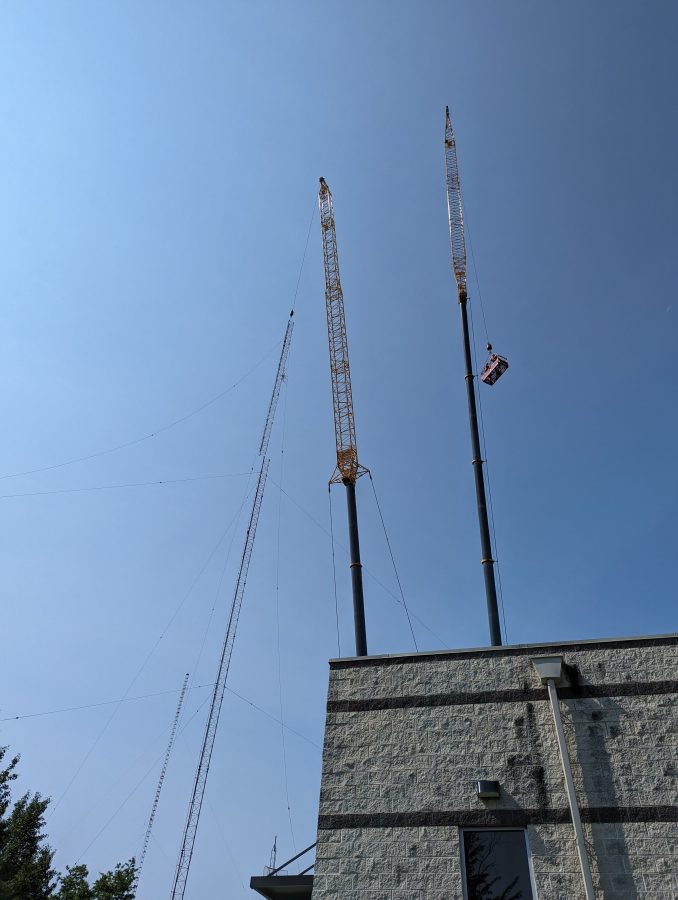
WBEC-FM backup antenna, mounted on WBEC-AM array

This Shively 4-bay antenna is the backup antenna for WBEC-FM. It is being replaced with a 3-bay antenna. The new antenna will serve W277CJ which is relocating from downtown and as a backup for WBEC-FM. A set of signal strength measurements for the nighttime directional array is required along each of the three monitor point radials before and after that work is completed.

The issue these days is the nighttime directional system, which is somewhat erratic when in use. The towers are 180 degrees tall with 35 degrees of top loading making the towers 215 degrees tall or just under 5/8 wavelength. As such both current and voltage are near maximum at the tower base, which makes them very sensitive to any changes at the base.

First, there was an issue with the tower lighting system. It seems that somewhere on the non-reference tower, the beacon conductor is shorted to the tower. When the tower lights are on, the loop current rises and falls in time with the beacon light. Because these are series excited towers, the fuse for the beacon does not blow, but the 60-cycle AC current does show up on the tower loop current reading. Rather than try to repair things on an almost 70-year-old tower light system, it was decided that both towers should get new LED lighting systems.

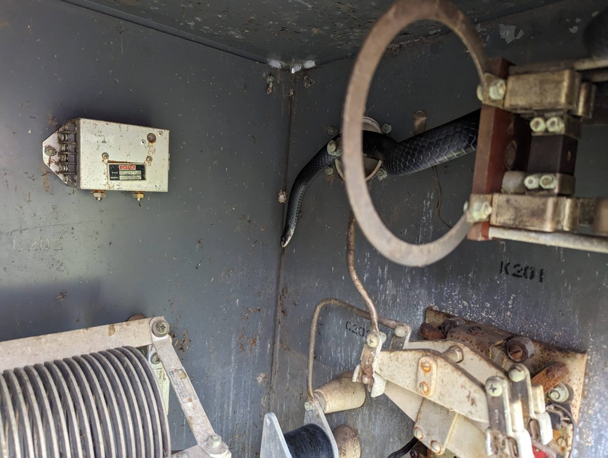
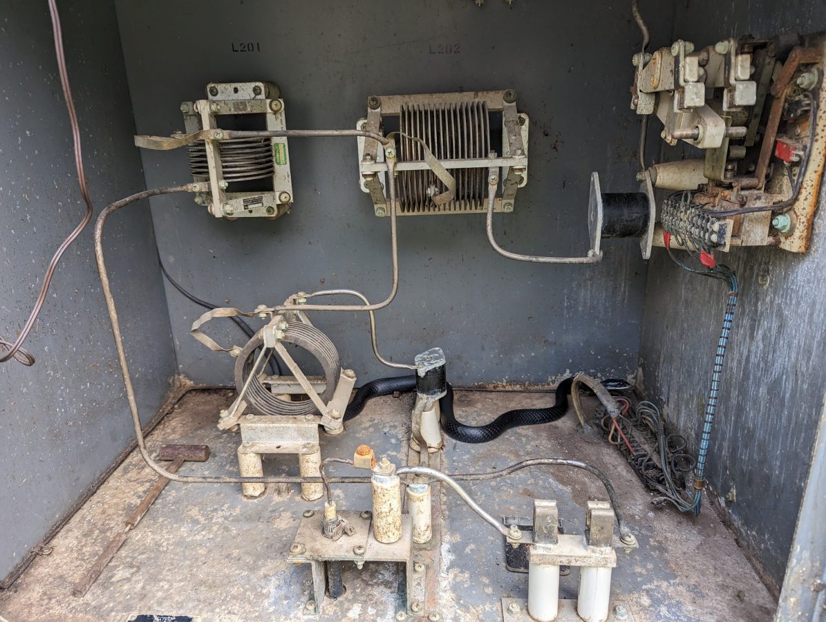
Next, mice chewed through several AC supply cables for the phasor at the base of tower #1. When switching from day to night patterns, some or all of the contactors would not move or get hung up between states taking the station off the air.

It is unfortunate that the phasor is at the base of one of the towers and the antenna monitor is back inside the building with the transmitter. It takes two people to make adjustments to the nighttime array.

The tower #1 ATU/phasor building is full of old unused equipment, a mouse haven. It also blocks access to several points that need to be sealed up to keep mice from getting in in the first place.

Slatercom LED light system controller

What is interesting is, that the original wiring and photocell failed at some point, and someone simply wired up a new photocell, leaving all of the old equipment in place. Thus, it became difficult to troubleshoot and ID the conductors in use vs the ones abandoned. With the replacement of the tower light systems, I decided that everything must go. The new Slatercom A-1 replacement lighting systems have individual controllers each with its own photocell. In addition, they have wireless links for tower light monitoring. It is great to get rid of the dry pairs going back to the transmitter room, which always creates RF and lightning headaches.

The station will also be saving some money on electricity. The new lighting system draws 88 watts total vs the old incandescent system which drew 1,000 watts with a 50% duty cycle on the beacons. The old system was on all the time due to photocell failure. I estimate they used 17,520 KWh per year on tower lights, at $0.20 per KWh which is $3,504.00 per year vs $308.00 per year for the LED systems. The added benefit of LED fixtures is that they should last much, much longer than incandescent fixtures.

WBEC-FM Harris FM1H3 transmitter scrapped

This lovely Harris FM1H3 was donated to the scrap yard. I believe that this is the second transmitter (1974) for the original 105.3 WBEC-FM which signed on in 1967.

Tower #1 ATU building cleaned out

The building clean-out, unwiring, and rewiring process took about a day and was well spent, in my opinion. Working in a building that is not full of mouse nests, droppings, and stinks like mouse urine is nice. I plugged several holes in the building with stainless steel pot scrubbers and spray foam.

Nautel Amphet 1 transmitter

After removing and replacing the old tower lighting system, the Nautel Amphet 1 transmitter would not run into the nighttime array. This was likely due to the changes at the tower base. I used a VNA to measure each tower’s base impedance which is 42.5 ohms and -j139, 44.5 ohms -j155 respectively.

WBEC Tower #1 base impedance
WBEC Tower #2 Base Impedance

Then the daytime and nighttime common point impedance was measured. Both were off, but the nighttime was more so than the daytime. I adjusted the R and X until both were reasonable and the transmitter would run into both patterns. According to Nautel, the Amphet 1 transmitter runs best into a load of 50 ohms j+5 measured at the transmitter output.

WBEC antenna system schematic

The daytime antenna is non-directional and there is no “common point,” however, there is an R and X adjustment in the phasor for the daytime tower. According to the file I found, it used to be a directional daytime until 1967, when they could make the daytime antenna non-directional. It is an interesting setup.

With the array properly adjusted, readings could be made along the monitor point radials. This station has three monitor points, two are in the nulls and one is in the main lobe. It is the nulls that are the greatest concern. Fortunately, much of the documentation from the original proofs was found in a filing cabinet. While the maps are nice, they date from 1950 and are woefully out of date. However, I was able to find good reference points on the 1950 maps and redraw radials on a Google map.

I found these photos of the monitor points as they were in 1956:

1956 photographs of an engineer making field strength measurements

Those were great because I was able to verify the locations of the monitor points today:

243-degree radial monitor point, 2024

Based on that, I made three maps with radials on the monitor point azimuths:

WBEC-AM Pittsfield, MA 243-degree radial ten measurements

The consulting engineer wanted about 10 readings on each radial. I created an individual map for each radial, marking points where the radial crosses a public road. When it came time to do the monitor points, I loaded the map into my smartphone and followed the directions to each point. It worked very well.

We will return and make post-installation measurements once the new FM antenna is installed.

AM Shut-downs

The big question; how bad is it?

The short answer; Not terrible, not great.

Short summary in a chart:

ServiceLicenses CanceledLicensed and SilentComment
Full Power AM812105Since 1991*
Full Power FM51788Since 1991
Low Power FM50251Since 2005
FM translator1677138
FM Booster16511Since 1991
Summary of silent and canceled licenses

*1991 was the peak number of AM licenses. It also marks when the FCC record-keeping began tracking the license status of all services.

There are 10,846 full-power FM stations, 8,374 FM Translators, 1,910 Low-Power FM stations, and 373 FM boosters currently licensed as of this writing.

According to the FCC data, the peak number of AM stations occurred at the end of 1991 with a total of 4,985. As of August 2024, there are 4,303 stations. There are 105 AM stations licensed and silent.

AM station licenses are being surrendered to the FCC at an increasing rate in the post-Covid era. I like charts. It is fun to look at raw data sorted in different ways. Fortunately, the FCC’s license management system allows one to search for various categories e.g. “Full Power AM” and “License Cancelled.”

Here is a chart by year of the number of AM station licenses surrendered to the FCC:

YearLicenses surrenderedStatesComment
19921AR
19932FL, MS
19941GA
19950

199641SC, VA, GA, KY, LA, FL, NC, TX, CA, OK, AR, MT, KS, AL, PA, TN, MS, IL, MN, FL, MI, UT, ME, IAFCC 96-218 rulemaking
199733SC, NY, CT, AR, GA, LA, NJ, AL, VA, FL, ME, AZ, MS, MD, CO, WV, MI, CA, NC, SC, TX, VTFCC 96-218 rulemaking
19989PA, NC, MO, CA, WV, TX, CT, AL
199911CA, PA, LA, IN, NM, VA, NY, MD, TX, WI
20006FL, CA, VA, WV, PADot-Com crash
200112IA, NC, SC, IA, AR, ND, CA, VA, RI, OK, OH
200214MI, GA, TX, PA, IA, MI, AR, AK, KY, MS, MP (Northern Mariana Islands)
200315CA, AK, MI, PA, MS, ME, CO, GA, KY, AL, CO, VA
200434NC, GA, CO, MS, SC, PR (Puerto Rico), LA, MI, OH, TX, FL, AR, CA, UT
200511TX, GA, CA, AR, IA, PA, MI, OR
200616TX, PA, AR, MI, OR, MS, IL, MN, OK, WA
20079GA, AR, TN, OR, VA, TX, MA, MO
20084FL, MI, PA, AL
20097MI, IL, OK, OR, LA, IDSub-prime mortgage crash
20107NY, VA, TX, PA, AL, WV
201132MS, AL, GA, VI (Virgin Islands), MD, MI, AS, TX, AR, IN, FL, TN, SC, NM, IA, NY, PA, LA, VT, NC
201225MS, FL, LA, TX, DE, KY, TN, IN, AL, GA, OH, PA, IL, MS, NC, MI, UT, SC. FL
201320MS, PA, OR, AL, MT, OK, TX, SC, NV, NM, NH, GA, TN
201422SC, CO, AK, AS (American Samoa), IL, AR, PA, RI, GA. IN, MA, MI, TX, NY, MS, WY, AL, MT, VA, LA, MO
201521AR, GA, WI, AL, NE, NV, HI, SC, NY, UT, MO, TN, KY, MA, IL, AR, AL, AK
201622DE, SC, HI, WI, MS, AL, OH, NV, MT, GA, NY, MO
201719NC, KY, CT, MO, GA, IL, TN, WY, NY, CA, OH, NH, PA
201818MD, KY, GA, NC, IL, GA, MS, UT, VA, LA, NY, MT, AR
201933AL, SC, OR, AR, TN, NC, WY, IN, KS, HI, WA, AL, IL, KY, HI, VI, VA, GA, LA, CA
202060MO, NE, FL, GA, LA, ID, TX, MP, AR, AK, KY, IL, AL, NJ, TN, MI, SD, MS, VA, CO, OH, SC, NM, WI, ND, AZ, OR, MD, PA, NVCovid-19 crash
202146MI, FL, AL, NV, GA, NM, PA, AZ, IN, OH, TX, IA, OR, CA, VA, IL, TX, TN, CA, NC, LA, OR, AZ, MS, SC, WV, WA, PA
202221FL, MS, AR, VA, MT, NY, KY, TN, SC, ME, NC, NM, MO, TX, GA, VT, PA
2023188TX, SC, MI, CA, ID, IL, OR, MD, MA, NM, AR, FL, KY, OH, TN, NC, LA, AR, CO, ME, MS, GA, WA, MI, OH, PA, VA, NJ, WI, NY, HI, NH, UT, IN, MT, SC, WV, IN, GU (Guam)The Great Cancellation of May 4, 2023
202435VA, AL, ME, LA, NC, MO, NY, SC, AZ, IL, NM, NV, WA, FL, TX, IN, WY, WA, KS, CA, MA, OH, NJ, AR, GA, CO, PA, VTAs of August 2024
US AM station cancelled licenses since 1992

A couple of things to note; there seems to be a two-year lag between any major economic downturn and a mass surrender of licenses. Covid-19 appears to be the exception. When the shutdowns came, clients canceled their advertising in mass causing a rapid end of already teetering businesses. In 1996, the FCC changed the rules on silent stations, limiting the time allowed to be silent to 12 months, after which the station license was canceled.

In 2023, the FCC performed a bit of housekeeping, canceling 188 AM expired station licenses some of which had been expired for decades. They performed the same thing for the FM band in October.

While every state and territory has at least one surrendered license, some states have more than average. Those tend to be mostly in the south; Alabama, Louisiana, Georgia, Florida, Mississippi, South Carolina, and Kentucky.

differed maintenance, AM transmitter site

Too many AM stations these days are dead men walking. It takes effort to keep an AM station on the air. Maintenance of antenna arrays, particularly directional systems, is expensive. Selling advertising is much more difficult than it is for FM stations. Local programming is expensive. The land under an AM tower is often worth more than the license itself.

4 Tower antenna system, WBNR, Beacon, NY

Land within certain city limits is a ripe target for developers. As more pressure mounts on station owners (taxes, zoning, etc) how long can they last before the inevitable happens?

Then there is the aging audience problem and in many smaller operations, the aging owners problem too.

The transition to digital modulation never happened. There are no AM stations running hybrid (MA1) HD radio. There are three AM stations that I know of that are running the all-digital (MA3) version of HD Radio.

In spite of those things, AM continues on.

Perhaps one reason; AM equipment is fairly simple in design and ease of use. Take away the electrical noise problem and it works well. AM radios are still ubiquitous in most houses, cars, hotel rooms, etc.

Many AM stations now have an FM translator, which is especially helpful if the AM station has to sign off at sunset or greatly reduce power. Some AM stations are simulcasting with full-power FM stations.

Crossed Field Antenna, Courtesy of Wikipedia

Are there any technological developments that would solve some of the issues facing AM broadcasters? More economical yet still efficient antenna designs that save space? A different modulation scheme that is still compatible with full-carrier AM and will work with older receivers (9K5R3E)?

Those question will likely remain unanswered. The FCC has shown no interest in allowing experimentation on the Medium Frequency band.

I Audited the RF Noise in my House

The largest problem facing analog AM broadcasting (and digital Medium Frequency and High Frequency broadcasting) is RF Noise.

Like most people, I have many modern conveniences that make my life easier than previous generations; electric lights, central heat and air conditioning, appliances like vacuum cleaners, microwave ovens, and whatnot. I enjoy the wireless internet, have an LED TV, use LED light bulbs, and get free electricity from my photovoltaic solar system. These devices can contribute to the high levels of RF noise found in most buildings. RF Noise which is the bain of AM broadcasting. Digital modulation schemes use variations in amplitude to transmit data bits. They are not immune to RF noise, they simply mask it better until they don’t.

I thought it would be interesting to isolate the various noise generators that may be present.

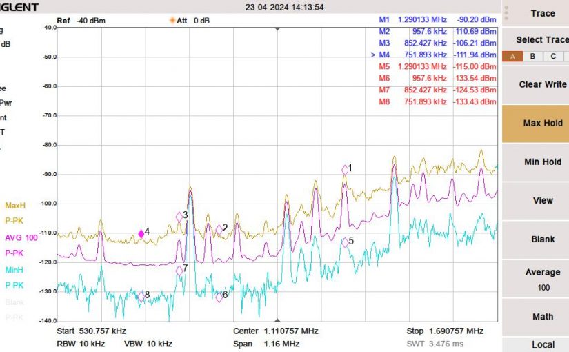
To make measurements, I used the Siglent SVA-1032X spectrum analyzer. This unit has a noise floor of -140 dB. My methodology is to turn everything off except the Device Under Test. Set the spectrum analyzer up for a wide band sweep, then narrow the bandwidth on any detected noise. Turn the DUT off to make sure that the noise goes away. Turn the DUT back on to make sure that the noise comes back.

The first thing I noticed; there is more noise during the daylight hours than at night. This is interesting. I thought it might be coming from my solar system, which uses individual inverters for each panel (so-called microinverters). These are wired to 240 VAC but have an internet gateway device that is in the house and communicates with the inverters using a power line data scheme. It turns out this was a minor contributor below the AM broadcast band.

By process of elimination, here are things that were not contributing to RF noise on Medium Frequency (AM band):

  • Cable Modem (Motorola MB7420 DOCSIS 3.0)
  • Router/WiFi gateway* (Netgear R6700v2)
  • GB Ethernet Switch (Netgear TLSG116E)
  • Dell Desktop PC’s (three models)
  • Dell Laptop PC (two models)
  • Android phones (two models)*
  • Phillips 4K LED large-screen TV (5PFL5604/F7)
  • LG LED computer monitor (24MK430H-B)
  • Refrigerator (Frigidaire FFTR1835VSD)
  • Stove (GE BP63D W1WH)
  • LG washing machine (WM3400CW)
  • LG clothes dryer (DLEX4501)
  • Bosch dishwasher (SGV68U53UC)
  • Dehumidifier (GE APEL70LTL1)
  • LED light bulbs (Sylvania 9W Ultra LED)
  • Generic incandescent light bulb
  • Furnace (fancy controller)
  • Furnace burner motor**

*These are intentional RF emitters

**The furnace burner motor made a small broadband RF signal on startup, likely the igniter which uses an electric arc. Once the unit was running, there was no further RF emissions noted.
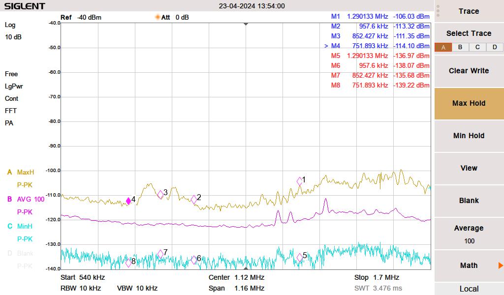
Medium Frequency baseline noise level

The yellow line is the peak hold, the magenta line is the 100 sweep average and the cyan line is the minimum peak hold. I live out in the sticks; there are no streetlights, no stoplights for miles, the nearest cellphone site is four miles away, and houses are spaced far apart.

First, I measured the noise with everything turned off. I then turned things on one by one, noting any changes in the spectrum. For the list noted above, this is the way it looked.

These are a few things contributing to RF noise levels on the MF band.

We have cheap Chinese grow lights to start seedlings for our vegetable garden. We were using these during the daytime hours to augment the low sunlight in early spring. I initially thought this was coming from the solar system. The interference was making a massive noise hump between 750 and 957 KHz. The brand of growlight is BestVA B-1000 LED which was purchased from Amazon.
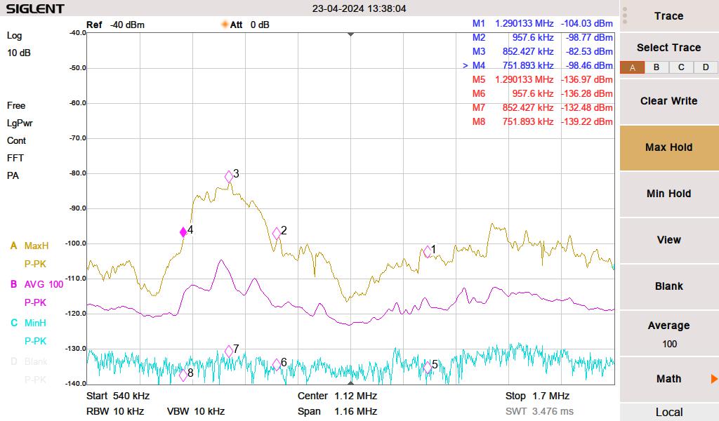
RF noise from Grow Light

Next, somewhat surprisingly, the LG computer monitor on my desk was creating a pretty decent rise from 1120 KHz to 1700 KHz. I have three LG computer monitors, this is the newest only this one creates any RF noise.
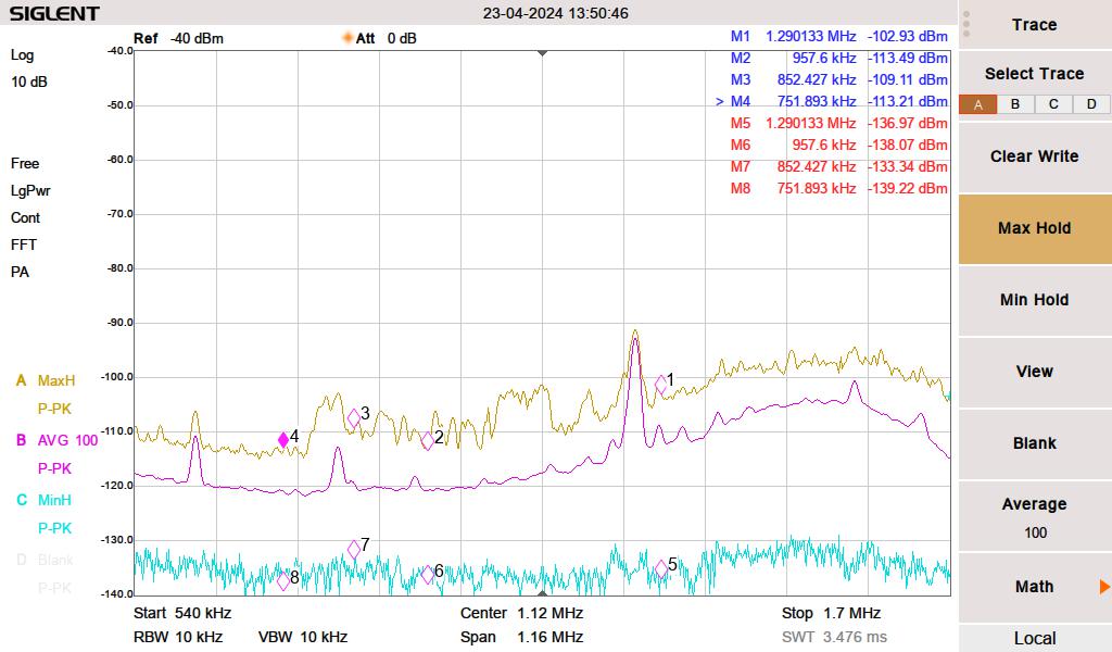
LG 240P500 LED monitor

Then, pretty much every florescent lamp (compact or full-length tube) created a broadband noise increase across the entire MF band and well into HF.
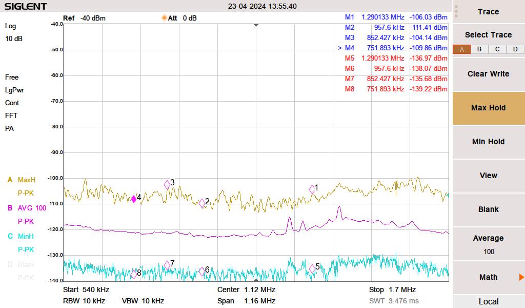
Florescent lighting

The vacuum cleaner makes a little bit of broadband RF noise when near the receiver. However, you cannot hear the radio when the vacuum is running, so that does not seem to matter.

None of these are surprising. However, I was more surprised that many other electronic devices are not contributing to RF noise in my house.

A little bit about data over power line or power line communications. Searching for power line data can be a bit tricky. First, there is this large voltage 60 Hz (plus harmonics) waveform to deal with. Secondly, there are many different protocols and many different frequencies. I narrowed down my solar system by listening to my Kenwood R-2000 below 300 KHz. Some noise went away when I completely disconnected the inverters. I don’t know the exact frequency, the protocol, the modulation type, etc. But there is something.

Data Over Power line is popular with home automation systems, it can be used to extend Ethernet LAN, and some power companies are using it to control substation equipment, smart power meters, and/or to function as an ISP for their customers. I have heard some HF users complain about BBPL, but I have not experienced it for myself.

The Nautel J-1000

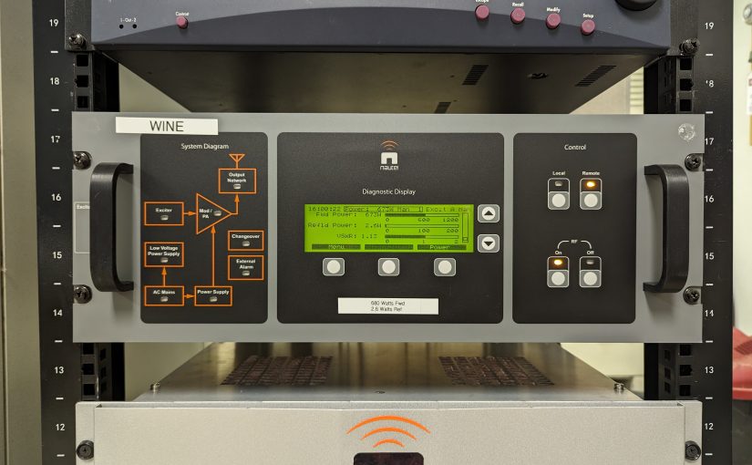
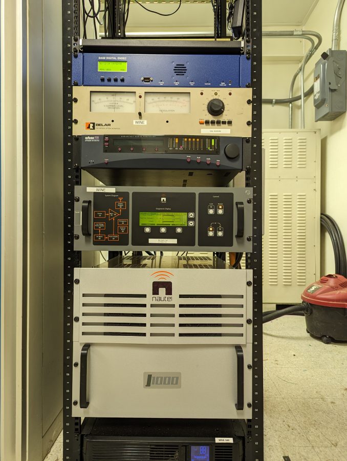
I Finished up this installation of a J-1000 in Brookfield, Connecticut for Nossa Radio. That is a Portuguese broadcaster that owns three other stations in the US.

WINE 940 KHz Brookfield, CT

These Nautels are fairly simple affairs; a controller and two RF amps with incumbent power supplies.

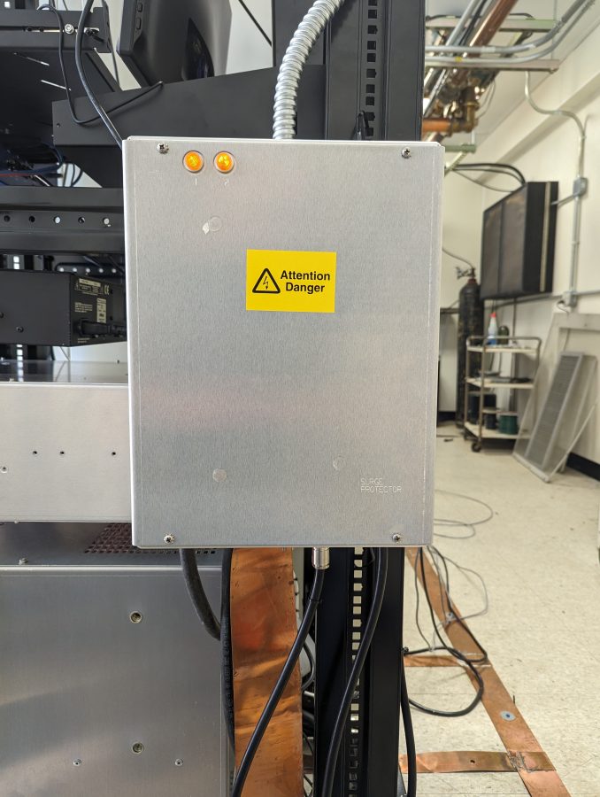
Nautel AM-RF and AC mains surge suppressor

Be sure to install the surge suppressor that comes with the transmitter.

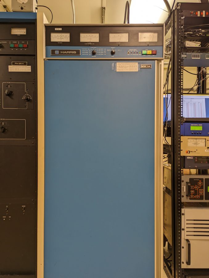
The J-1000 is replacing the 43-year-old Harris MW-1A which will function as a backup. Like all new transmitter installations; some things must be done to complete the job.

Harris MW1A

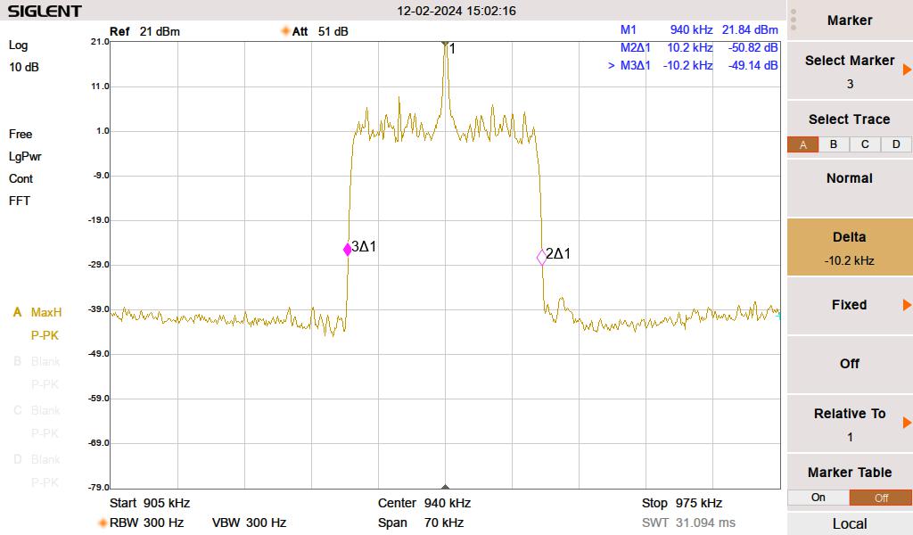
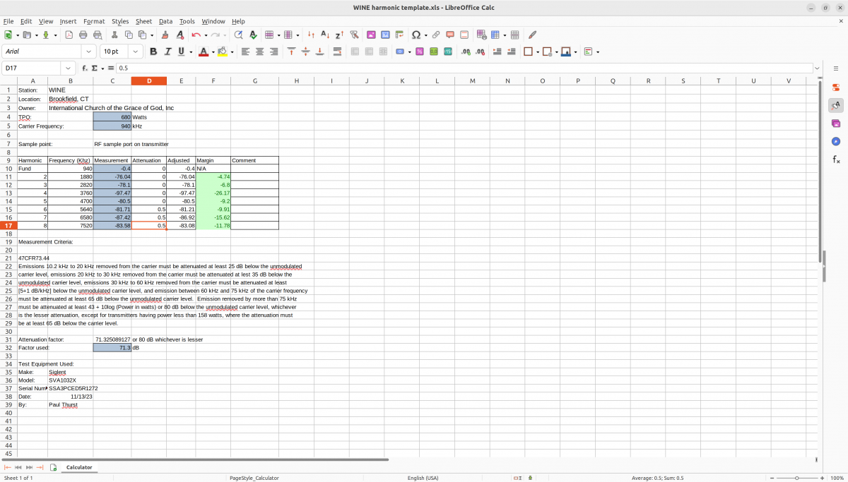
Harmonic measurements out to about the 5th or 6th harmonic need to be documented and compliant with NRSC-2 (AM mask requirements). Although NRSC-2 measurements are required, I don’t see how they can enforce that specification after AM HD radio came into being. Nevertheless, it was measured and passed. With the station carrier power of 680 watts, I used the RF monitor port on the back of the transmitter to make the measurement. Otherwise, I would need to find an empty field somewhere 1 KM away and stand in the middle of it to reduce all of the electrical noise.

Spectrum Mask from a Spectrum Analyzer

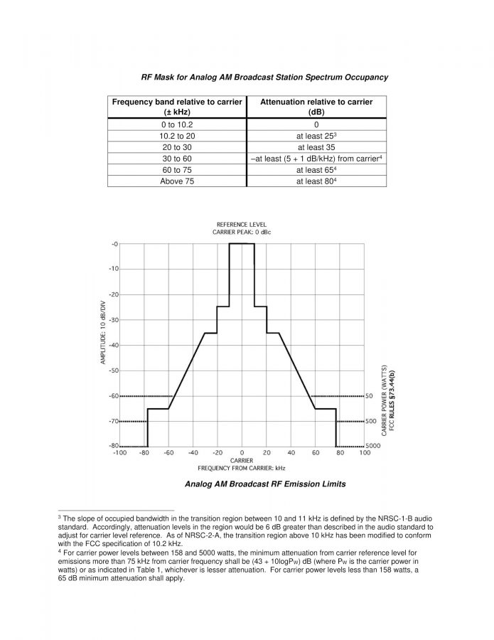
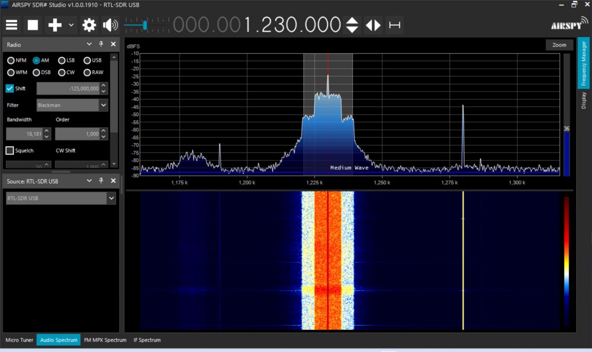
The NRSC-2 mask is mainly a function of High-Frequency limitation in the audio processor—certain transmitters, like the aforementioned MW1A did make some contributions to out-of-tolerance measurements.

NRSC-2C AM mask requirements
Harmonics measurements
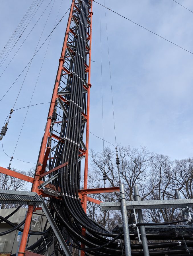
WINE folded unipole feed point

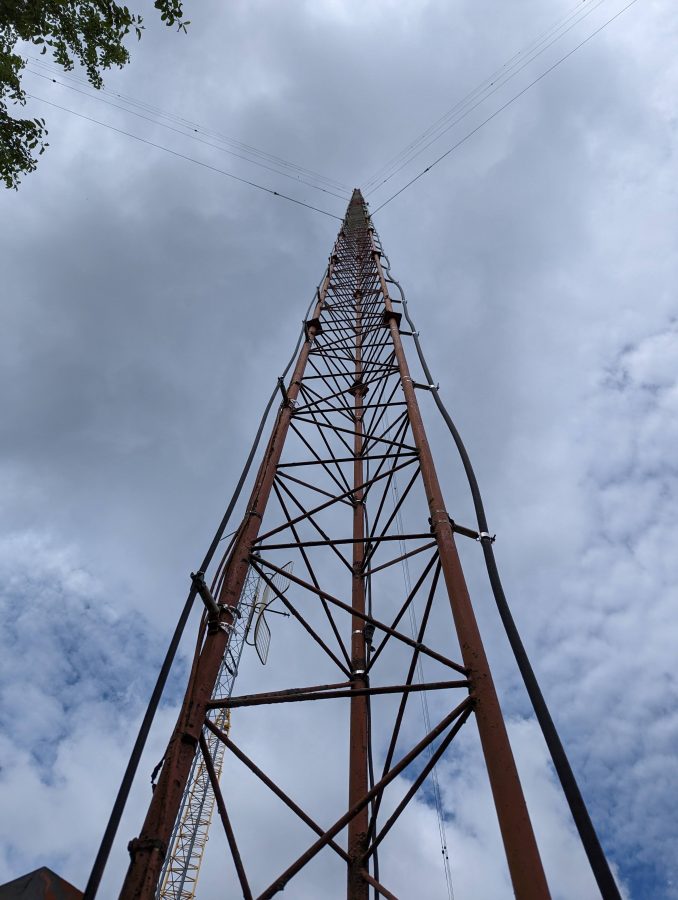
The antenna is a skirted tower that has many other services colocated on it. At the top is WRKI.

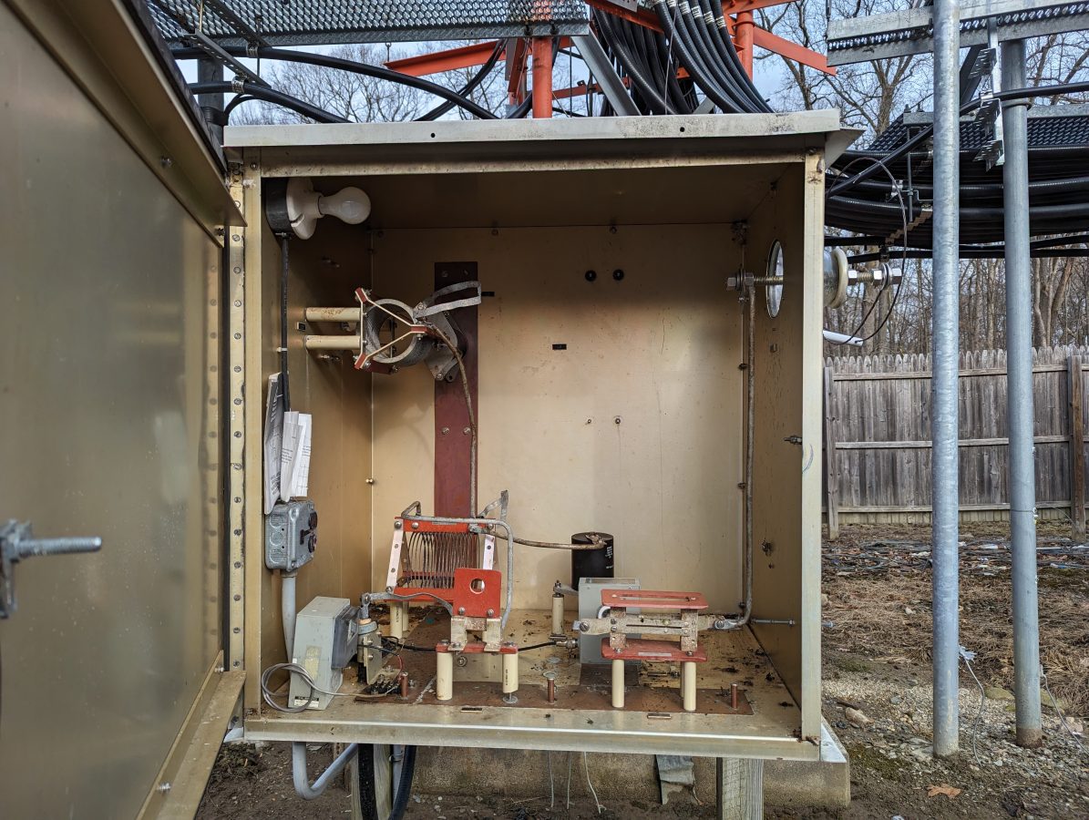
WINE ATU
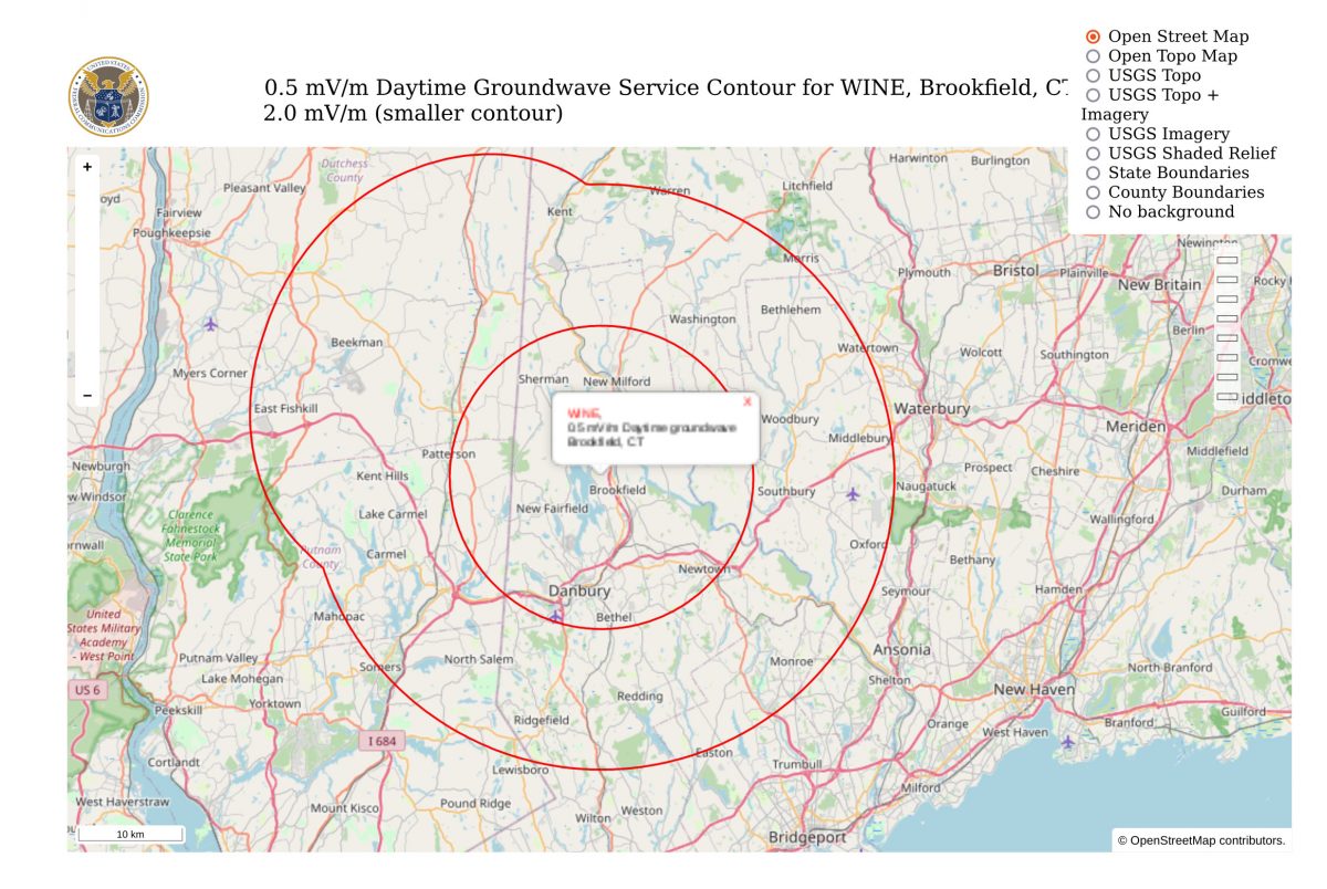
WINE daytime coverage map

Driving away from this site, I would have to agree with the predicted contour map above, at least on the highway. I think it may be a bit different driving around in town.