The public TV viewers in the St. Lawrence Valley get an updated transmission system. I recently finished installing this GatesAir ULXTE-6 transmitter in South Colton, NY. That is way up on the very northern fringes of the Adirondack Mountains. It replaces the Thales CCT-U-TDU2 8KW UHF TV transmitter, which was installed around 2004, early on during the analog/digital TV conversion.
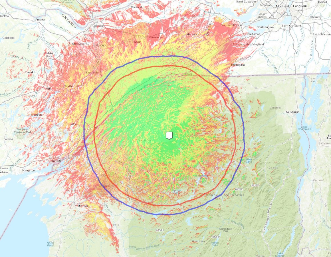
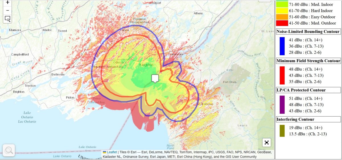
WNPI-DT coverage map
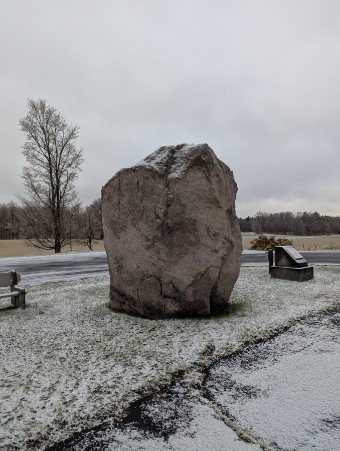
South Colton, NY is home of Sunday Rock. According the the historical marker:
This glacial bolder (erratic), twice preserved by local citizens, marks the gateway to the “Great South Woods.” In frontier days it was said that there was no law or Sunday beyond this point. May all who pass this way continue to enjoy the beauty of the mountains.
Sunday Rock, South Colton, NY
This in the northern end of the lake effect snow belt, where the average yearly snowfall tops 6 to 10 feet. Sometimes there is continuous snowfall starting in November and ending when Lake Ontario finally freezes in late January or February.
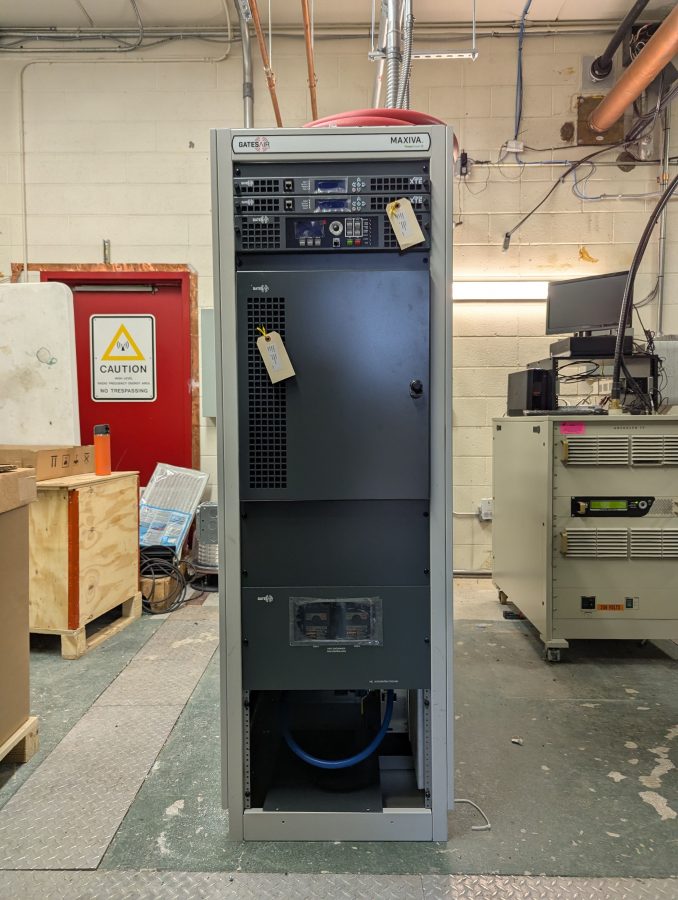
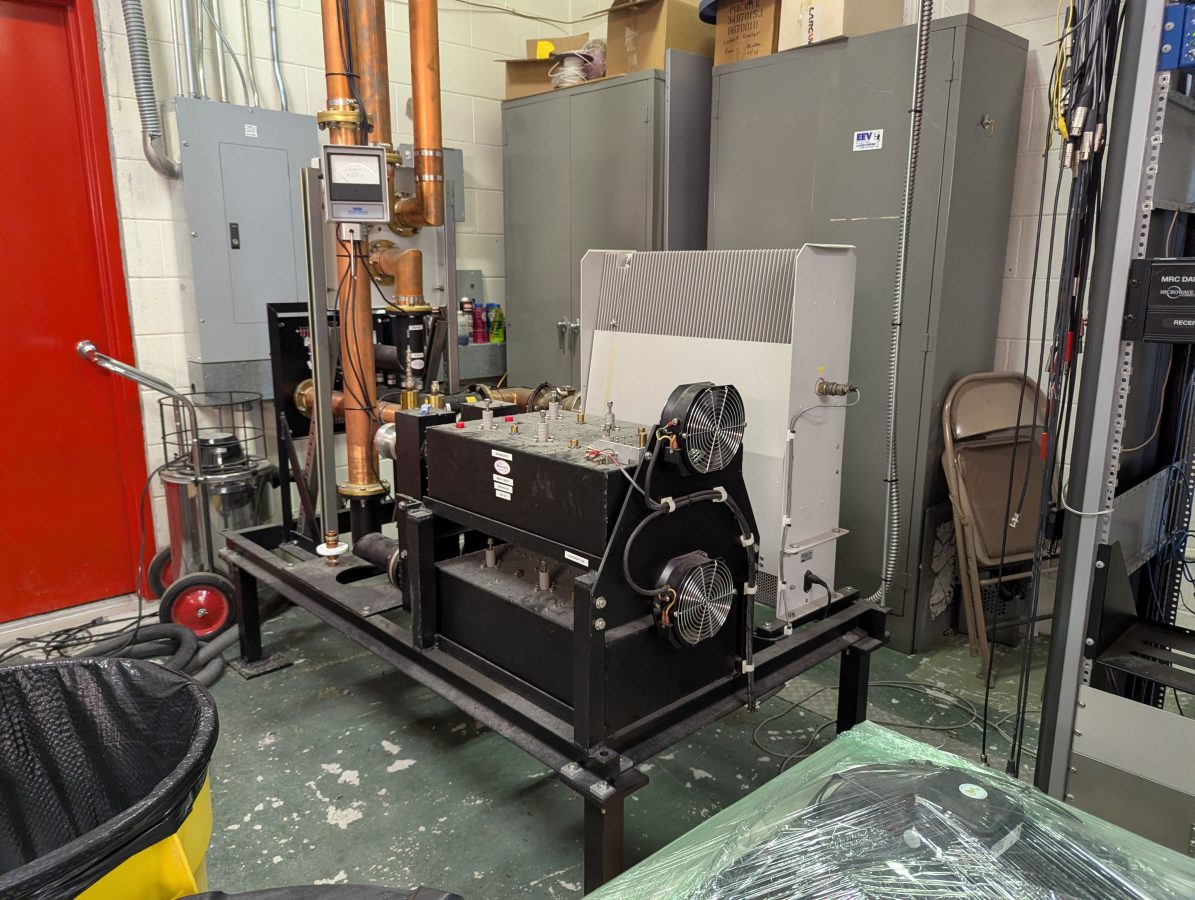
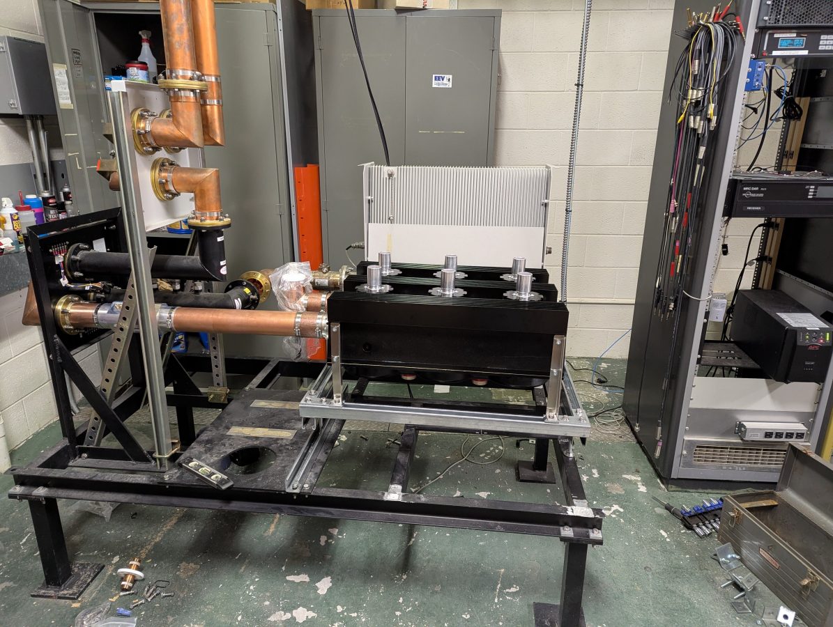
Back to the business at hand; the new transmitter placed:
ULXTE-6 transmitter
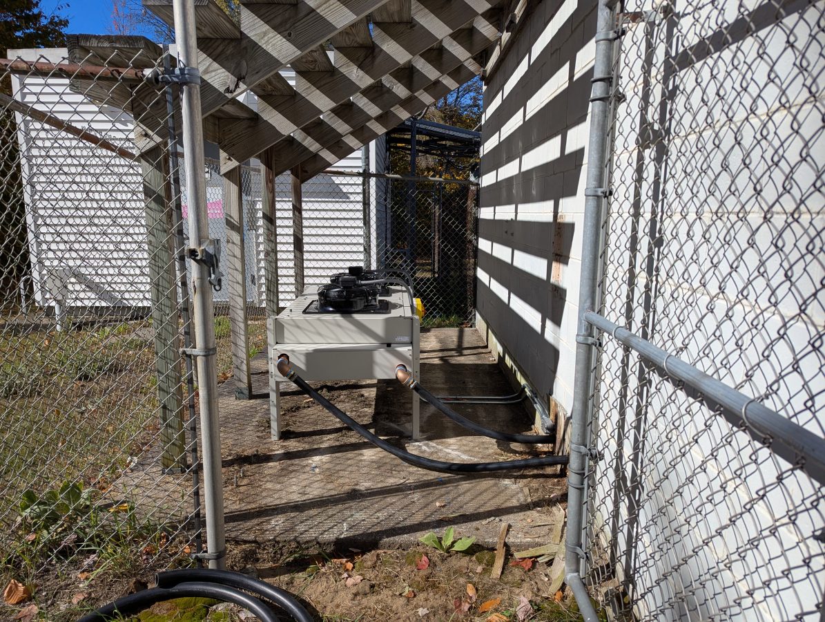
The 25 KW heat exchanger was placed where the old analog heat exchanger was:
25 KW heat exchanger
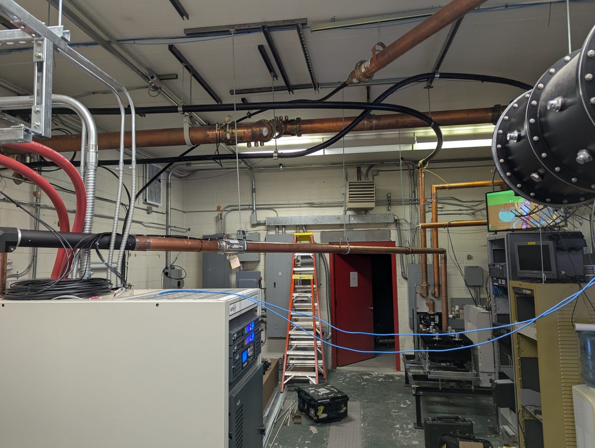
This system uses 1 1/4 inch flexible tubing, which is easier to work with than the 1 1/2 inch steel reenforced tubing.
ULXTE-6 HTF tubing run
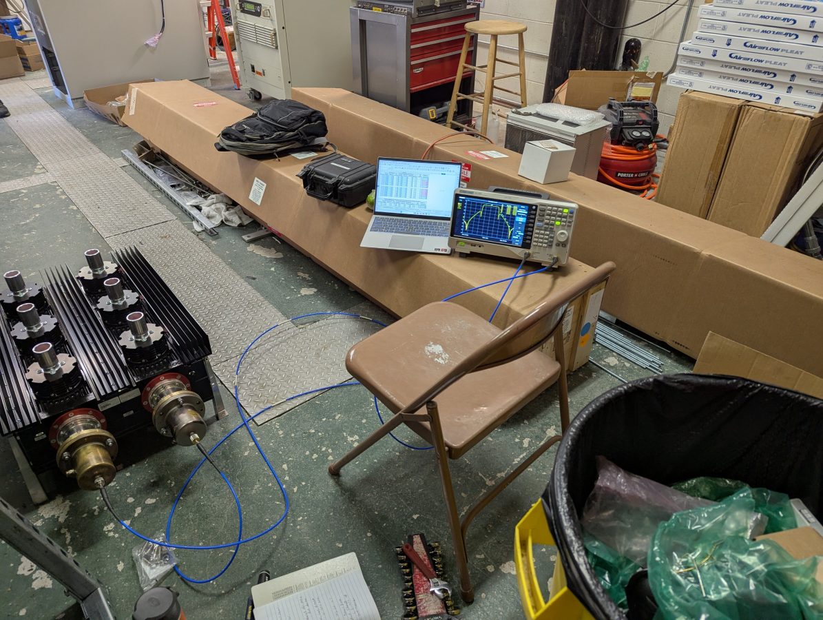
Measuring the Comtech mask filter with the network analyzer:
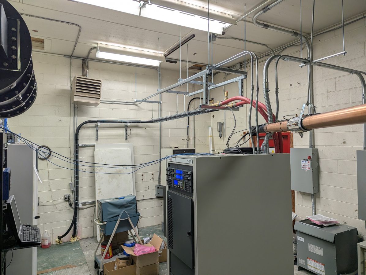
New mask filter mounted on the old dielectric mask filter stand:
New Comtech mask filter
This arrangement allows for the reuse of the two coax patch panels, on for antenna/dummy load, the other for main antenna/backup antenna.
3 inch rigid line between the transmitter and filter
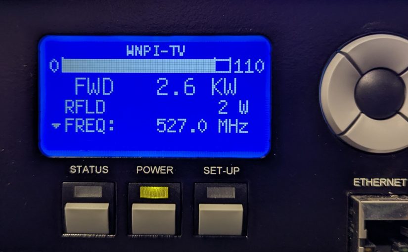
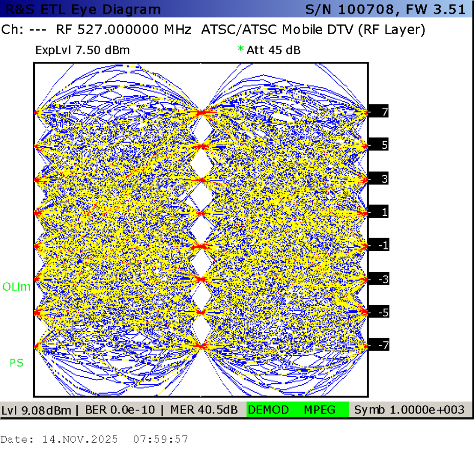
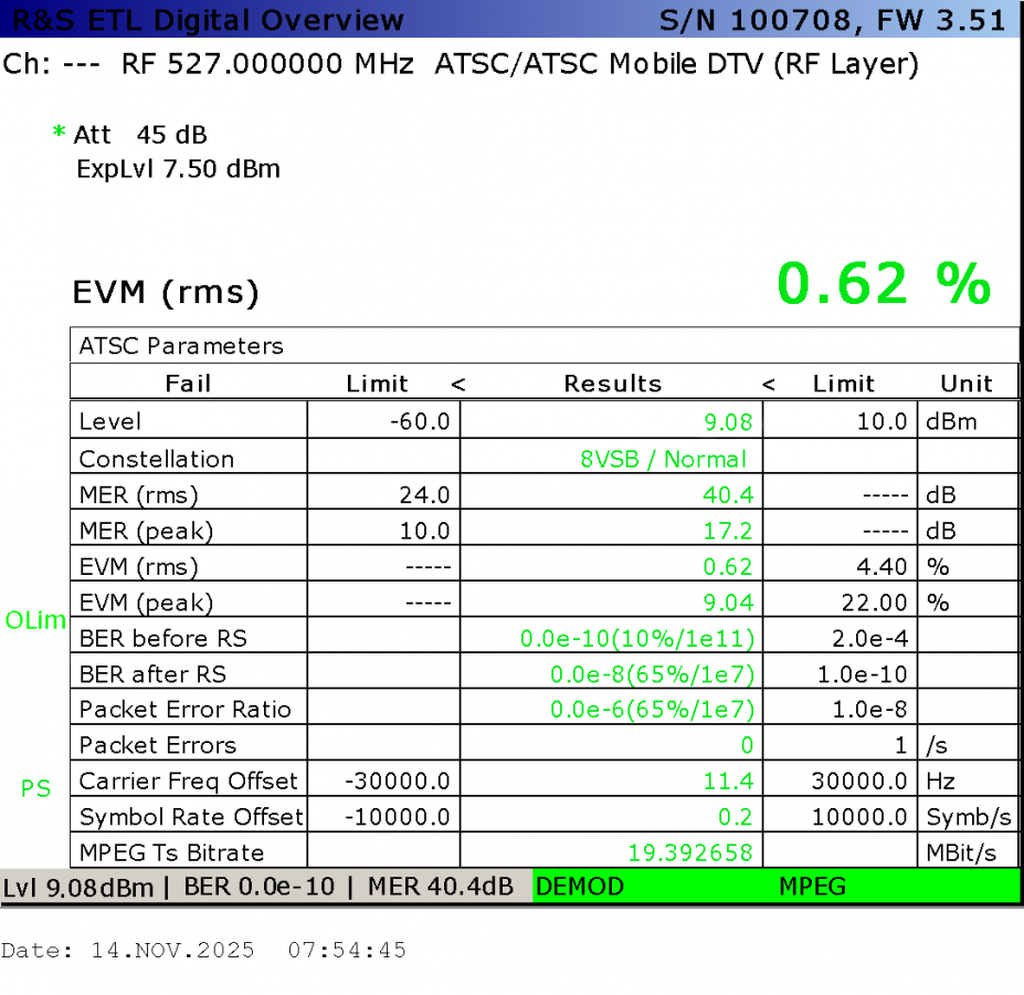
Post mask filter RF signal analysis using a Rohde Schwarz ETL:
The GatesAir equipment always has good performance parameters.
The carrier frequency is measured using the pilot. In this case, both exciters have the GPS reference connected and working. I think the ETL OCXO might be 11 Hz low.
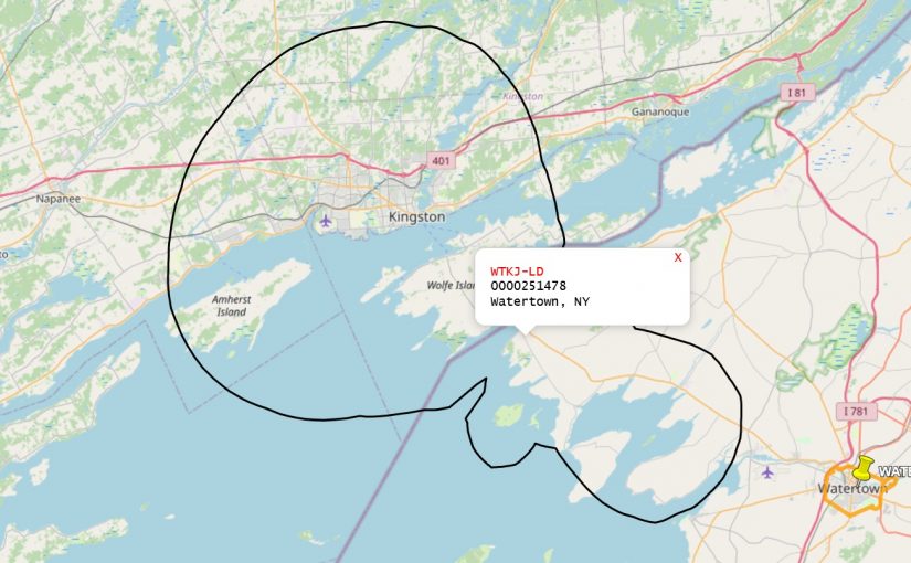
Installing another couple of these stations recently in the New York/Canadian border region. In this case, WTKJ-LD now transmitting from Cape Vincent, NY. This is owned by Sagamore Hill broadcasting and is retransmitting the NBC affiliate from Watertown, NY.
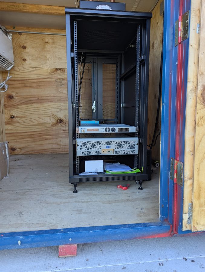
This is a pretty simple set up; BE 600 Watt UHF TV transmitter, Pro Television Exciter, 6 pole Dielectric Filter, and an 5 panel UHF antenna.
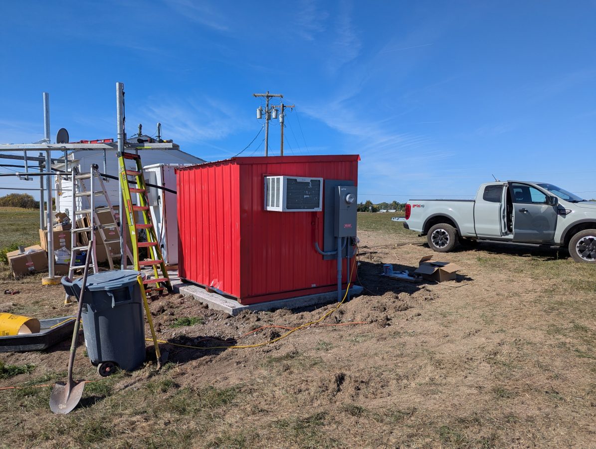
The shelter was made by Broadcast Electronics, it is somewhat small, but serviceable.
The LG window unit works well enough to keep the shelter cool. The transmitter runs at about 35% efficiency. The TPO is 470 watts, thus the transmitter puts out about 300 watts of heat into the room continuously.
The local cord cutters can get the following channels:
19.1
1080i
DD5.1
WVNC-NBC
19-2
480i (w)
DD2.0
Antenna TV
19-3
480i (w)
DD2.0
ION
19-4
480p (w)
DD2.0
Grit
19-5
480p (w)
DD2.0
Bounce TV
19-6
480p (w)
DD2.0
Court TV
19-7
480i (w)
DD2.0
QVC
19-8
480i (w)
DD2.0
SonLife
The weather up here is great! Cape Vincent is a nice small village with some decent local businesses. Unfortunately, summer is their main focus and many of them have closed down for the season. Still, there is a decent cup of coffee and the local market has a deli section that makes good sandwiches.
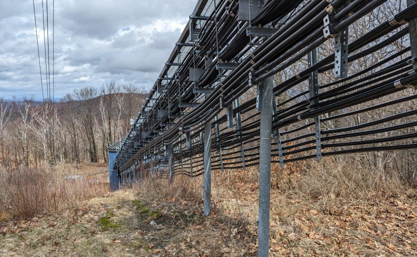
The ability to do a Distance to Fault Measurement can greatly speed up the troubleshooting of potential antenna and/or transmission line problems. DTF measurements take on one of two forms; Time Domain Reflectometry (TDR) and Frequency Domain Reflectrometry (FDR).
TDR is the traditional method of measuring Distance to Fault. The test equipment sends short DC pulses down the cable and measures any return loss or SWR. Energy reflected back toward the instrument will plotted based on the time difference between the transmitted signal and the received reflection, similar to RADAR. This works well finding opens or shorts, but may not see lesser faults that could still be causing problems.
Damaged six inch coax
FDR is now common in most field models of Vector Network Analyzers. An FDR sends a frequency sweep down the cable then uses an Inverse Fast Fourier Transform (FFT) function to convert the information into a time domain. FDR can more reliably detect smaller issues with cables such as kinks, sharp bends, water in the cable, poorly applied connectors, or bullet holes. The piece of dented cable above would not have given a large reflection on a TDR, but on an FDR it would show up very nicely.
Like a VNA, an FDR needs to be calibrated for the sweep frequencies in use. The frequency span or bandwidth of an FDR has a major role in DTF measurements. A wider span will result in more precise fault information, however, it will reduce the over all length that the instrument can test. For most broadcast RF applications, cable lengths are less than 670 meters (2200 feet). Many instruments will adjust the maximum distance automatically based on the chosen span and velocity factor.
For my equipment, a Siglent SVA 1032X, the maximum distance for any frequency span can be found with this formula:
Maximum Distance (meters) = 7.86 x 10⁴ x Velocity Factor/Span (MHz)
Thus, to get best resolution sweeping a cable that is 670 meters long with a velocity factor of 86%: 7.68 x 10,000 x .86 / 95 MHz = 695 Meters maximum distance.
The resolution for any frequency span can be calculated with the following formula:
In this case, the resolution would be +/- 1.35 meters. For shorter cable lengths a larger span can be used for better resolution.
My preference is to center the sweep frequency around the channel or frequency of the system under test.
To use a DTF function, a few inputs are needed:
The velocity factor of the transmission line
Cable attenuation for the swept frequency in dB/Meter
The approximate length of the line under test
The cable velocity factor and attenuation can be obtained from the manufacturer’s data sheet. Keep in mind that the manufacturer’s data is an estimation. These are usually pretty close to the actual number, but may vary due to tight bends in the cable, any splices, transitions to different cable, etc.
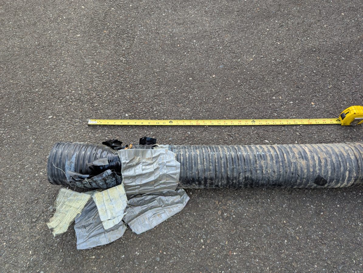
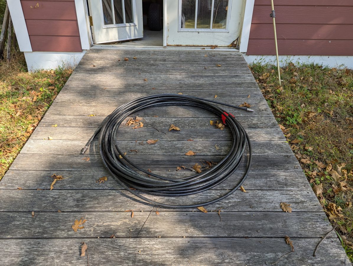
Cable to test
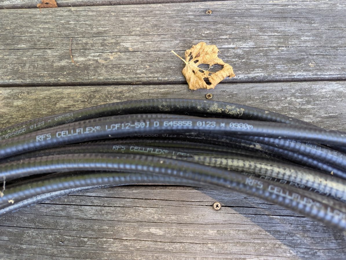
I had this used 1/2 inch RFS LCF12 50J cable in the barn, left over from project. Fortunately this is newer cable and it had the length marked out in meters. The beginning number was 0980 meters, the end was 1021 meters. Each meter marking has an asterisk before the number. I used a meter stick to measure out the distance between the asterisks and they are exactly one meter apart. I then measured the distance between the asterisk and the connector on each and ended up with 1.49 meters (4.9 feet) additional length, making the total length 42.49 meters (139.4 feet). The manufacture’s specification on velocity factor is 0.87 or 87% of the speed of light.
Manufacture’s markings
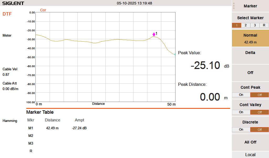
When I test this line with a 50 termination, it looks like this:
FDR DTF, 50 ohm termination at 42.49 meters
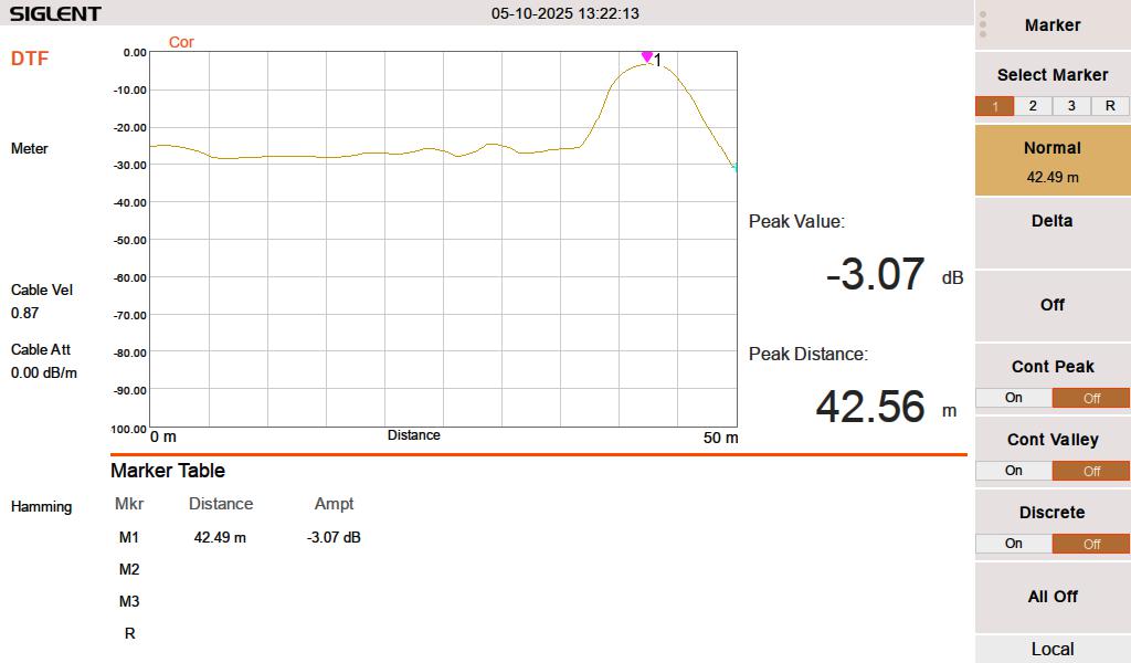
When I test the line either open or shorted, it looks like this:
FDR DTF, cable shorted at 42.49 meters
I swept the cable at HF frequencies (3-30 MHz) since I think that is what this is going to be used for. At 3 MHz, the cable has a loss of approximately 0.003 dB per meter, which is inconsequential for this test. The velocity factor of 0.87 is pretty close. A longer run might indicate that it is actually 0.875 or 0.88.
Velocity factor and cable impedance are very important when using the Moment of Methods (MOM) system for AM antenna work. In that situation, both need to be obtained with a VNA for the FCC application.
The best practice is to sweep into a terminated line. In an AM system, a termination can most often be applied at the ATU input J plug. Sweeping into an antenna is possible, however there are several things that may lead to poor results. Most often, an FM antenna will look like a short on a DTF measurement. A UHF slot antenna will look open. In addition to that, the DTF measurement may be corrupted by any signals being received by the antenna while the system is under test.
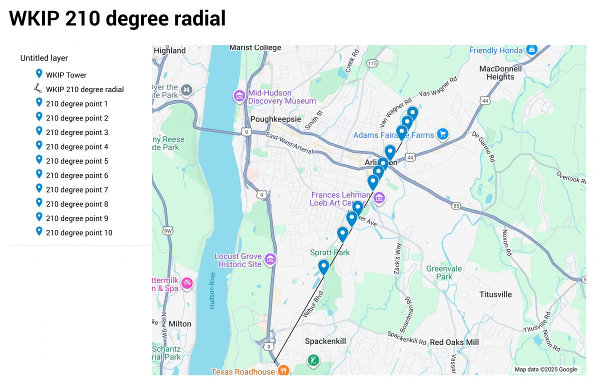
I have been finishing up a project which required detuning a new monopole installed near an AM tower. One requirement was a series of field strength measurements along six evenly spaced radials around the AM tower. The point is to see if there is any effect in the omni-directional AM signal (there should not be).
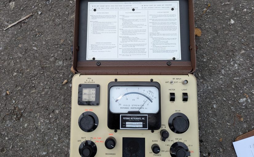
For this, I used the venerable Potomac Instruments FIM-41. As I recall, these units are rather pricey. The frequency range is 0.5 to 5.0 MHz. The basic measurement unit is a Volt/Meter, which is an electric field measurement. Something that measures 1 V/M means that the electric potential between two objects 1 meter apart is 1 volt. The meter will also make measurements in dBm, which is a logarithmic electromagnetic field strength measurement.
Before making any measurements, it is a good idea to check the batteries. Also, the hinged lid part is a loop antenna and there are several contact fingers which can get a little dirty which may effect the measurement accuracy. These should be cleaned off with some alcohol and a q-tip. I have also seen a pencil eraser used.
The directions for meter calibration are on the inside of the lid. Even though I have done this type of measurement a thousand times, I always do a quick read through the directions just to make sure I don’t skip any of the steps. Depending on the power of the signal being measured, I like to calibrate the meter at least a mile or so away from the AM antenna system.
Check the battery with the function switch in the Batt position. The meter should read within the Batt range
Tune the signal with the function switch in the FI-Cal-Tune position. This should be done at some distance away from the antenna system. Tune for maximum meter reading.
Rotate the FIM until the signal is below 10 mV/M, switch the full scale switch to CAL and adjust the CAL OSC for maximum meter reading.
Switch the Function switch to CAL NULL and adjust the GAIN control to minimum meter reading.
To take readings put the function switch in CAL TUNE and the Full Scale switch at whichever position results in an on scale reading. On less one of the knobs gets bumped, the meter only needs to be calibrated once.
Measurements should be made three or more hours after local sunrise and three or more hours before local sunset. This is to prevent other sky wave signals from interfering with the measurements. The first measurement should be greater than five times the tower height, in this case more than 240 meters.
I used Google Maps to generate a set of points along each radial then noted the coordinates and a brief description on a spread sheet. Since everything was on Google Maps, it was easy to navigate from one point to the next:
Field strength readings follow the inverse square law. Whatever the increase in the distance factor from the radiator, the electrical field will decrease inversely by the square of that factor. Thus, if the distance increases by 3, the field will decrease by a factor of 9.
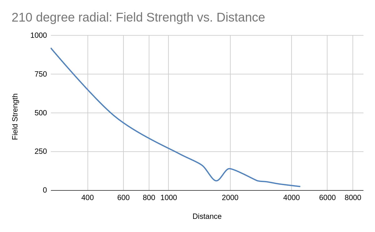
This can be seen in a field strength vs distance graph which I plotted on an Excel spreadsheet:
Field strength in mV/M, distance in Meters
You can see around 2 KM away, there is something re-radiating the signal. This was near a college campus with lots of vertical metal structures around. There are two readings which should probably be thrown out to smooth out the curve.
At one point, further out along this radial, my car was attacked by a Rottweiler. The dog owner just stood in his front yard and watched it happen. After he got the dog back under control, I rolled my window down and told him what I thought of his dog. It is for this reason, I have a dash camera in my work vehicles. Too many times things happen while driving.