I Audited the RF Noise in my House

The largest problem facing analog AM broadcasting (and digital Medium Frequency and High Frequency broadcasting) is RF Noise.

Like most people, I have many modern conveniences that make my life easier than previous generations; electric lights, central heat and air conditioning, appliances like vacuum cleaners, microwave ovens, and whatnot. I enjoy the wireless internet, have an LED TV, use LED light bulbs, and get free electricity from my photovoltaic solar system. These devices can contribute to the high levels of RF noise found in most buildings. RF Noise which is the bain of AM broadcasting. Digital modulation schemes use variations in amplitude to transmit data bits. They are not immune to RF noise, they simply mask it better until they don’t.

I thought it would be interesting to isolate the various noise generators that may be present.

To make measurements, I used the Siglent SVA-1032X spectrum analyzer. This unit has a noise floor of -140 dB. My methodology is to turn everything off except the Device Under Test. Set the spectrum analyzer up for a wide band sweep, then narrow the bandwidth on any detected noise. Turn the DUT off to make sure that the noise goes away. Turn the DUT back on to make sure that the noise comes back.

The first thing I noticed; there is more noise during the daylight hours than at night. This is interesting. I thought it might be coming from my solar system, which uses individual inverters for each panel (so-called microinverters). These are wired to 240 VAC but have an internet gateway device that is in the house and communicates with the inverters using a power line data scheme. It turns out this was a minor contributor below the AM broadcast band.

By process of elimination, here are things that were not contributing to RF noise on Medium Frequency (AM band):

  • Cable Modem (Motorola MB7420 DOCSIS 3.0)
  • Router/WiFi gateway* (Netgear R6700v2)
  • GB Ethernet Switch (Netgear TLSG116E)
  • Dell Desktop PC’s (three models)
  • Dell Laptop PC (two models)
  • Android phones (two models)*
  • Phillips 4K LED large-screen TV (5PFL5604/F7)
  • LG LED computer monitor (24MK430H-B)
  • Refrigerator (Frigidaire FFTR1835VSD)
  • Stove (GE BP63D W1WH)
  • LG washing machine (WM3400CW)
  • LG clothes dryer (DLEX4501)
  • Bosch dishwasher (SGV68U53UC)
  • Dehumidifier (GE APEL70LTL1)
  • LED light bulbs (Sylvania 9W Ultra LED)
  • Generic incandescent light bulb
  • Furnace (fancy controller)
  • Furnace burner motor**

*These are intentional RF emitters

**The furnace burner motor made a small broadband RF signal on startup, likely the igniter which uses an electric arc. Once the unit was running, there was no further RF emissions noted.
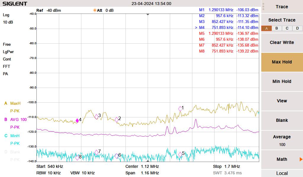
Medium Frequency baseline noise level

The yellow line is the peak hold, the magenta line is the 100 sweep average and the cyan line is the minimum peak hold. I live out in the sticks; there are no streetlights, no stoplights for miles, the nearest cellphone site is four miles away, and houses are spaced far apart.

First, I measured the noise with everything turned off. I then turned things on one by one, noting any changes in the spectrum. For the list noted above, this is the way it looked.

These are a few things contributing to RF noise levels on the MF band.

We have cheap Chinese grow lights to start seedlings for our vegetable garden. We were using these during the daytime hours to augment the low sunlight in early spring. I initially thought this was coming from the solar system. The interference was making a massive noise hump between 750 and 957 KHz. The brand of growlight is BestVA B-1000 LED which was purchased from Amazon.
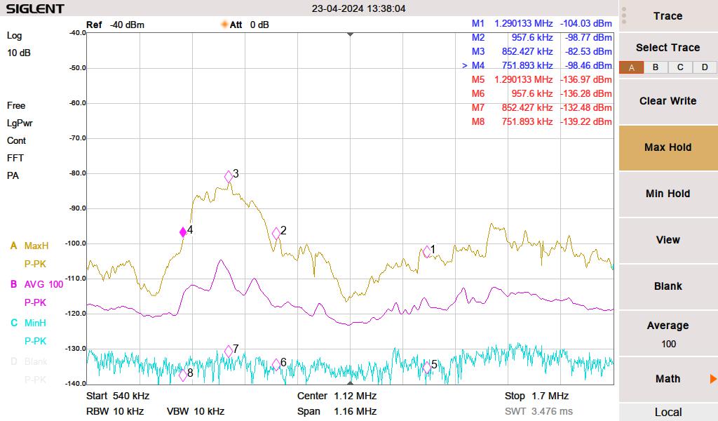
RF noise from Grow Light

Next, somewhat surprisingly, the LG computer monitor on my desk was creating a pretty decent rise from 1120 KHz to 1700 KHz. I have three LG computer monitors, this is the newest only this one creates any RF noise.
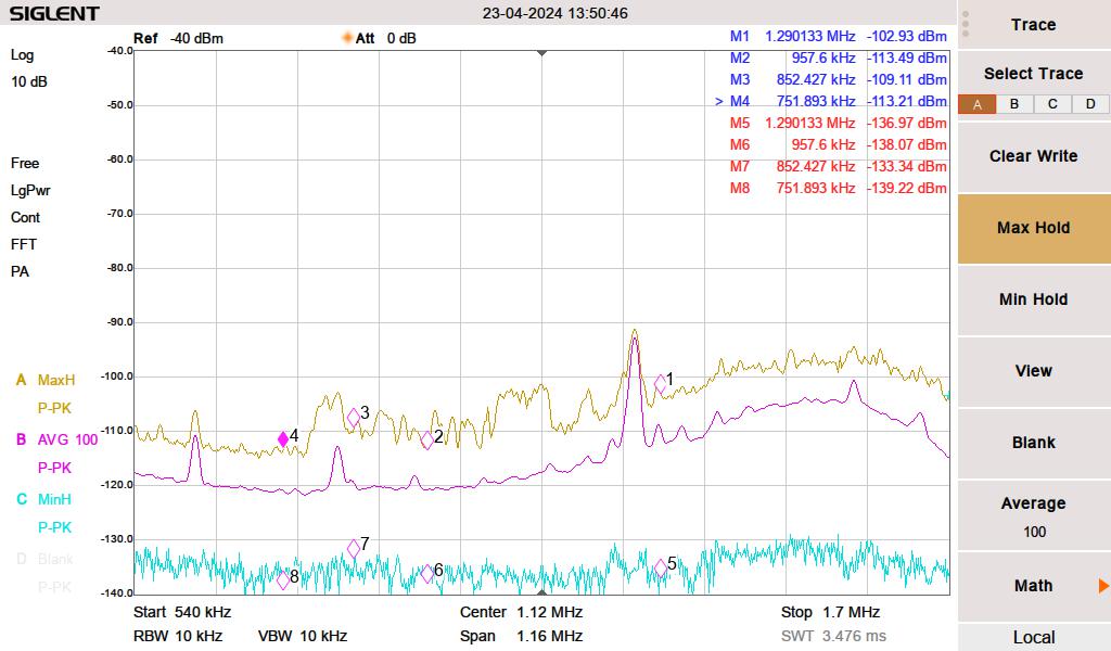
LG 240P500 LED monitor

Then, pretty much every florescent lamp (compact or full-length tube) created a broadband noise increase across the entire MF band and well into HF.
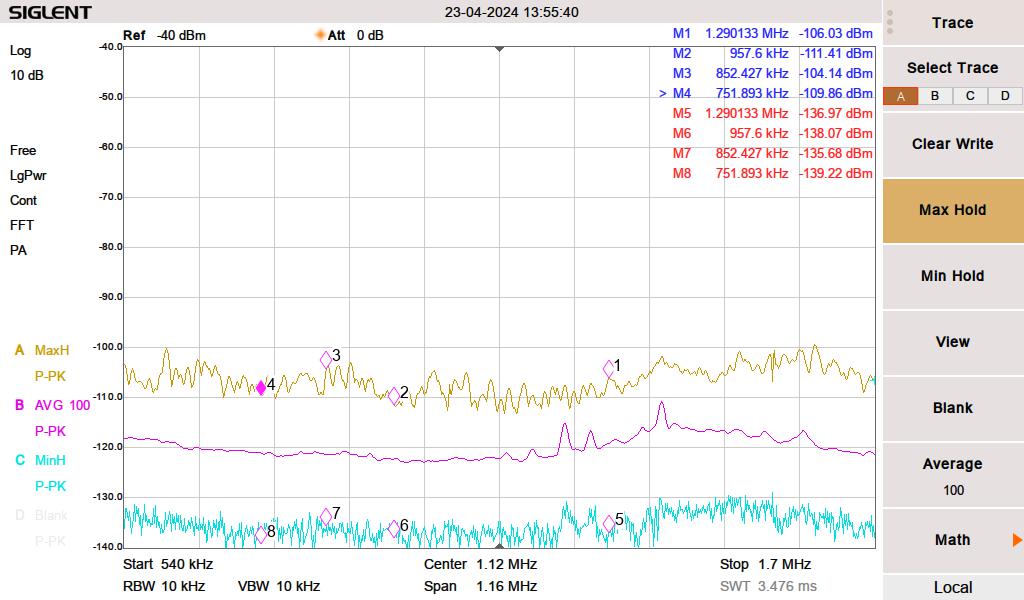
Florescent lighting

The vacuum cleaner makes a little bit of broadband RF noise when near the receiver. However, you cannot hear the radio when the vacuum is running, so that does not seem to matter.

None of these are surprising. However, I was more surprised that many other electronic devices are not contributing to RF noise in my house.

A little bit about data over power line or power line communications. Searching for power line data can be a bit tricky. First, there is this large voltage 60 Hz (plus harmonics) waveform to deal with. Secondly, there are many different protocols and many different frequencies. I narrowed down my solar system by listening to my Kenwood R-2000 below 300 KHz. Some noise went away when I completely disconnected the inverters. I don’t know the exact frequency, the protocol, the modulation type, etc. But there is something.

Data Over Power line is popular with home automation systems, it can be used to extend Ethernet LAN, and some power companies are using it to control substation equipment, smart power meters, and/or to function as an ISP for their customers. I have heard some HF users complain about BBPL, but I have not experienced it for myself.

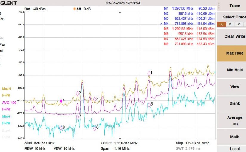
Making a notch filter

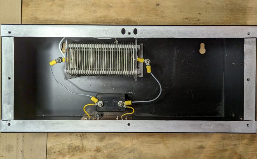
One small RF project that I am working on; a 770 KHz notch filter. I always figure if I am having this problem, then others may be having it too. This is a relatively simple idea, a resonant LC circuit (AKA a tank circuit) tuned to the carrier frequency. It should have a bandwidth of +/- 15 KHz of the design frequency. Another requirement; use the parts I have available. Finally, the environment in which this is to be used is a high-noise room; with lots of computers, LED lights, etc therefore it needs to have excellent RF shielding.

Something like this would work well for anyone that lives around an AM transmitter site and is having problems with receiver sensitivity or transmitter intermodulation.

The basic design looks like this:

Parallel LC tank circuit

Time for a trip to the local storage facility known as “The Barn.” In my backyard, there is a small agricultural structure that is used for storage of just about everything. In The Barn, I found several parts salvaged from an old Energy Onyx Pulsar AM transmitter. As such, they are more than capable of receiver operation and could likely handle a fair amount of RF power in the transmit mode.

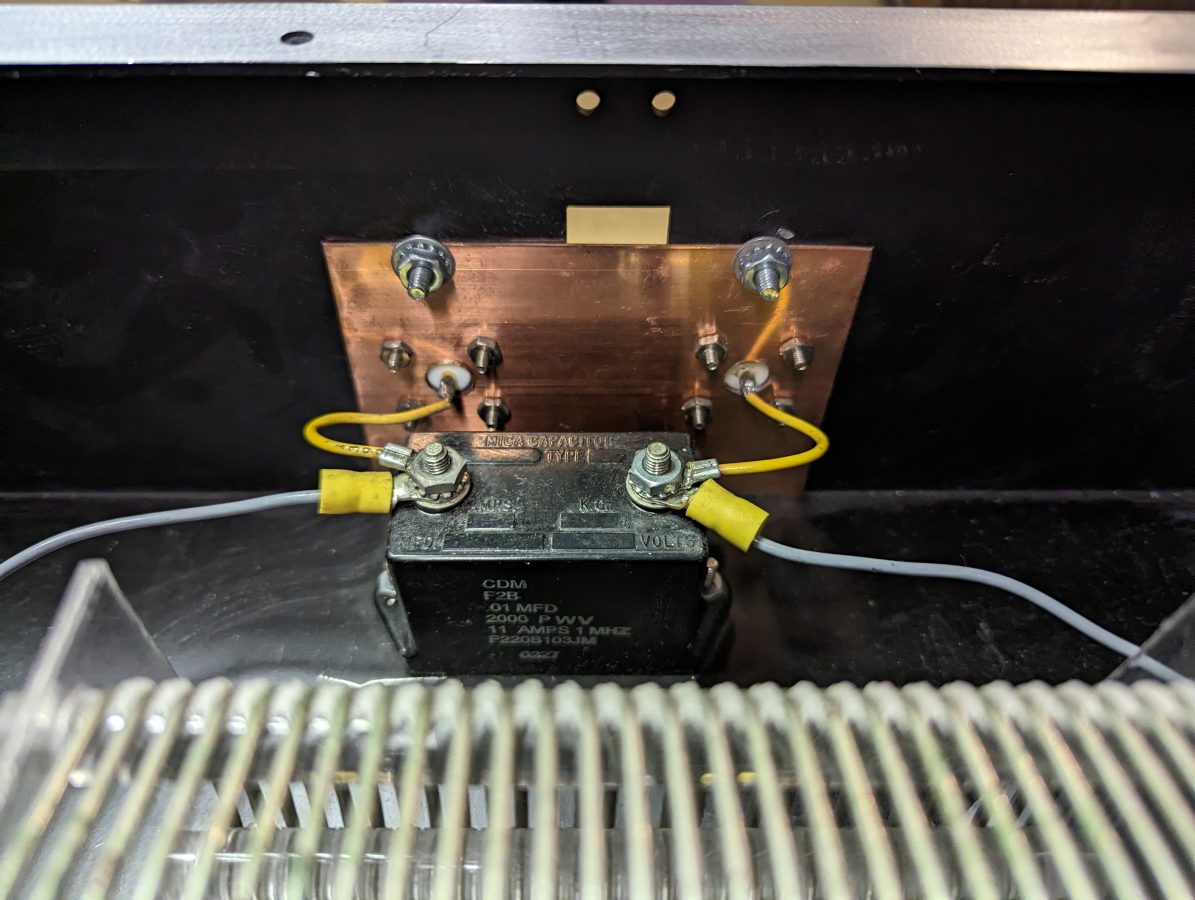
CDM F2B 0.01 uF capacitor with back of N connector inputs

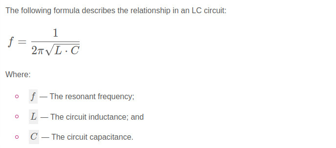
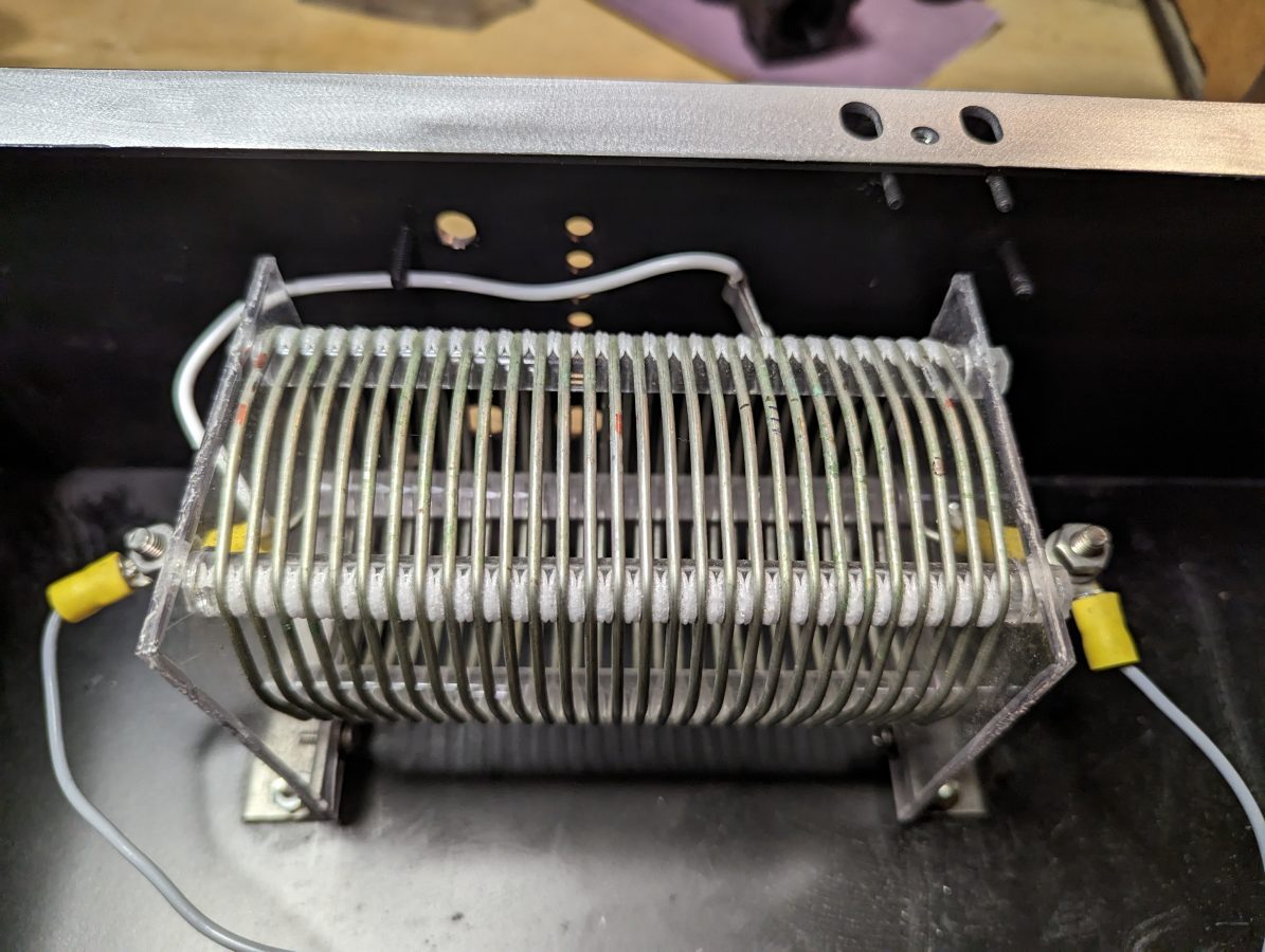
Finding a type F2B 0.01 uF capacitor, rated at 2000 volts and 11 amps, the value of the inductor was calculated. For the inductor, a 20 uH coil with taps will work great. For receive-only applications, much smaller-sized components can be chosen. Also, there are many bandstop filters with multiple poles. Those are great, but I like the simplicity of the parallel resonant LC circuit.

20 uH inductor salvaged from Energy Onyx transmitter

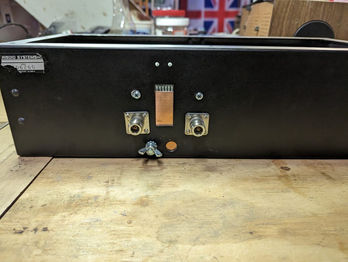
The N connectors were salvaged from I don’t know where and the enclosure used to house a power supply for a Radio Systems console.

N connectors for input and output.

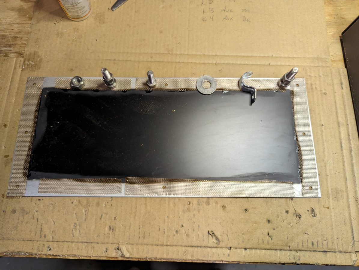
For shielding, I sanded the paint off of the enclosure where the lid is attached and tacked some brass screen down with gorilla glue. This will make a good RF contact surface. The outer of the N connectors are bonded to a piece of copper ground strap which also has a grounding lug on it.

Enclosure lid with brass screen to make contact

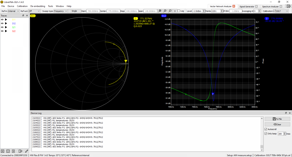
I used the Libra VNA to tune it up:

S12 shows return loss, S21 shows Phase

The scan shows it is -31 dB on the carrier frequency. It is -17 dB on 760 KHz and -20 dB on 780 KHz. This is good, because I may still want to listen to the station on the remote receiver. According to the smith chart, it is actually resonant on 771.5 KHz, but that is close enough for this application. I think the resonance went up slightly when I put the cover on after the tune-up.

There are several tank circuit calculators online. It is best to have more capacitance and less inductance to keep the Q of the circuit low and suppress the sidebands as well as the carrier.

Vagabond Able; The story of the USCGC Courier

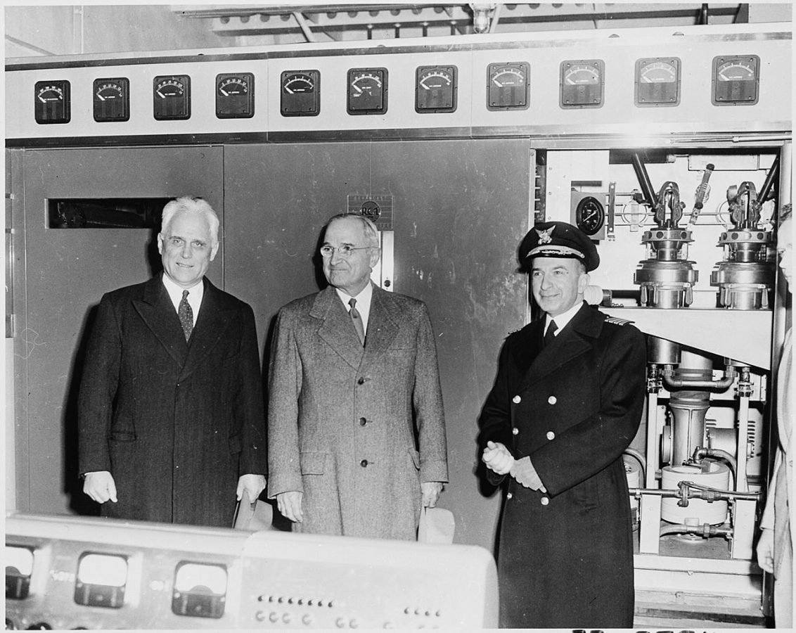
The VOA and shortwave broadcasting story is interesting from an engineering perspective. Over several decades, the US government spend many millions of dollars building out transmitter sites both overseas and in the continental US to transmit information behind the iron curtain. The Coast Guard Cutter Courier WAGR-410 was a converted cargo ship fitted out with an RCA 150 KW Medium Wave transmitter on 1259 kHz and two Collins 207B1 35KW shortwave transmitters in the cargo hold.

President Truman standing in front of an RCA BT-150, 150 KW AM transmitter on board USCGC Courier, 1952.

The ship had various wire aerials, including the Medium Wave antenna supported by a barrage balloon.

From September of 1952 until 1964, The Courier was anchored primarily off of Rhodes, Greece broadcasting programs into the Soviet satellite states in eastern Europe and the Soviet Union itself. This arrangement made it difficult to jam, although expensive to support and maintain.

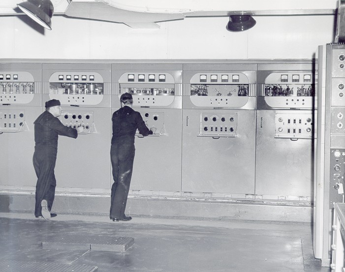
Coast Guard guys, operating a Collins 207B1 Shortwave Transmitter

It was, however, just one of the methods of broadcasting used.

Through the 1950s and 1960s, VOA, Radio Free Europe, and Radio Liberty built extensive sites in Bilbus Germany, RARET in Portugal, Tangiers, Tinang in the Philippines, Morocco, Udon Thailand, Greenville Site A and B in North Carolina, Dixon and Delano California, Bethany Ohio, etc. Many of these sites supported multiple curtain arrays, rhombic antennas used to receive programming, generators, living facilities, etc. In other words, no expense was spared.

In Rhodes, Greece; eventually the transmitting equipment from the CGC Courier was transferred ashore as a VOA relay site. The Courier then returned home.

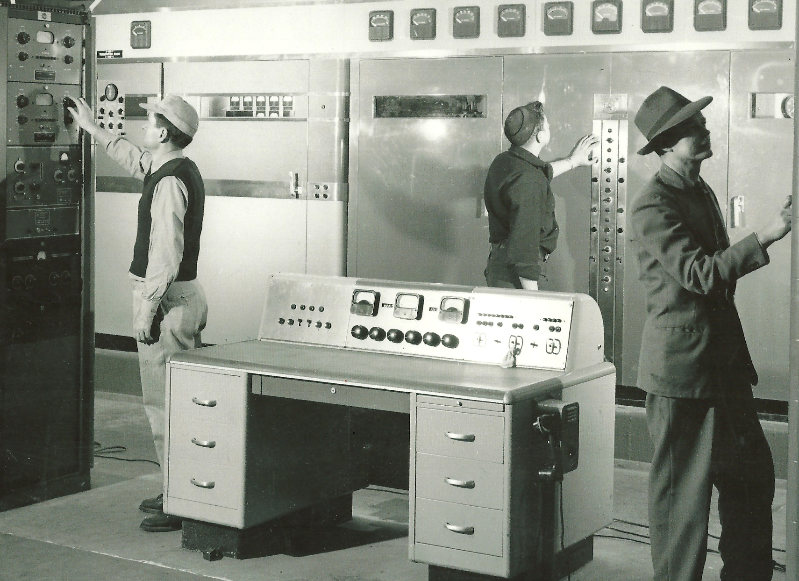
Transmitter control operator position, USCGC Courier

The point of the story; a lot of time, effort, and money went into broadcasting information to the Soviet Union and its satellite states over the period of four decades. From what I am told (by people who lived through that time period), the payoff really occurred in 1986, when the Chernobyl nuclear power plant accident happened. State-run Soviet radio and television were broadcasting Swan Lake, while RFE/RL had useful information including where the worst of the radiation was spreading, the wind direction, and how to protect humans from radiological hazards. For many average Soviet citizens, this was the tipping point and the collapse of the Soviet Union was inevitable from that point forward.

After the fall of the Soviet Union, many of these sites were shut down and the facilities were torn down because the cold war was over. Shortwave broadcasting was seen as expensive and unnecessary. Unfortunately, many warning signs were missed along the way and the present occupant in the Kremlin has wild dreams of a New Russian Empire. To revive shortwave in the 2020s would require another monumental and sustained effort starting with getting good receivers into the right hands. Shortwave broadcasts could become an alternative information source, especially if the Russia-Ukraine war becomes a protracted draw. However, it is not simply a matter of turning a few transmitters on and scheduling some Russian language programming.

Could the Russian state propaganda machine be engaged and defeated; yes. Will it be quick and easy; no. Is it worth it; yes. The real problem is apathy. The Russians have been subjected to terrible governance since pretty much the beginning of their existence. How to overcome that apathy and the corresponding sense of helpless victimhood of the Russians themselves is the question.

Regarding Vagabond-Able, after the USCGC Courier returned to the US, it was used as a training ship until 1972, when it was decommissioned.

USCGC Courer WATR-410/NFKW

Disinformation and Shortwave radio

I came across an interesting article on the Engineering and Technology website:

How to defeat disinformation with short-wave radio

The takeaway is this:

“When you’re in an environment where infrastructure has been damaged, where transmission towers have been destroyed or where the power supply to the transmission equipment isn’t reliable and robust, such as some parts of Ukraine, then you end up with a fallback to older equipment, such as battery-powered radios,”

Griffiths, Sarah. “How to Defeat Disinformation with Short-Wave Radio.” RSS, The Institute of Engineering and Technology, 9 Nov. 2022, https://eandt.theiet.org/content/articles/2022/11/how-to-defeat-disinformation-with-short-wave-radio/.

That applies not only to war zones but also to natural disasters or other situations where widespread disruptions occur in communications or power distribution networks.

The article focuses mainly on the BBC’s efforts to get information to Ukrainians who may be listening on shortwave radios in occupation zones. That is an effective use of shortwave radio, to be sure. One problem with this idea; if there are no regularly used shortwave frequencies in the affected areas, who will have access to a shortwave radio? There may be a few receivers around in any given community, but the vast majority of people will not have access to them. The idea that a broadcast service can be neglected for years if not decades, then be quickly dusted off and put into use is simply not realistic. This applies to AM and FM radio as well.