This Onan 30OEK propane-powered generator has been in service for 39 years at a transmitter site where the power goes out often. It has a lot of hours on it. The hour meter stopped working about 15 years ago, but the hours back then were 1097.
In addition, the main shaft seal started leaking oil about 10 years ago, creating an oily blowback mess every time the generator ran for more than a few hours. The block heater went bad, the battery charger overcharged then exploded the battery splashing sulfuric acid all over the housing and engine block.
The last power outage was the final one. It ran for a few hours then faulted. When the local engineer tried to restart it, it was never able to get to speed and was misfiring badly. Below appeared a large and spreading puddle of engine oil.
As this station is one of the major money makers for the owner, a replacement generator was obtained.
Cummins RS50 50 KW Propane powered generator
This is larger than the old generator. The good news; now the AC can be put on the generator to keep the room cool. In the past, the backup cooling fan was used when on generator power, which sucked dirt, bugs, and pollen into the room.
It will also have considerable headroom for any additional loads that may be installed in the future.
The generator in place and leveled
We had to enlarge the opening for the radiator and put in some steel angle for the lintels.
Exhaust piped outside with the radiator air
The first start run and load test went well. I ran it for about 30 minutes under full load, enough time to burn the paint off the exhaust manifold. Seems like a pretty solid unit. With the power conditions at this site, it will get a lot of use.
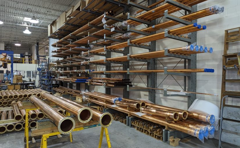
Update: This post is from several years ago (January 31, 2018), however, I did a fairly major revision and added a lot of information, so I am bumping it to the top of the pile. The header picture is from the Myat facility in Mahwah, New Jersey.
Installing transmitters requires a multitude of skills; understanding the electrical code, basic wiring, RF theory, and even aesthetics play some part in a good installation. Working with rigid transmission line is a bit like working with plumbing (and is often called that). Rigid transmission line is often used within the transmitter plant to connect to a four-port coax switch, test load, backup transmitter, and so on. Sometimes it is used outside to go up the tower to the antenna, however, such use has been mostly supplanted by Heliax-type flexible coax.
We completed a moderate upgrade to a station in Albany; installing a coax switch, test load, and backup transmitter. I thought it would be interesting to document the rigid line work required to complete this installation. The TPO at this installation is about 5.5 KW including the HD carriers. The backup transmitter is a Nautel VS-1, analog only.
This site uses a 1 5/8-inch transmission line. That line is good for most FM installations up to about 10-15 Kilowatts TPO. Beyond that, 3-inch line should be used for TPOs up to about 30 Kilowatts. Above 30 KW TPO, 4 inch or greater line is required. There are a few combined FM stations that are pumping 80 or 90 KW up to the antenna. Those require 6 inch or greater line. Even though the transmission lines themselves are rated to handle much more power, reflected power often creates nodes along the line where the forward power and reflected power are in phase. This can create hot spots and if the reflected power gets high enough, flashovers.
This brings up another point; most rigid line comes in 20-foot sections. There are certain FM frequencies that require different lengths due to the aforementioned nodes that fall along the 1 wavelength intervals. If one of those nodes happens on a flange, that could create problems.
Frequencies between 88.1 and 95.9 MHz, use 20-foot line sections
Frequencies between 96.1 and 98.3 MHz, use 19.5-foot line sections
Frequencies between 98.5 and 100.1 MHz, use 19-foot line sections
Frequencies between 100.3 and 107.9 MHz, use 20-foot line sections
TV frequencies are much more complicated. The large channel width and much larger spectrum use means that close attention needs to be paid to line section length. Since low-power TV and translators may need to change frequency, those stations often use Heliax instead of rigid line.
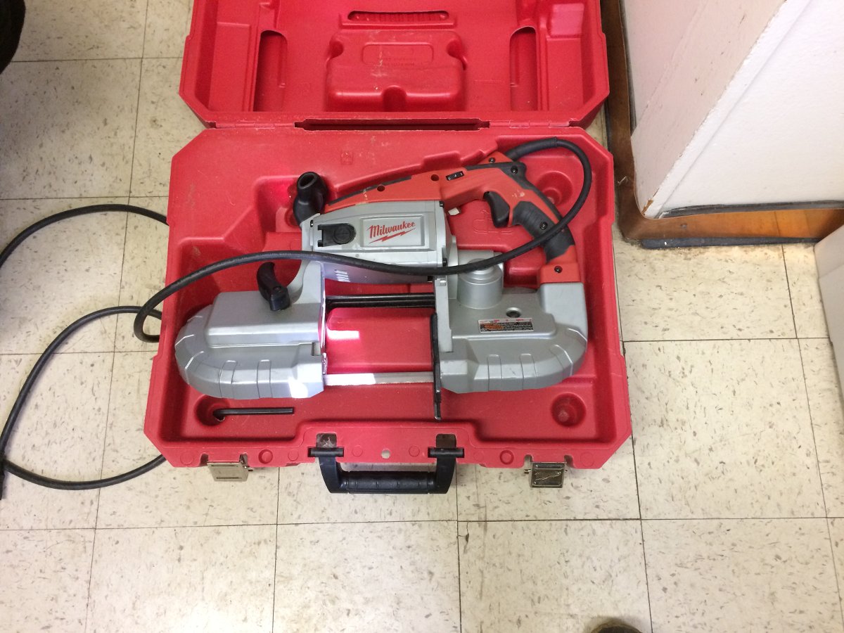
Milwaukee portable band saw
Working with rigid line requires a little bit of patience, careful measurements, and some special tools. Since the line itself is expensive and the transmission line lengthener has yet to be invented, I tend to use the “measure twice and cut once” methodology.
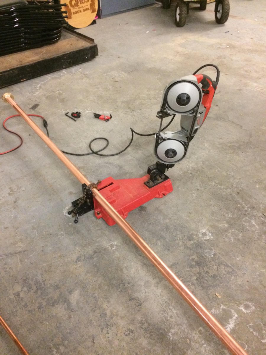
For cutting, I have this nice portable band saw and table. I bought this particular tool several years ago and it has saved me hours if not days of work at various sites. I have used it to cut not just coaxial line and cables, but uni strut, threaded rod, copper pipe, coolant line, conduit, wire trays, etc. If you are doing any type of metalwork that involves cutting, this tool is highly recommended.
Milwaukee 6230N Band Saw with cutting table
There are now Lion battery types of bandsaws which are certainly more portable than this. Still, the table with the chain clamp makes work much easier and the cuts are straight (perpendicular), which in turn makes the entire installation easier.
The next point is how long to cut the line pieces and still accommodate field flanges and inter-bay line anchors (AKA bullets).
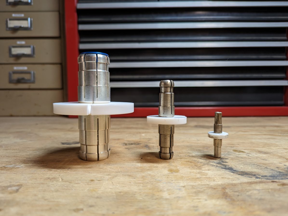
Inner bay line anchor, aka “bullet” 3 1/8 inch, 1 5/8 inch, and 7/8 inch respectively
The inner conductor is always going to be shorter than the outer conductor by some amount. Below is a chart with the dimensions of various types of rigid coaxial cables.
When working with 1 5/8 inch rigid coax, for example, the outer conductor is cut 0.187 inches (0.47 cm) shorter than the measured distance to accommodate the field flange. The inner conductor is cut 0.438 inches (1.11 cm) shorter (dimension “D” in the above diagram) than the outer conductor to accommodate the inter-bay anchors. These are per side, so the inner conductor will actually be 0.876 inches (2.22 cm) shorter than the outer conductor. Incidentally, I find it is easier to work in metric as it is much easier to measure out 2.22 CM than to try and convert 0.876 inches to some fraction commonly found on a tape measure. For this reason, I always have a metric ruler in my tool kit.
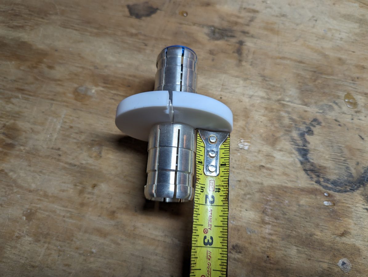
If you do not have a handy chart, you can estimate the inner conductor length by measuring the inner bay anchor from the insulator to the first shoulder. Then multiply by two.
Measuring inner bay line anchor
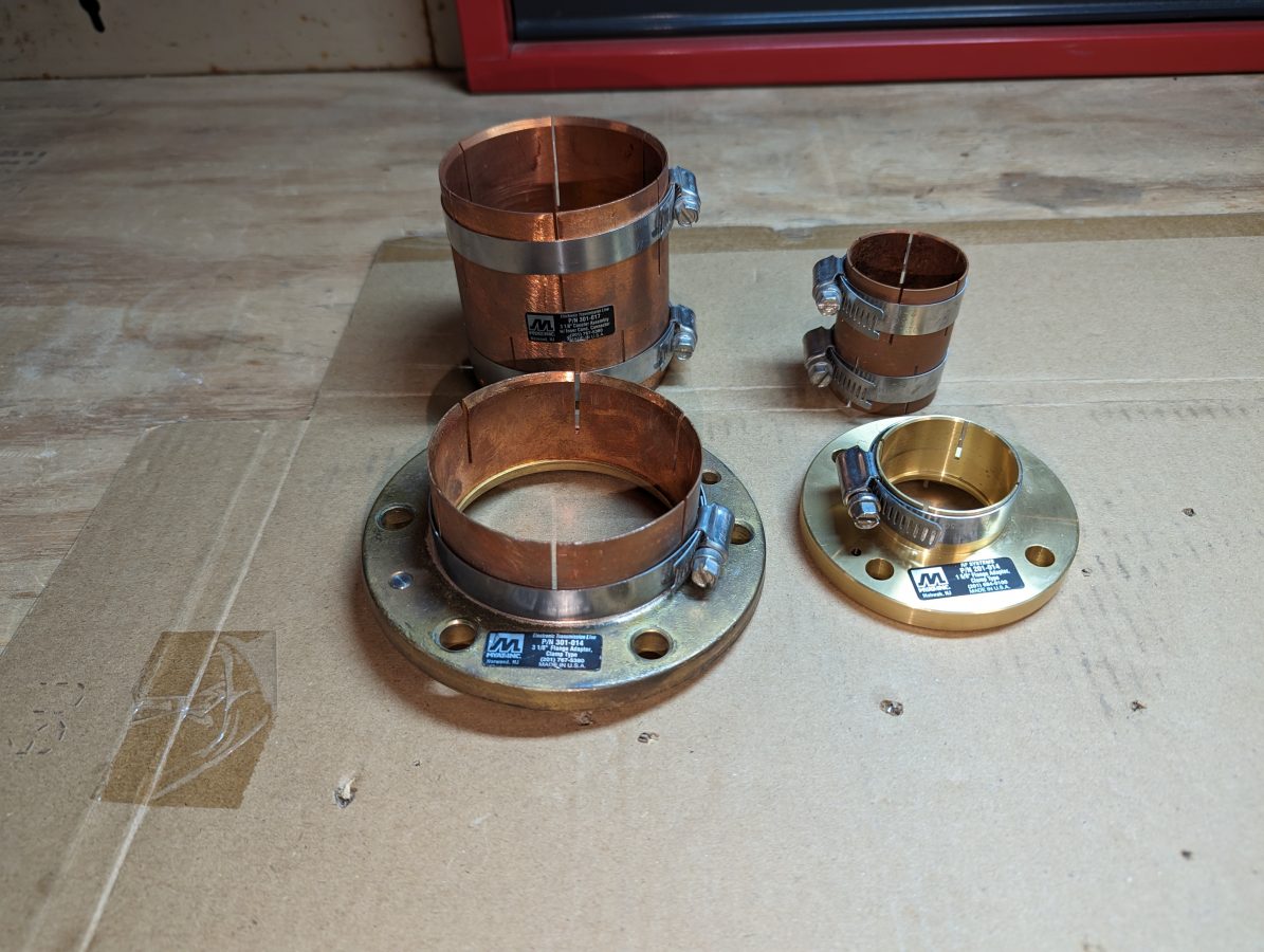
In this case, the measurement from insulator to shoulder is 11/16th of an inch (17.5 mm). If Clamp On Flange adaptors (AKA field flanges) are being used, don’t forget to account for the small lip (usually less than 1/16th of an inch) around the inside of the flange where the outer conductor is seated. If you are using unflanged couplings instead of field flanges, then you can disregard this.
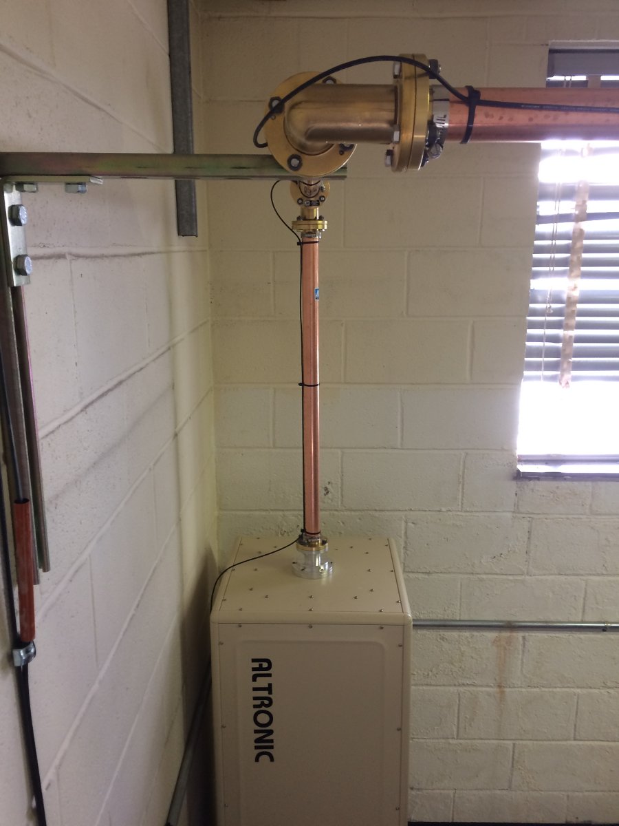
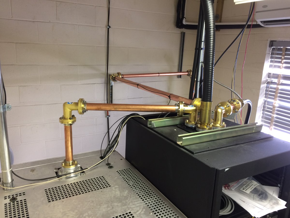
Clamp on Flange adaptors in the front, flangeless couplers in the back1 5/8 inch rigid coax run to Altronic air-cooled 20 KW test load1 5/8 inch rigid coax and 4 port coax switch mounted on top of Middle Atlantic Rack
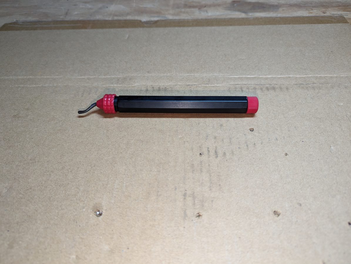
The next step is de-burring. This is really critical at high power levels. I use a copper de-burring tool commonly used by plumbers and electricians.
De-burring tool, can be found in the plumbing isle of most big box hardware stors
One could also use a round or rat tail file to de-bur. The grace of clamp-on field flanges is they have some small amount of play in how far onto the rigid line they are clamped. This can be used to offset any small measurement errors and make the installation look good.
After a bit of reflection and a few good conversations over the New Year’s Holiday, I decided that I should continue my work on this blog. I would like to thank all those that have stuck by and waited. I have received numerous emails and messages offline, all of which have been read and appreciated.
Since the abrupt stoppage last July, which was absolutely necessary for me, many things have happened within the business. Fortunately, during the hiatus, I was still taking pictures. After sorting through them, here are a few interesting things that happened:
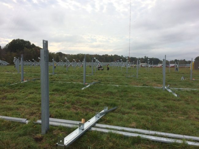
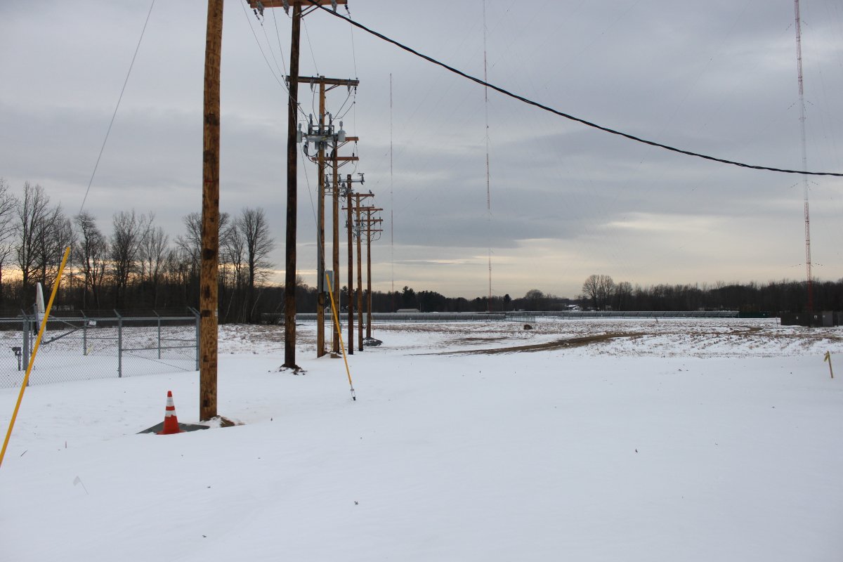
WROW-AM Steel mounting poles on antenna array field
This project required many steel mounting posts to be driven into the ground around the AM towers. I don’t even know how many, but I would hazard a guess of over three hundred. Each one of those mounting posts was hand-dug down a depth of 6-10 inches to look for ground wires. Where ever a ground wire was found, it was moved out of the way before the post was set.
WROW-AM ground wire moved out of way
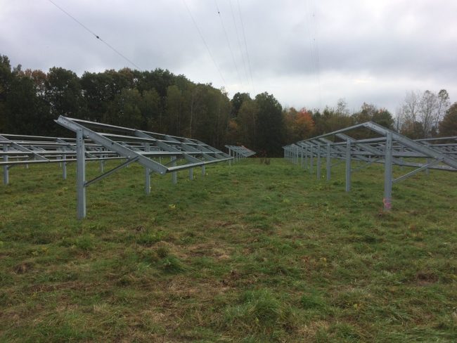
Basically, the solar array covers about 1/2 of the antenna array field. All of the steel mounting hardware is tied into the ground system, making, what I am sure is a pretty large above-ground counterpoise.
WROW-AM solar panel mounting hardware
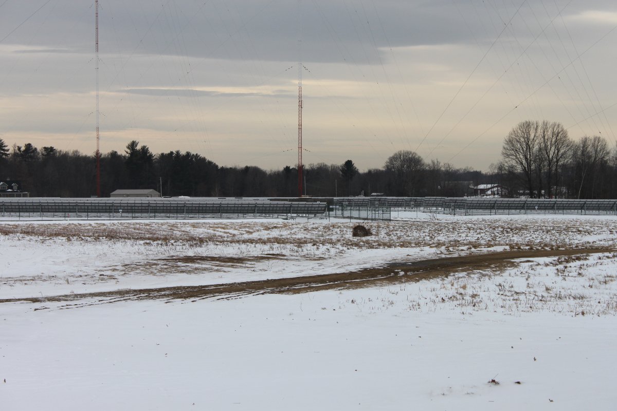
View from the south looking north:
Solar Array installed on WROW antenna array, Glenmont, NY
View from the north, outside of the transmitter building, looking south:
Solar Array installed on WROW antenna array, Glenmont, NY
Power company interface and disconnect:
Solar Array utility company disconnect, Glenmont, NY
The utility company had to upgrade the transmission lines to the nearest substation to handle the additional power produced by the solar system. All in all, it was a fun project to watch happen.
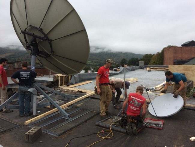
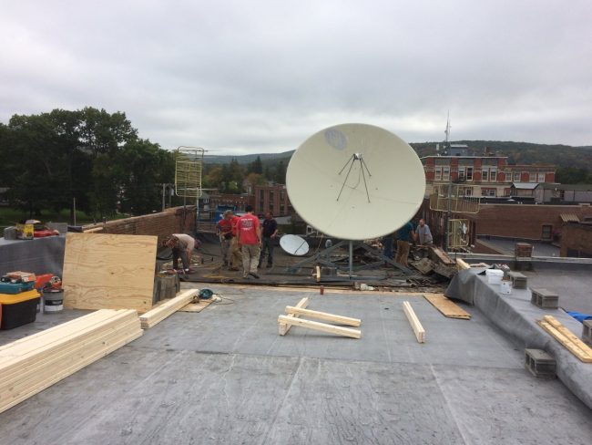
At a certain studio building, which is over 150 years old, the roof needed to be replaced. This required that the 3.2-meter satellite dish and non-penetrating roof mount be moved out of the way while that section of the roof was worked on.
3.2 meter satellite dish
Dish was ready to move, and all of the concrete ballast was removed and taken down from the roof. The roofing contractors constructed a caddy and the entire dish and mount were slid forward onto the area in front of it. Since the front part of the roof was not reinforced to hold up the satellite dish, we did not ballast the mount and the XDS receivers ran off of the streaming audio for a couple of days until the dish was put back in its original position.
3.2 meter satellite dish ready to move
A couple of other studio projects have been underway in various places. Pictures to follow…
One of our clients sold their radio stations to another one of our clients.
There has also been a bankruptcy of a major radio company here in the good ol’ US of A. Something that was not unexpected, however, the ramifications of which are still being decided on in various board rooms. One of the issues as contractors is whether or not we will get paid for our work. All things considered, it could be much worse.
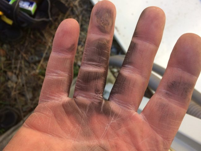
Learned a valuable lesson about mice chewed wires on generator battery chargers. I noticed that the battery charger seemed to be dead, therefore, I reached down to make sure the AC plug was in all the way. A loud pop and flash followed and this was the result:
Arc burns, right hand
My hand felt a bit warm for a while. The fourth digit suffered some minor burns. There is at least one guy I know that would be threatening a lawsuit right now. Me, not so much… All of the high voltage stuff we work on; power supplies that can go to 25 KV, and a simple 120 VAC plug is the thing that gets me.
The return of the rotary phase maker.
Rotary phase maker, Kay Industries T-10000-A
Mechanically derived 3rd phase used when the old tube type transmitter cannot be converted to single phase service.
Those are just a few of the things I have been working on. I will generate some posts on current projects underway. Those projects include a 2 KW FM transmitter installation, another studio project, repair work on a Harris Z16HD transmitter, etc
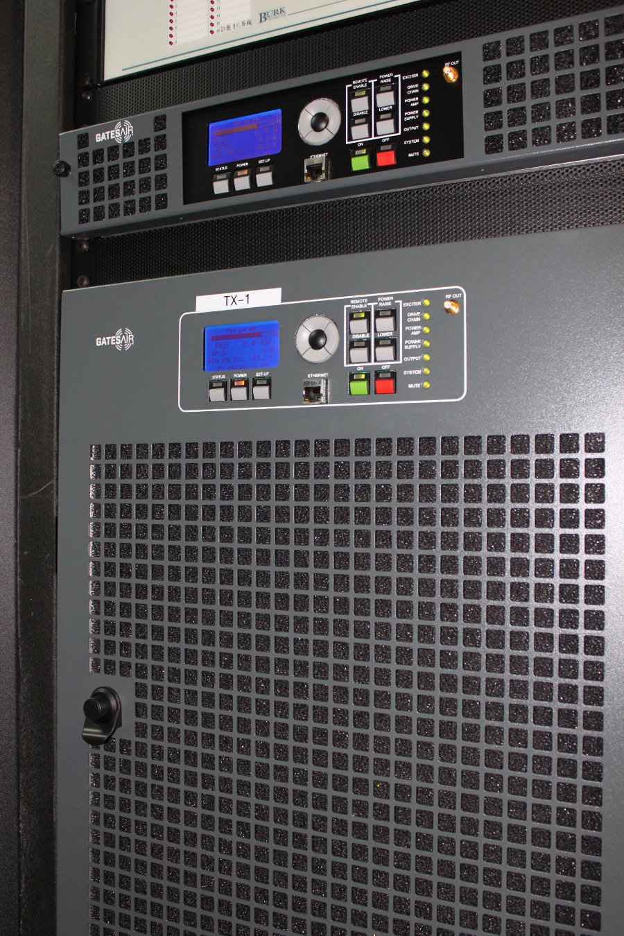
This is the second Gates Air FAX-10 that I have installed. This one is in the shipping container transmitter site from the previous post of the same name. In this case, we dispensed with the equipment rack that came with the transmitter and installed it in a standard Middle Atlantic rack. The Harris rack configuration wastes a lot of space and since space is at a premium, we decided to do it our own way.
Gates Air FAX-10 in Middle Atlantic rack
The bottom of the rack has the transmission line dehydrator. The top of the rack has the Dielectric A60000 series 1 5/8 inch coax switch, a Tunwall TRC-1 switch controller, and the Burk ARC-16 remote control. I cut the rack panel top to accommodate the coax switch. The racks were removed from an old studio site several years ago and have been in storage since then.
Gates Air FAX-10
The Gates Air FAX-10 transmitter on the air, running a sports-talk format.
Dummy load and Broadcast Electronics FM10B transmitter
View from the other side showing the test load and BE FM10-B transmitter. This transmitter had a problem that I have run into before with BE FM transmitters. The jumper between the exciter and IPA had the wrong phase rotation causing reflected power. I added a foot to its length and that problem disappeared.