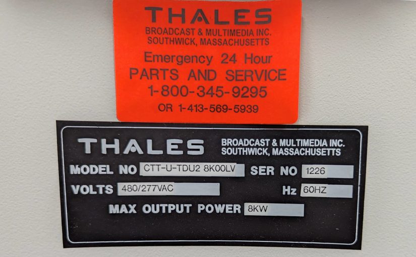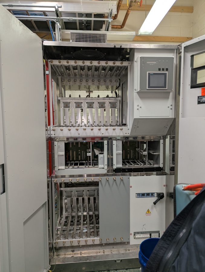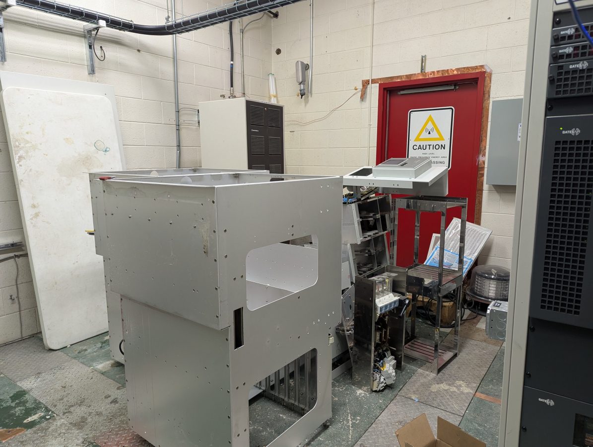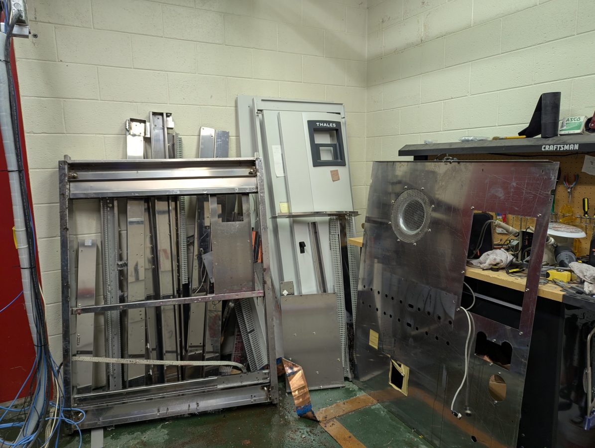
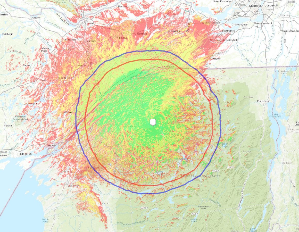
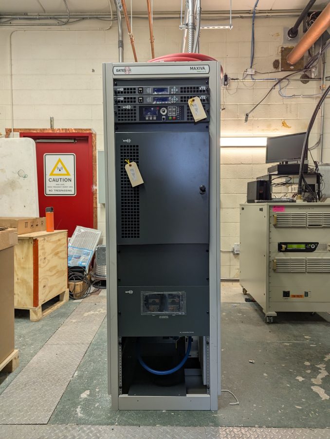
The public TV viewers in the St. Lawrence Valley get an updated transmission system. I recently finished installing this GatesAir ULXTE-6 transmitter in South Colton, NY. That is way up on the very northern fringes of the Adirondack Mountains. It replaces the Thales CCT-U-TDU2 8KW UHF TV transmitter, which was installed around 2004, early on during the analog/digital TV conversion.
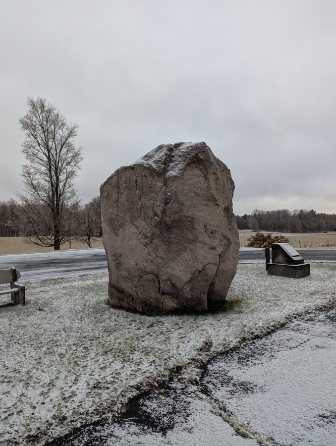
South Colton, NY is home of Sunday Rock. According the the historical marker:
This glacial bolder (erratic), twice preserved by local citizens, marks the gateway to the “Great South Woods.” In frontier days it was said that there was no law or Sunday beyond this point. May all who pass this way continue to enjoy the beauty of the mountains.
This in the northern end of the lake effect snow belt, where the average yearly snowfall tops 6 to 10 feet. Sometimes there is continuous snowfall starting in November and ending when Lake Ontario finally freezes in late January or February.
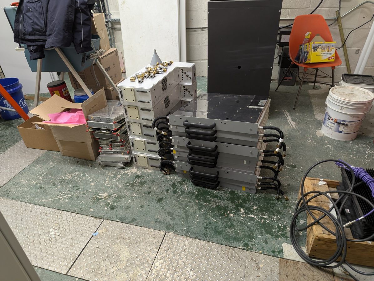
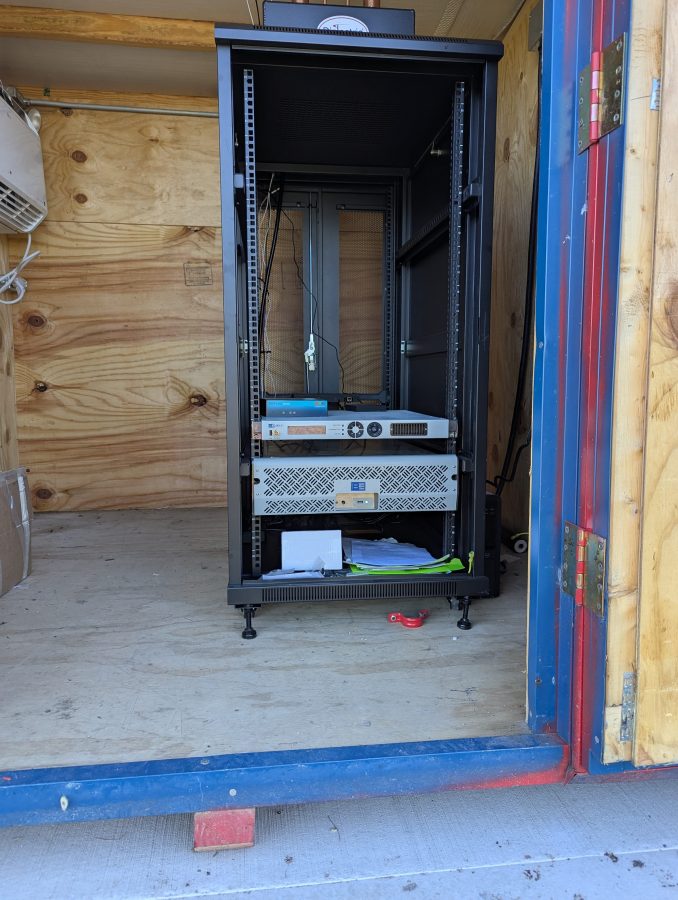
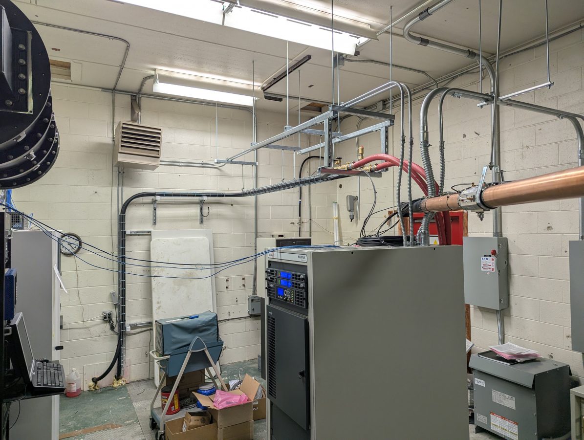
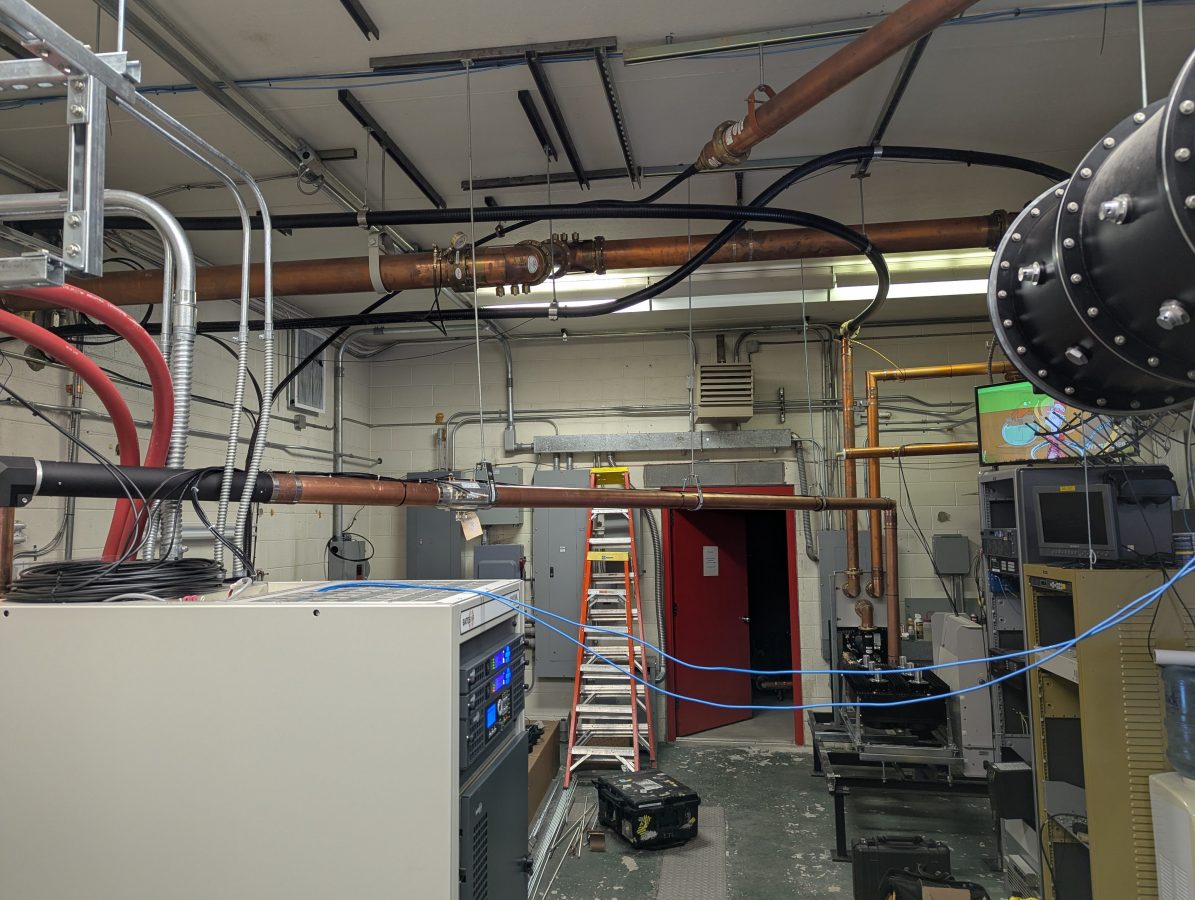
Back to the business at hand; the new transmitter placed:
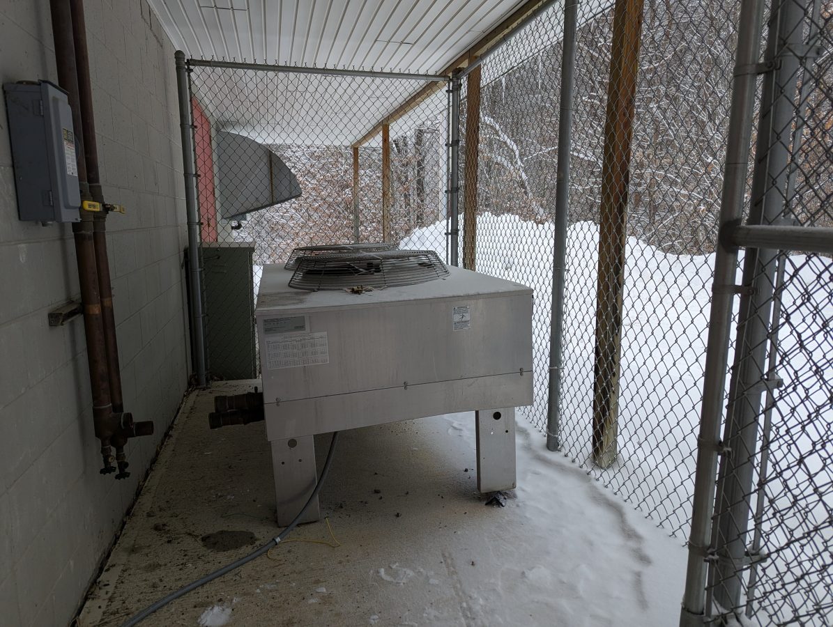
The 25 KW heat exchanger was placed where the old analog heat exchanger was:
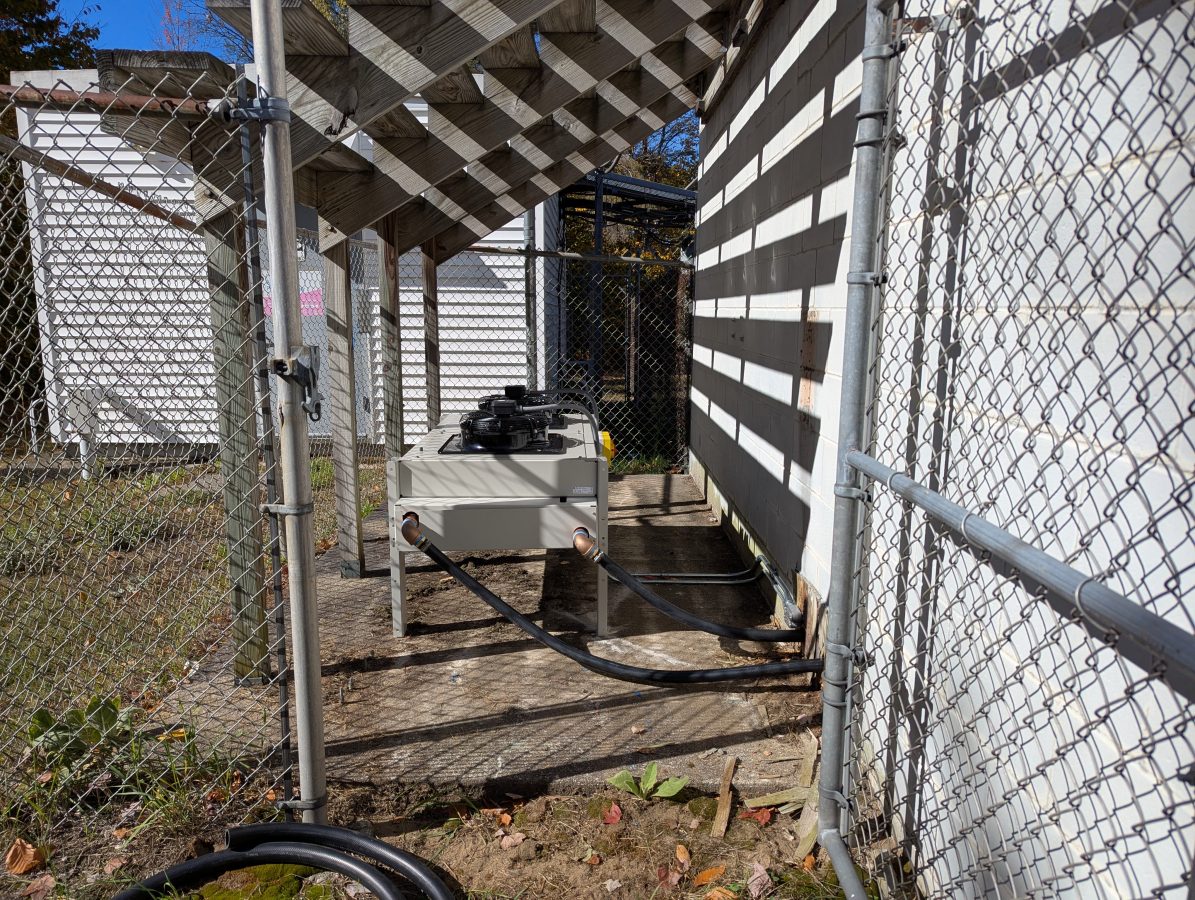
This system uses 1 1/4 inch flexible tubing, which is easier to work with than the 1 1/2 inch steel reenforced tubing.
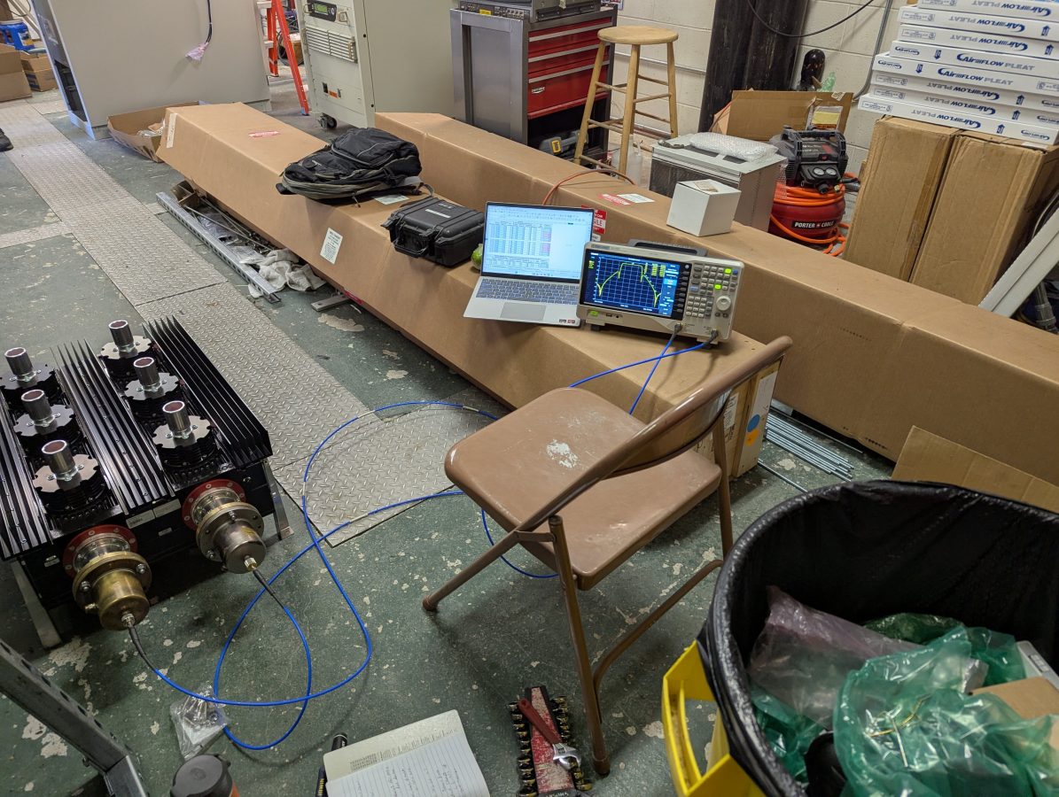
Measuring the Comtech mask filter with the network analyzer:
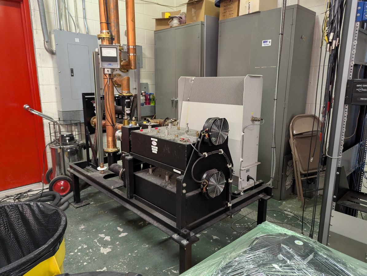
New mask filter mounted on the old dielectric mask filter stand:
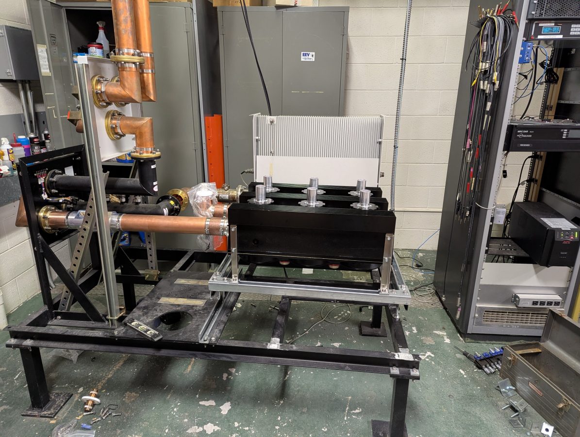
This arrangement allows for the reuse of the two coax patch panels, on for antenna/dummy load, the other for main antenna/backup antenna.
Post mask filter RF signal analysis using a Rohde Schwarz ETL:
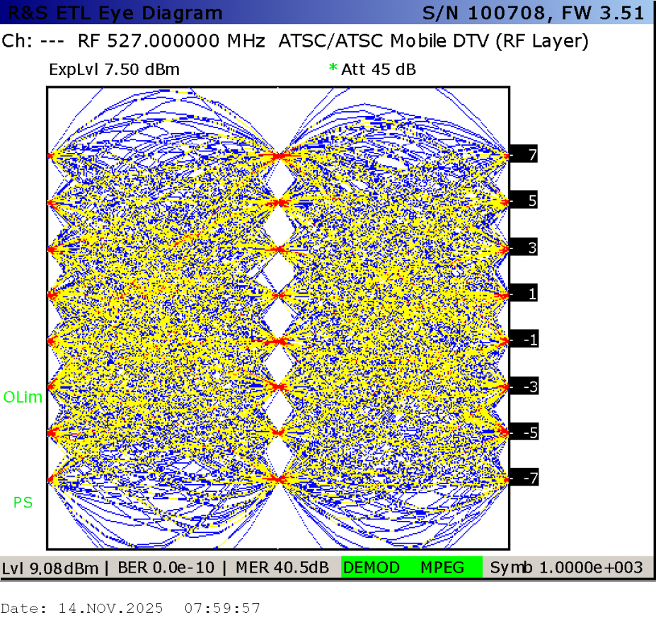
The GatesAir equipment always has good performance parameters.
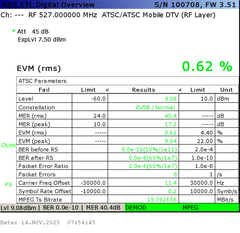
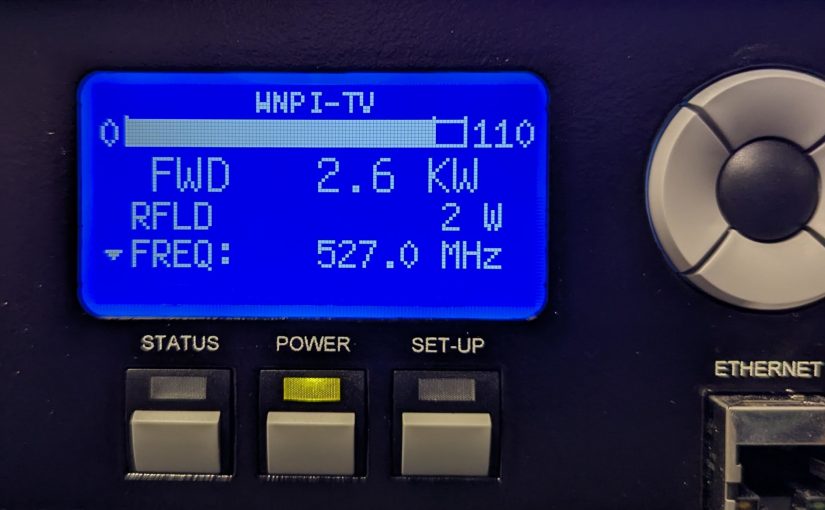
The carrier frequency is measured using the pilot. In this case, both exciters have the GPS reference connected and working. I think the ETL OCXO might be 11 Hz low.
Anyway, this was a fun project.