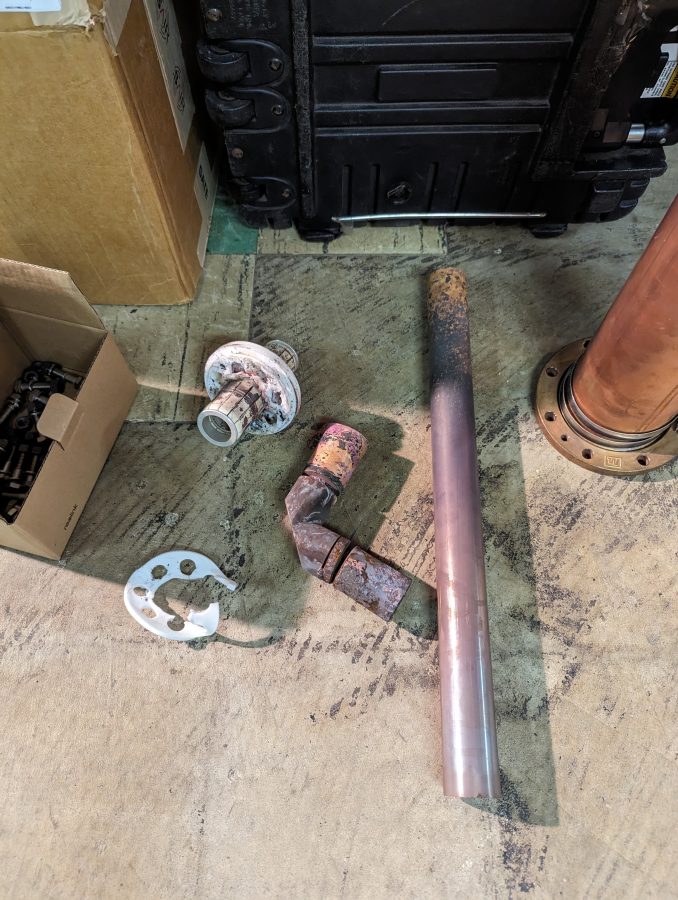
GatesAir contracted me to go to Utica, NY, and do some repair work. WKTV has a ULXTE-50 UHF transmitter which burned out an RF elbow between the UHF combiner in cabinet 1 and the UHF low pass filter for cabinet 1.
Burned-out RF parts3 Port UHF combiner, cover removed for cleaning
There was a bunch of burned debris in the bottom; little bits of melted metal and plastic.
Bottom of UHF combiner
We first vacuumed out as much stuff as we could get. Then used an air compressor to blow the rest out and wiped everything down with clean rags and Windex.
Once that was done, the unit was reassembled and reinstalled in the transmitter. A new elbow, UHF low pass filter, and direction coupler were installed and the transmitter powered back up.
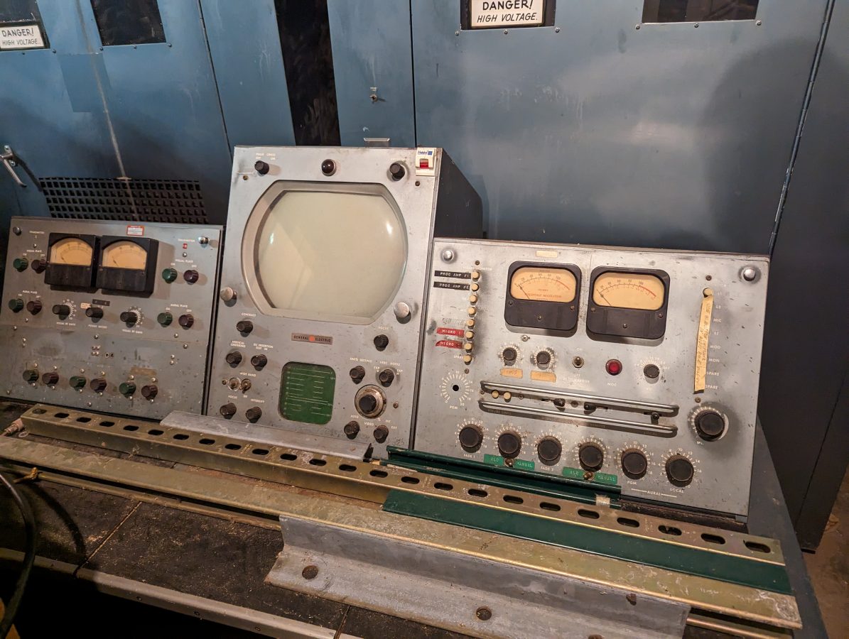
The transmitter site is actually located north and slightly west of Little Falls, NY. The station has been on the air since 1949 and the original GE transmitter is still in the garage. It was difficult to squeeze in and get a look at the transmitter, however, the operator’s console was out in the open:
GE TV control operator’s console, circa 1949
In most places, this would have been thrown out years ago. Now, it is a museum piece. Lots of interesting history in the Wikipedia article, too.
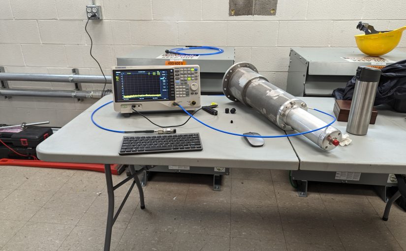
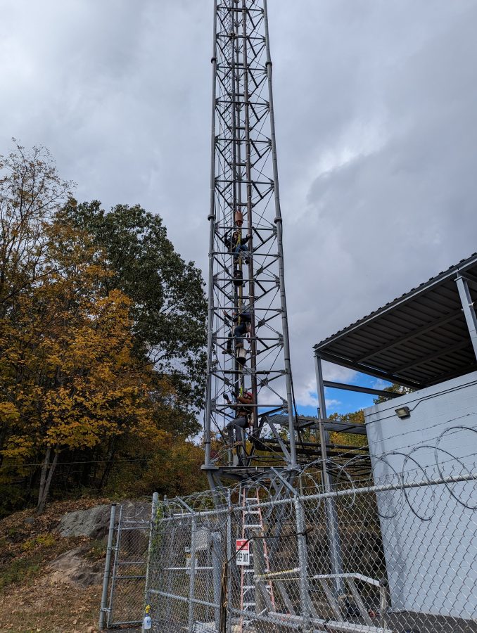
We have been really busy this fall working on multiple projects plus the day-to-day tasks. One thing that is always fun; sweeping antennas with a VNA.
In this case, WVIT Hartford, CT needed to repair a leaking transmission line section just below the antenna. To ensure that there would be no problems with return to the air at full power, we did a before sweep and after sweep.
WVIT is the ATSC 3.0 lighthouse station for the Hartford Market. FCCinfo.com has the station listed as ATSC 3.0.
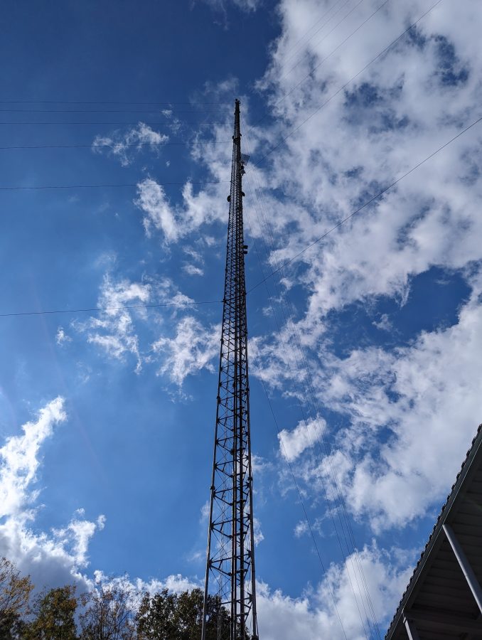
WVIT Tower, Hartford CT
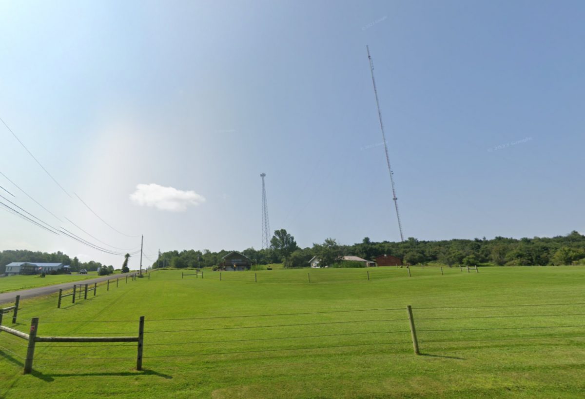
The WVIT tower is 1,100 feet tall and is located on Rattlesnake Mountain near Farmington, CT. Most of the other Hartford TV stations are on the same hill.
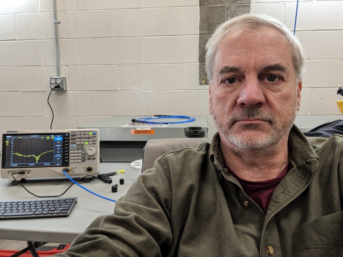
Tower crew, hitching a ride to the topSelfie; return loss looks good
It is always interesting to see new places and meet new people. This site has an auxiliary TV studio, which they were using during COVID.
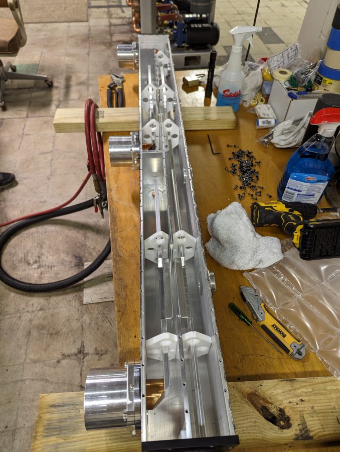
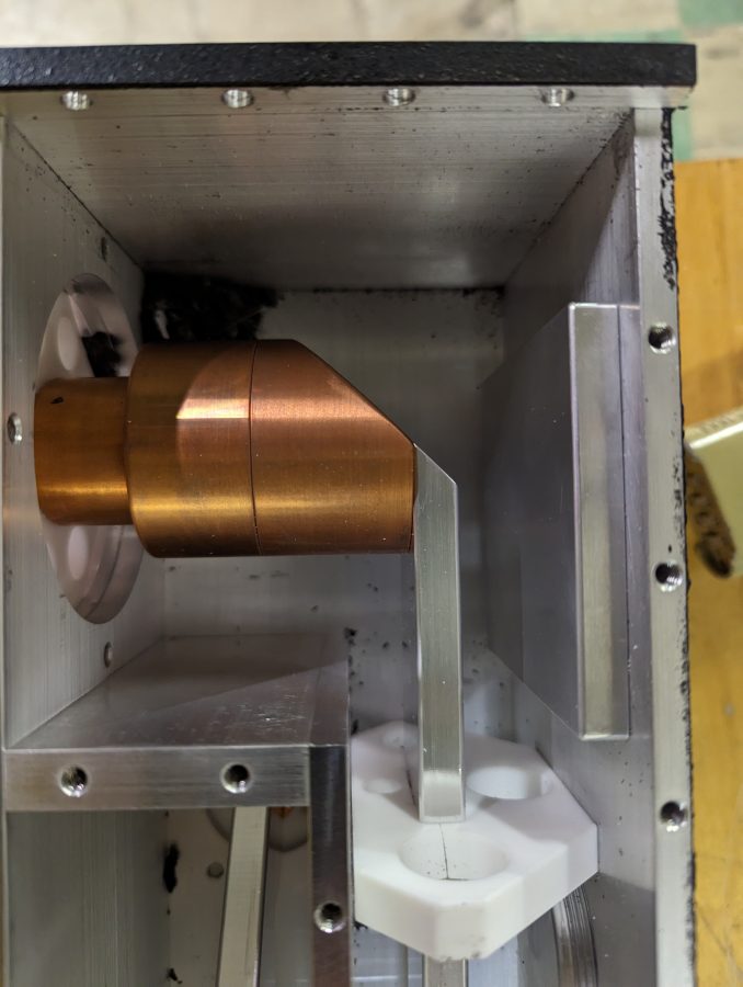
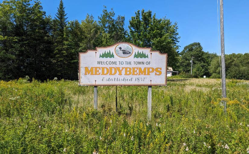
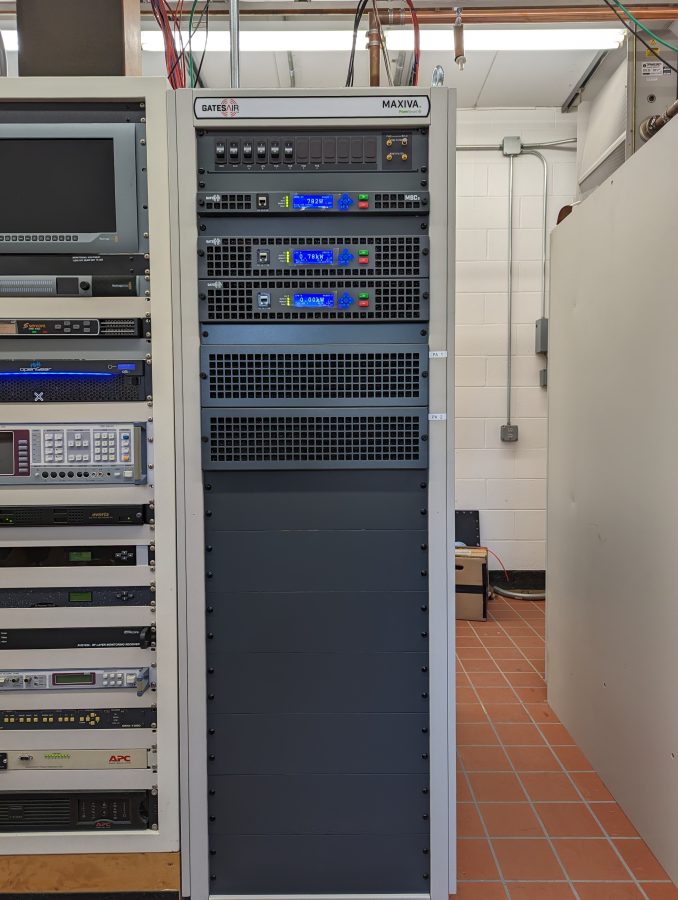
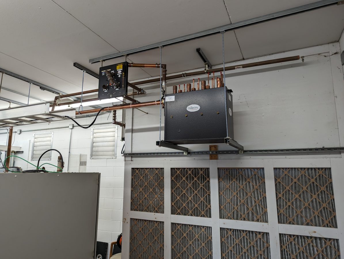
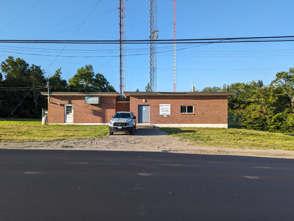
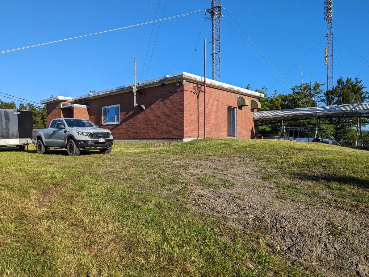
I might not know that if I hadn’t been there installing a TV transmitter. We installed this GatesAir VAXTE-2 for Maine Public Broadcasting’s WMED-DT.
GatesAir VAXTE-2, WMED-DT Meddybemps, MaineDielectric 8 pole channel mask filterWMED transmitter site
After the old Harris Platnum transmitter was turned off, the client got a call from the cable company across the border in New Brunswick. Apparently, they take the off-air signal for their cable feed of PBS in New Brunswick.
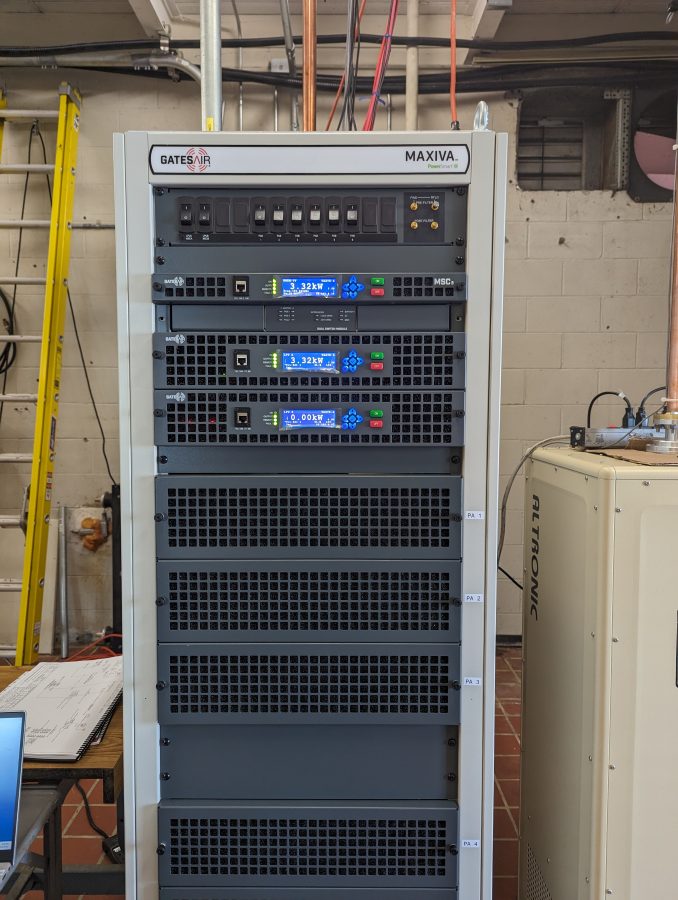
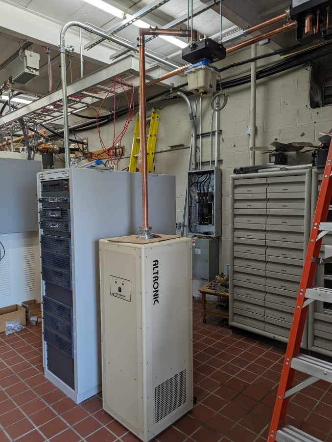
We also installed a VAXTE-6 at Mars Hill for WMEM-DT.
GatesAir VAXTE-6, WMEM-DT, Mars Hill, MaineWMEM-DT test load and coax switchWMEM Transmitter site, Mars Hill, Maine
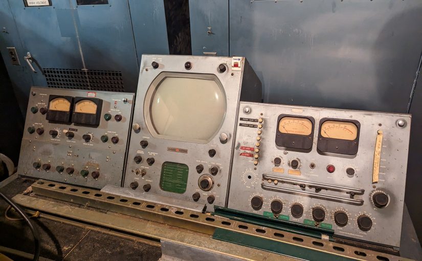
I was reading through the SBE 2023 salary survey and noticed that those engineers who work in Radio and TV make more money than those who do just radio. My experience is that TV is more technically challenging because there are many more building blocks that go into the end product. ATSC has several layers of complexity starting with video and audio codecs. Then there are various transport methods, PSIP (Program information) tables, aspect ratios, degrees of definition, video and audio bit rate considerations, and muxing, which occur before the Transport Stream gets to the exciter.
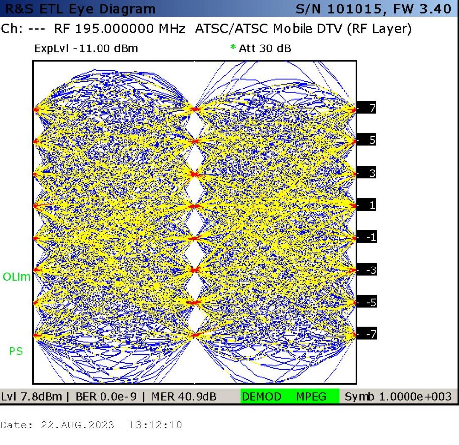
DTV ATSC 1 modulation analysis; 8VSB eye pattern
One thing I will note, TV is acronym-heavy. There are many combinations of letters and abbreviations. I can work on a list of things that I have learned, but one of the most important measurements for the quality of the over-the-air signal is MER, which stands for Modulation Error Ratio. MER is measured in decibels and low MER usually indicates some distortion problem.
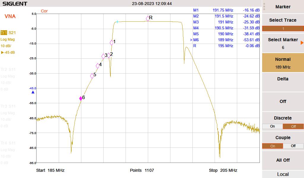
WMEM S21 mask filter sweep
Once the program material hits the exciter, the process is similar but there are a few noted differences. TV transmissions are 6 MHz wide vs. 200 KHz for standard FM. In order to minimize distortion, the signal needs to be precorrected by the exciter for linearity. HD Radio does the same thing to a degree. High-band VHF and UHF stations tend to use slot antennas. These are high-gain broad-banded systems that are generally very simple. The FCC stipulates that spectrum mask filters be used to limit out-of-channel emissions. During the installation process, the filters must be measured and proofed to comply. In addition, the harmonics need to be measured down to -120 dBm because most of them fall in the wireless data and mobile phone spectrum and we know how those folks can be.
Like other segments of the broadcast engineering profession; TV is struggling to find competent technical staff, so if you are willing to learn new things, consider doing some work in television.
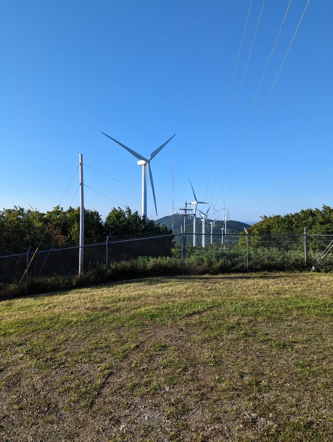
Mars Hill also has many of these giant things:
Wind Turbine, Mars Hill, Maine
I’ve never seen one up close, and I will say they do make a fair bit of noise when it is windy. I also noticed that air density makes a difference in the noise levels. When it is cooler or more humid, the noise level goes up. There are twenty-eight 1.5 MW GE wind turbines that generate enough electricity to power 18,000 average homes annually. Maine has several wind turbine farms in various parts of the state. I believe Mars Hill was the first, completed in 2006.
This is an important question these days. We are running into more situations where timing is important, especially when audio and video codecs are concerned. If there is too much time differential, the codec will unlock. More often, digital transmission methods require precise timing to prevent jitter and dropouts. Some equipment has 10 MHz or 1PPS inputs. Some equipment does not and relies on NTP to keep things in sync.
While searching online for GPS time sever, I came across this post where Austin built a Stratum 1 level time sever with a Raspberry pi and an inexpensive GPS receiver. I thought to myself; damn that sounds interesting. While a Raspberry pi is a hobbyist toy, the same setup can be done with a more serious computer to create a solid NTP server for a facility or LAN.
A little about NTP time servers; Stratum 0 server is directly connected to an atomic clock. Since GPS satellites have atomic clocks, that makes them a Stratum 0 server. Stratum 1 servers are connected to Stratum 0 servers. Stratum 2 servers are connected to Stratum 1 servers and so on. The time accuracy for a Stratum 1 server is 10 microseconds.
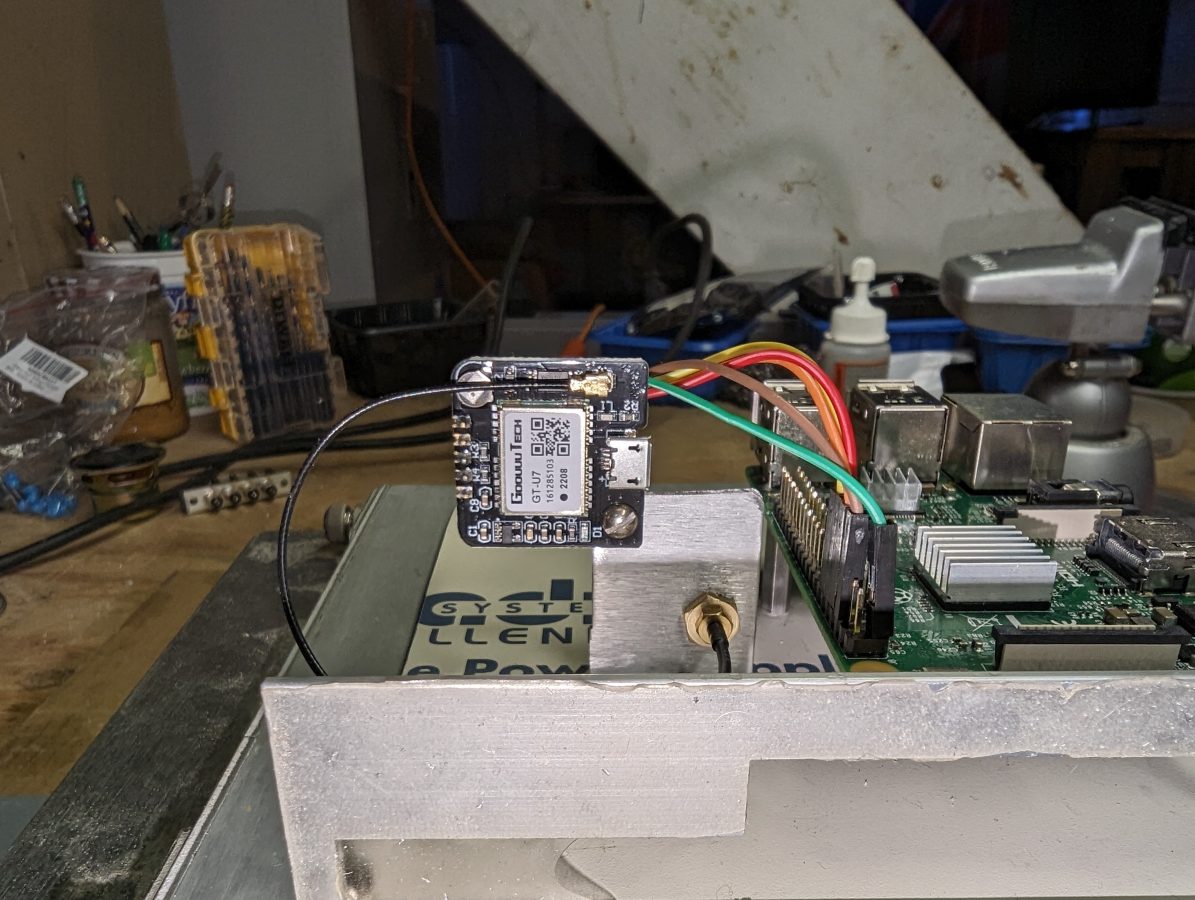
First, I wiped my SD card and loaded a fresh install of Raspberry pi OS. Then followed along with the instructions. For this install, I opted for the cheaper GPS receiver, the GT-U7 (not an affiliate link) from Amazon for $10.99. It comes with a cheap little antenna, which actually worked sitting inside on my desktop while I was configuring the software.
This little module is designed for a drone but works well in this application. The 1PPS output looks clean on the scope. Here is the pinout between the GT-U7 and the Raspberry pi:
GT-U7 pin
pi pin
Use
Color
vcc
1
+3.3 vdc
Green
gnd
6
ground
Brown
txd
8
rxd
Orange
rxd
10
txd
Red
pps
12
GPIO 18
Yellow
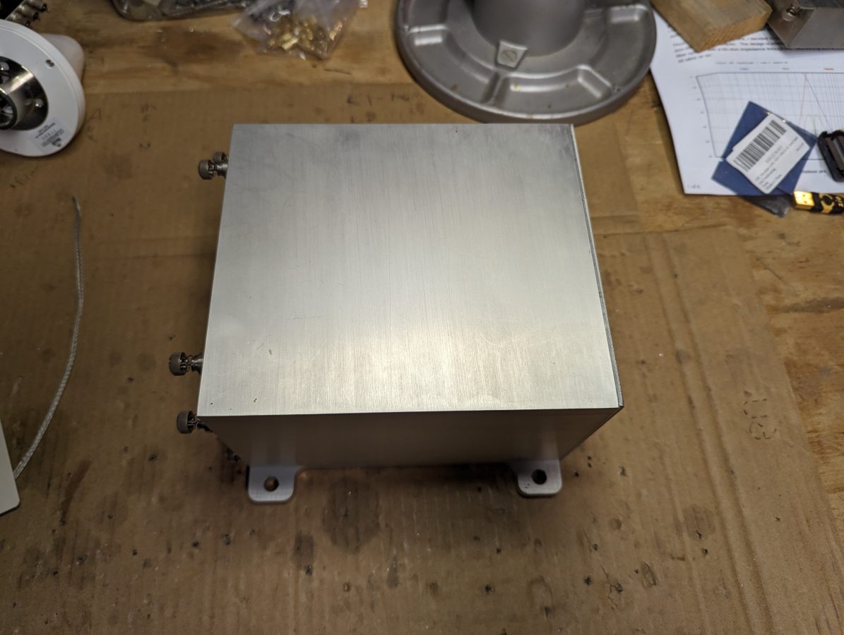
I found this really nice aluminum case in a pile of disused junk at a transmitter site. It used to be for a digital TELCO STL circuit. I figured it would be nice to put the Raspberry pi and GPS receiver in a suitable home.
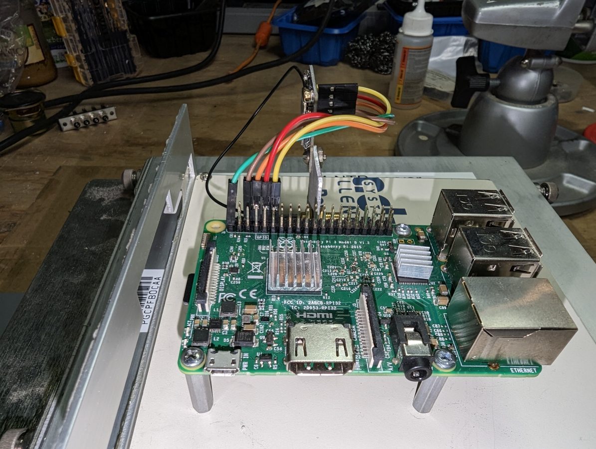
Raspberry pi 3 is mounted on a piece of scrap sheet steel designed to slide into the aluminum case.
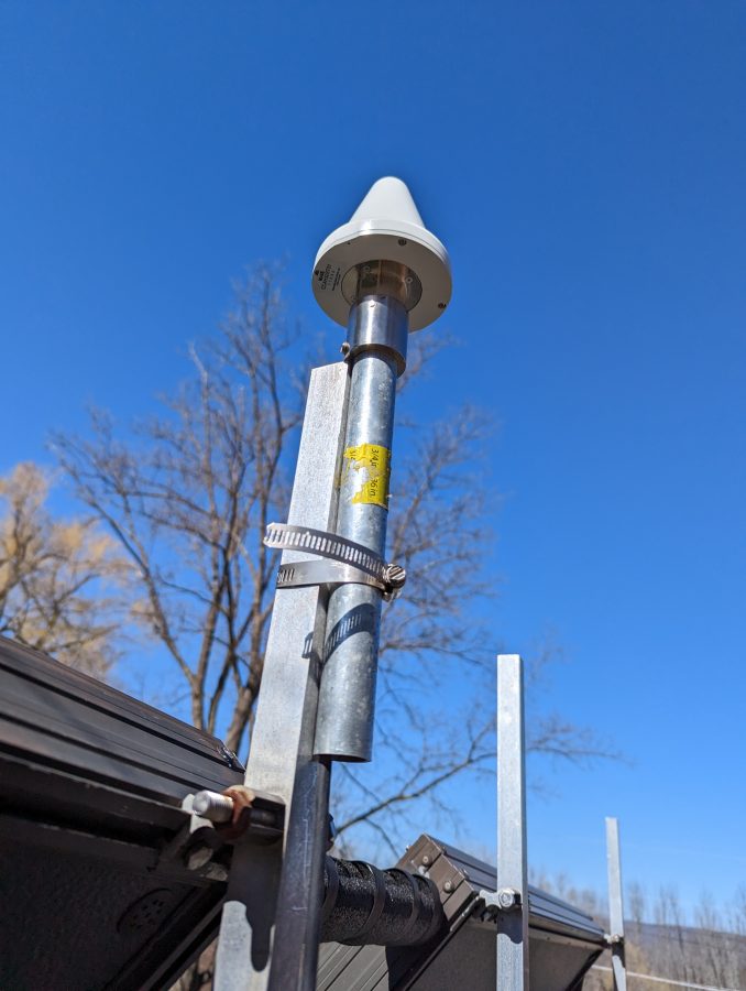
We have several of these nice Panasonic GPS antennas left over from various installs. I pressed one into service on the roof of my house.
Panasonic CCAH32ST01 GPS antenna
I think a high-quality antenna is pretty important to get consistent good performance from this setup. There are three slight problems, however. Unfortunately, this antenna has been discontinued by the manufacturer. Also unfortunate, the GT-7U boards have one of those little IPX RF connectors. Fortunately, I found a short jumper with an F SMA connector. Finally, it requires +5 VDC and the GT-7U runs on 3.3 VDC. The pi does have a 5-volt rail, so I used this 2-way power divider to feed 5 volts to the antenna from one port and the received RF from the antenna goes to the GT-U7 from the other port.
If you are interested, here are the commands to get this thing running:
sudo apt get update
sudo apt get upgrade -y
sudo apt install pps-tools gpsd gpsd-clients chrony
The next step is to make sure the serial port is turned on and enable the ssh login shell since this is going to live in the basement and I don’t want to run down there to fool around with it.
sudo raspi-config
Then go to interface options, serial interface, and enable. The login over the serial interface can be left off. If ssh access is needed, enable ssh, then exit.
Once those packages have been downloaded and installed, some config file editing is needed. You may use whichever method you like, I tend to use nano. First, the /etc/config.txt and add the following to the file:
The uart needs to be enabled if you want to receive NMEA data (NMEA stands for National Marine Electronics Association) It is helpful to see if or how the GPS is working.
Next, the /etc/modules and add:
'pps-gpio'
Reboot, then see if the pps module is working:
lsmod | grep pps
The output should look like this:
Next, there are a few more configuration files that need to be edited.
/ect/default/gpsd – there is a default file that comes with the package, it needs to be modified to start the daemon automatically and look for the pps signal on ttyS0.
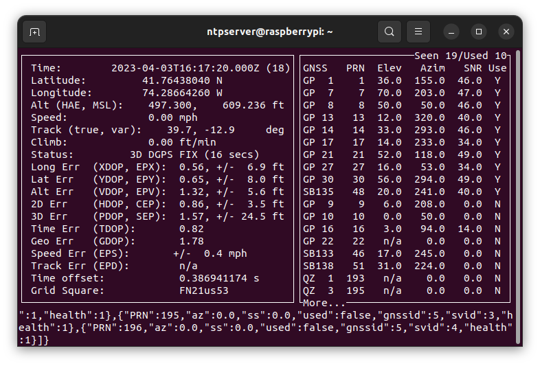
Now check and see if the GPS module is working by typing cgps or gpsmon. The output should look something like this:
It did not take the module too long to find and lock onto GPS. If you don’t see something like this in five minutes or so, go back and check your wiring, and make sure that the data connections are made right. The GT-U7 has a little red LED that is lit when the PPS pulse is not being sent. If this light is not on at all, check your power connection. If it is on steady, check your antenna. If it is flashing, but you are not seeing any output in cgps or gpsmon, check your data connections.
Next and last configuration file is the /etc/chrony/chrony.conf file. At the top of the file, I added the following lines:
#custom lines for PPS
server time-a-g.nist.gov iburst
server time-d-g.nist.gov
server 3.us.pool.ntp.org
server time.windows.com
server time.apple.com
# add refclock pps
refclock SMH 0 delay .1 refid NEMA
refclock PPS /dev/pps0 refid PPS
#my home network
allow 192.168.1.0/24
Leave the rest of the file alone. Basically, the time servers are added to compare the GPS time and act as a backup. The hosts on my home network are allowed to query this host and use it as an NTP server.
Restart Chrony:
sudo systemctl restart chrony
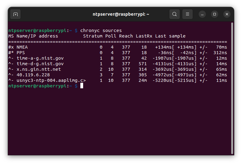
Wait a couple of minutes and check the chrony console to see what is happening: chronyc sources. Should look something like this:
This was after the server had been running for a day. Chrony is great because it measures the hardware performance and creates a delay file. This is used to anticipate any hardware-added delays that the system might have. The last sample column is of interest, the number indicates the offset between the local clock and the source at the last measurement. The far column is the margin of error or greatest variation +/- of the expected values. A value of 0.0000000042 seconds or 0.042 microseconds is pretty good for an $11.00 piece of hardware. Now every host in my house is syncd to satellite within 0.042 microseconds, in lockstep through the time-space continuum.
If I were to do this professionally, I would use better hardware. I think the pi 4 has better serial and ethernet interfaces, more RAM, and a quad-core processor. Last I looked they were $75.00 at Newark.
The GPS module was the cheapest I could find on Amazon. I am slightly concerned about the longevity of this device. Perhaps it will run for a long time, or perhaps not. A quick search brought up several “hats” (plug directly into the 20-pin header). These range in price from about $30.00 to $60.00. What is required of any GPS module is 1PPS output. The configuration would be about the same although some use GPIO 4 instead of 18.