A story about skirted AM towers and Cellular carriers.
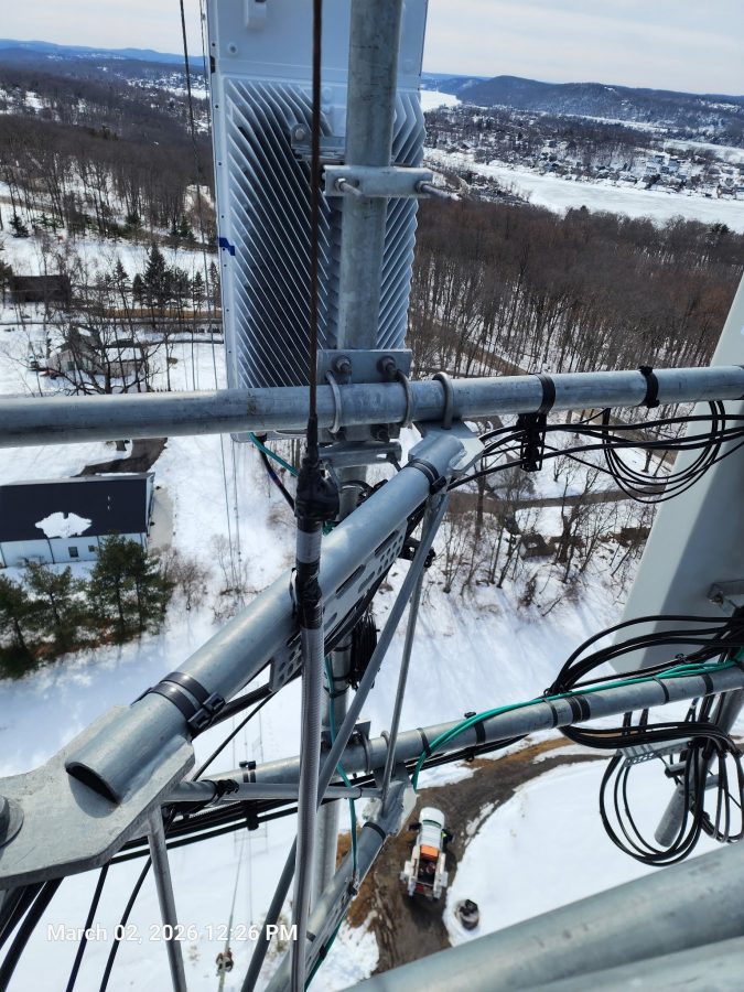
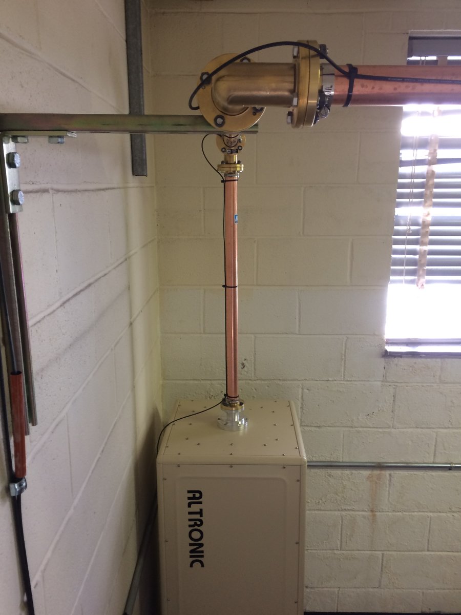
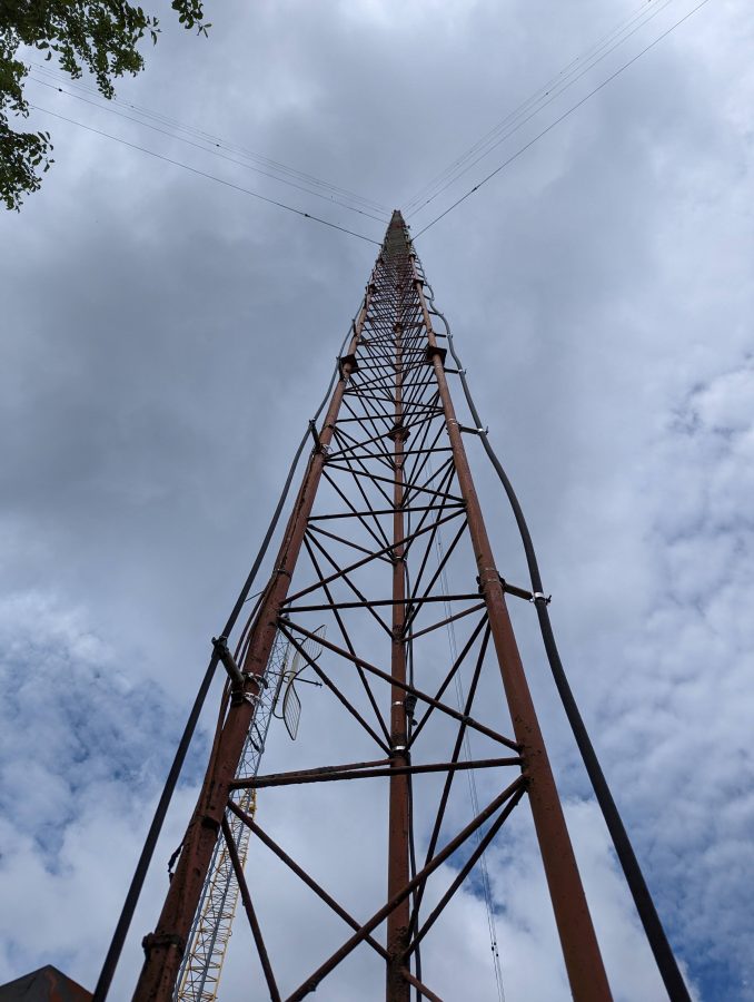
Skirted AM tower with cellular equipment
We take care of a few sites that have skirted AM towers with Cellular equipment installed. For the first few years, all was well. The cell carriers put up their equipment under supervision and we made sure that the AM station’s antenna still was working when the were finished. At some point, things changed.
Stiff arm hitting skirt wire
It is a little bit hard to see because the camera is focused on the foreground and not the background, but the stiff arm from the cell carrier sector is shorting the skirt wire to the tower.
More often then not these days, tower crews show up unannounced and start working on the tower. I had a call from a client their station being off the air only to arrive on site and find a crew on the tower with the AM skirt grounded by a set of battery jumper cables. The ground crew said they kept getting shocked by the wire so they grounded it.
In other cases, they show up, do the work and leave before anybody notices. Then, at some point somebody checks the AM transmitter readings and sees a problem.
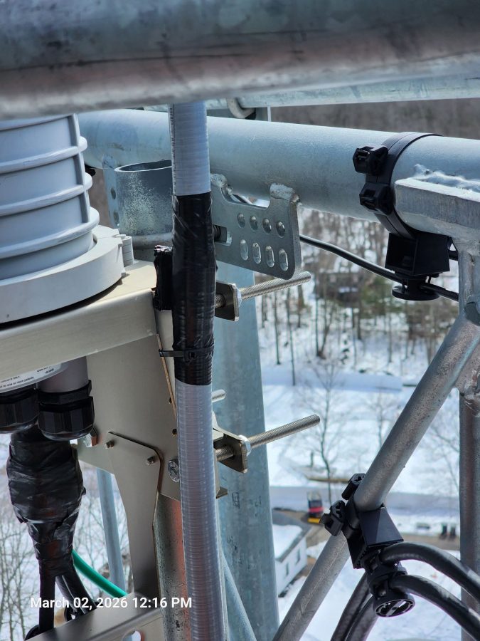
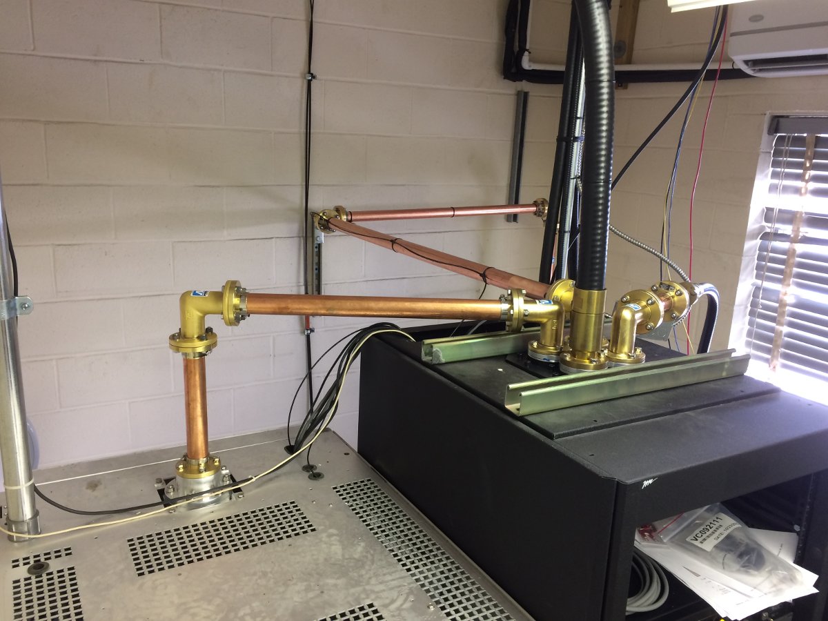
AM skirt wire, shorting against mounting bracket
In another situation, the tower crew came and installed new equipment. They installed an insulating sleeve around the skirt wire (while the transmitter was on) but did not secure it well enough. The eventually, sleeve slipped down the wire and it shorted. No one, not even the tower owner, knew about the tower crew being on the tower.
AM skirt wire insulating sleeve
Same tower, the sleeve on this wire rotated around so that the opening was facing the stiff arm causing a large charred, melted plastic area.
These were repaired with some left over coax-seal and electrical tape. After this, I was able to retune the ATU using my network analyzer.
The only solution, it seems, is to put up more cameras with motion detection notification so when somebody shows up unannounced the station will at least know about it.
I don’t know how many parts there should be in this series, five is a guess.
While some AM stations surrender their licenses to the FCC, others are undergoing needed repair work to stay on the air for a while longer.
WBEC-AM, Pittsfield, MA
WBEC-AM in Pittsfield Mass is the topic of today’s post. This station is Non-Directional day, Directional Night with a two-tower array. This site was built around 1956 when the station moved from Eagle Street, near downtown Pittsfield.
WBEC-FM backup antenna, mounted on WBEC-AM array
This Shively 4-bay antenna is the backup antenna for WBEC-FM. It is being replaced with a 3-bay antenna. The new antenna will serve W277CJ which is relocating from downtown and as a backup for WBEC-FM. A set of signal strength measurements for the nighttime directional array is required along each of the three monitor point radials before and after that work is completed.
The issue these days is the nighttime directional system, which is somewhat erratic when in use. The towers are 180 degrees tall with 35 degrees of top loading making the towers 215 degrees tall or just under 5/8 wavelength. As such both current and voltage are near maximum at the tower base, which makes them very sensitive to any changes at the base.
First, there was an issue with the tower lighting system. It seems that somewhere on the non-reference tower, the beacon conductor is shorted to the tower. When the tower lights are on, the loop current rises and falls in time with the beacon light. Because these are series excited towers, the fuse for the beacon does not blow, but the 60-cycle AC current does show up on the tower loop current reading. Rather than try to repair things on an almost 70-year-old tower light system, it was decided that both towers should get new LED lighting systems.
Next, mice chewed through several AC supply cables for the phasor at the base of tower #1. When switching from day to night patterns, some or all of the contactors would not move or get hung up between states taking the station off the air.
It is unfortunate that the phasor is at the base of one of the towers and the antenna monitor is back inside the building with the transmitter. It takes two people to make adjustments to the nighttime array.
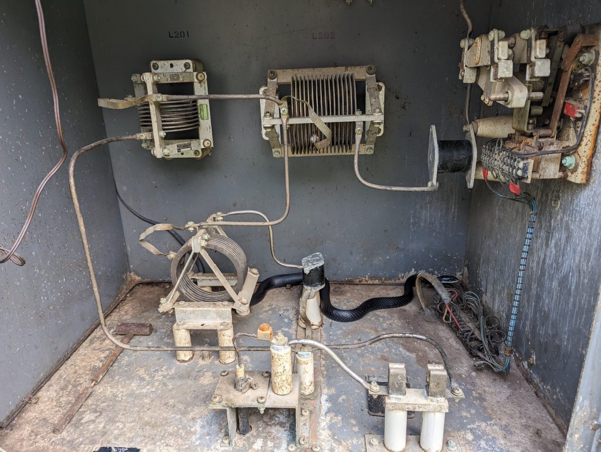
The tower #1 ATU/phasor building is full of old unused equipment, a mouse haven. It also blocks access to several points that need to be sealed up to keep mice from getting in in the first place.
Slatercom LED light system controller
What is interesting is, that the original wiring and photocell failed at some point, and someone simply wired up a new photocell, leaving all of the old equipment in place. Thus, it became difficult to troubleshoot and ID the conductors in use vs the ones abandoned. With the replacement of the tower light systems, I decided that everything must go. The new Slatercom A-1 replacement lighting systems have individual controllers each with its own photocell. In addition, they have wireless links for tower light monitoring. It is great to get rid of the dry pairs going back to the transmitter room, which always creates RF and lightning headaches.
The station will also be saving some money on electricity. The new lighting system draws 88 watts total vs the old incandescent system which drew 1,000 watts with a 50% duty cycle on the beacons. The old system was on all the time due to photocell failure. I estimate they used 17,520 KWh per year on tower lights, at $0.20 per KWh which is $3,504.00 per year vs $308.00 per year for the LED systems. The added benefit of LED fixtures is that they should last much, much longer than incandescent fixtures.
WBEC-FM Harris FM1H3 transmitter scrapped
This lovely Harris FM1H3 was donated to the scrap yard. I believe that this is the second transmitter (1974) for the original 105.3 WBEC-FM which signed on in 1967.
Tower #1 ATU building cleaned out
The building clean-out, unwiring, and rewiring process took about a day and was well spent, in my opinion. Working in a building that is not full of mouse nests, droppings, and stinks like mouse urine is nice. I plugged several holes in the building with stainless steel pot scrubbers and spray foam.
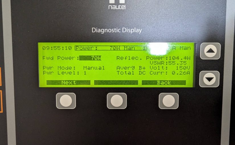
Nautel Amphet 1 transmitter
After removing and replacing the old tower lighting system, the Nautel Amphet 1 transmitter would not run into the nighttime array. This was likely due to the changes at the tower base. I used a VNA to measure each tower’s base impedance which is 42.5 ohms and -j139, 44.5 ohms -j155 respectively.
WBEC Tower #1 base impedanceWBEC Tower #2 Base Impedance
Then the daytime and nighttime common point impedance was measured. Both were off, but the nighttime was more so than the daytime. I adjusted the R and X until both were reasonable and the transmitter would run into both patterns. According to Nautel, the Amphet 1 transmitter runs best into a load of 50 ohms j+5 measured at the transmitter output.
WBEC antenna system schematic
The daytime antenna is non-directional and there is no “common point,” however, there is an R and X adjustment in the phasor for the daytime tower. According to the file I found, it used to be a directional daytime until 1967, when they could make the daytime antenna non-directional. It is an interesting setup.
With the array properly adjusted, readings could be made along the monitor point radials. This station has three monitor points, two are in the nulls and one is in the main lobe. It is the nulls that are the greatest concern. Fortunately, much of the documentation from the original proofs was found in a filing cabinet. While the maps are nice, they date from 1950 and are woefully out of date. However, I was able to find good reference points on the 1950 maps and redraw radials on a Google map.
I found these photos of the monitor points as they were in 1956:
1956 photographs of an engineer making field strength measurements
Those were great because I was able to verify the locations of the monitor points today:
243-degree radial monitor point, 2024
Based on that, I made three maps with radials on the monitor point azimuths:
WBEC-AM Pittsfield, MA 243-degree radial ten measurements
The consulting engineer wanted about 10 readings on each radial. I created an individual map for each radial, marking points where the radial crosses a public road. When it came time to do the monitor points, I loaded the map into my smartphone and followed the directions to each point. It worked very well.
We will return and make post-installation measurements once the new FM antenna is installed.
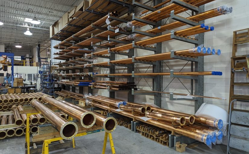
Update: This post is from several years ago (January 31, 2018), however, I did a fairly major revision and added a lot of information, so I am bumping it to the top of the pile. The header picture is from the Myat facility in Mahwah, New Jersey.
Installing transmitters requires a multitude of skills; understanding the electrical code, basic wiring, RF theory, and even aesthetics play some part in a good installation. Working with rigid transmission line is a bit like working with plumbing (and is often called that). Rigid transmission line is often used within the transmitter plant to connect to a four-port coax switch, test load, backup transmitter, and so on. Sometimes it is used outside to go up the tower to the antenna, however, such use has been mostly supplanted by Heliax-type flexible coax.
We completed a moderate upgrade to a station in Albany; installing a coax switch, test load, and backup transmitter. I thought it would be interesting to document the rigid line work required to complete this installation. The TPO at this installation is about 5.5 KW including the HD carriers. The backup transmitter is a Nautel VS-1, analog only.
This site uses a 1 5/8-inch transmission line. That line is good for most FM installations up to about 10-15 Kilowatts TPO. Beyond that, 3-inch line should be used for TPOs up to about 30 Kilowatts. Above 30 KW TPO, 4 inch or greater line is required. There are a few combined FM stations that are pumping 80 or 90 KW up to the antenna. Those require 6 inch or greater line. Even though the transmission lines themselves are rated to handle much more power, reflected power often creates nodes along the line where the forward power and reflected power are in phase. This can create hot spots and if the reflected power gets high enough, flashovers.
This brings up another point; most rigid line comes in 20-foot sections. There are certain FM frequencies that require different lengths due to the aforementioned nodes that fall along the 1 wavelength intervals. If one of those nodes happens on a flange, that could create problems.
Frequencies between 88.1 and 95.9 MHz, use 20-foot line sections
Frequencies between 96.1 and 98.3 MHz, use 19.5-foot line sections
Frequencies between 98.5 and 100.1 MHz, use 19-foot line sections
Frequencies between 100.3 and 107.9 MHz, use 20-foot line sections
TV frequencies are much more complicated. The large channel width and much larger spectrum use means that close attention needs to be paid to line section length. Since low-power TV and translators may need to change frequency, those stations often use Heliax instead of rigid line.
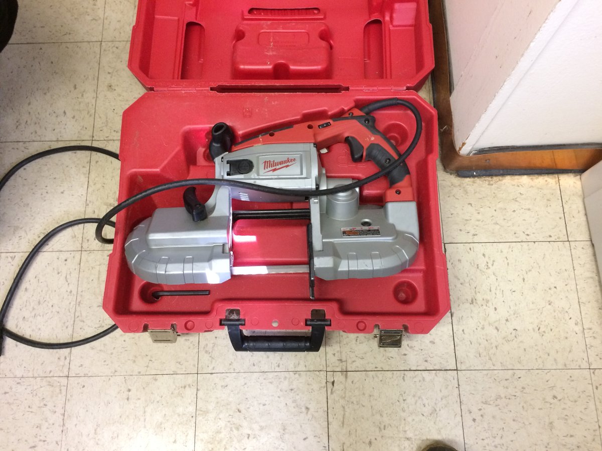
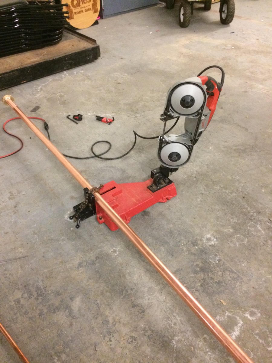
Milwaukee portable band saw
Working with rigid line requires a little bit of patience, careful measurements, and some special tools. Since the line itself is expensive and the transmission line lengthener has yet to be invented, I tend to use the “measure twice and cut once” methodology.
For cutting, I have this nice portable band saw and table. I bought this particular tool several years ago and it has saved me hours if not days of work at various sites. I have used it to cut not just coaxial line and cables, but uni strut, threaded rod, copper pipe, coolant line, conduit, wire trays, etc. If you are doing any type of metalwork that involves cutting, this tool is highly recommended.
Milwaukee 6230N Band Saw with cutting table
There are now Lion battery types of bandsaws which are certainly more portable than this. Still, the table with the chain clamp makes work much easier and the cuts are straight (perpendicular), which in turn makes the entire installation easier.
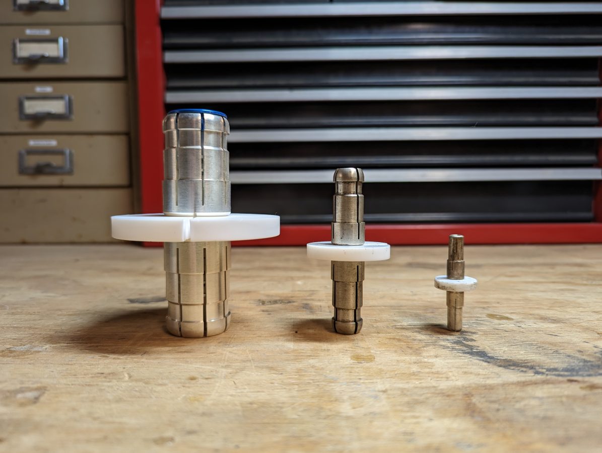
The next point is how long to cut the line pieces and still accommodate field flanges and inter-bay line anchors (AKA bullets).
Inner bay line anchor, aka “bullet” 3 1/8 inch, 1 5/8 inch, and 7/8 inch respectively
The inner conductor is always going to be shorter than the outer conductor by some amount. Below is a chart with the dimensions of various types of rigid coaxial cables.
When working with 1 5/8 inch rigid coax, for example, the outer conductor is cut 0.187 inches (0.47 cm) shorter than the measured distance to accommodate the field flange. The inner conductor is cut 0.438 inches (1.11 cm) shorter (dimension “D” in the above diagram) than the outer conductor to accommodate the inter-bay anchors. These are per side, so the inner conductor will actually be 0.876 inches (2.22 cm) shorter than the outer conductor. Incidentally, I find it is easier to work in metric as it is much easier to measure out 2.22 CM than to try and convert 0.876 inches to some fraction commonly found on a tape measure. For this reason, I always have a metric ruler in my tool kit.
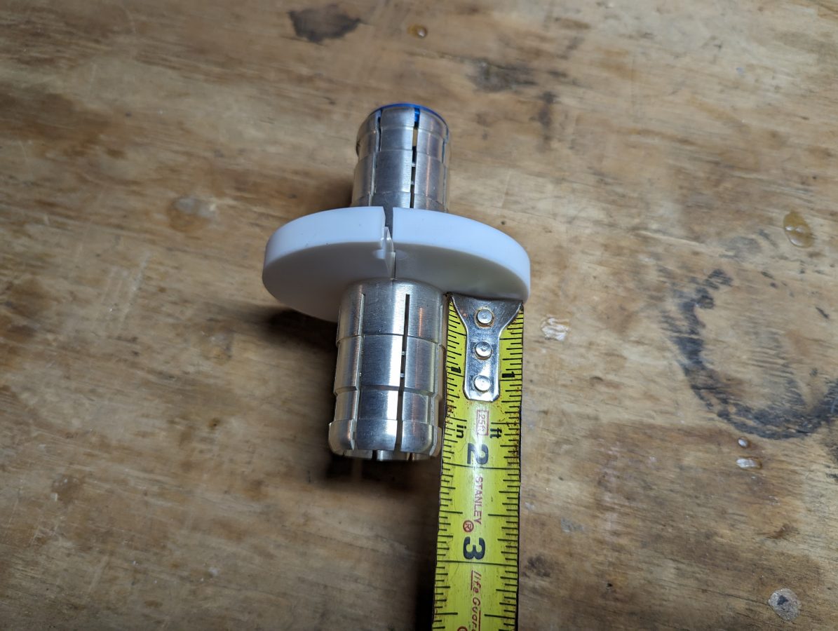
If you do not have a handy chart, you can estimate the inner conductor length by measuring the inner bay anchor from the insulator to the first shoulder. Then multiply by two.
Measuring inner bay line anchor
In this case, the measurement from insulator to shoulder is 11/16th of an inch (17.5 mm). If Clamp On Flange adaptors (AKA field flanges) are being used, don’t forget to account for the small lip (usually less than 1/16th of an inch) around the inside of the flange where the outer conductor is seated. If you are using unflanged couplings instead of field flanges, then you can disregard this.
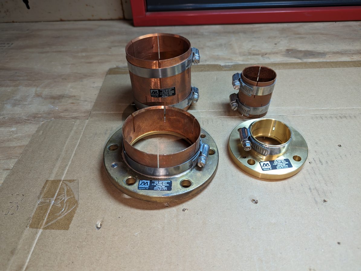
Clamp on Flange adaptors in the front, flangeless couplers in the back1 5/8 inch rigid coax run to Altronic air-cooled 20 KW test load1 5/8 inch rigid coax and 4 port coax switch mounted on top of Middle Atlantic Rack
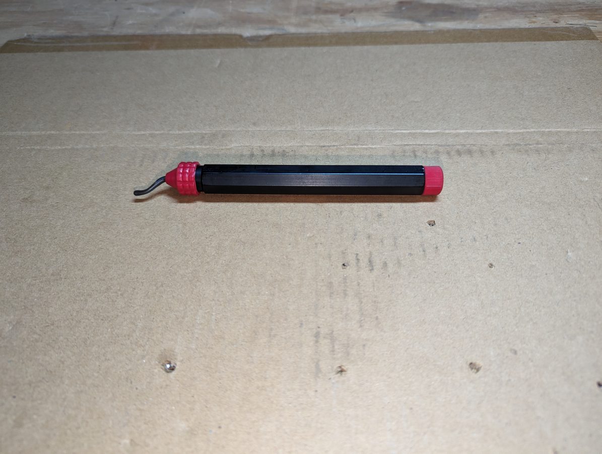
The next step is de-burring. This is really critical at high power levels. I use a copper de-burring tool commonly used by plumbers and electricians.
De-burring tool, can be found in the plumbing isle of most big box hardware stors
One could also use a round or rat tail file to de-bur. The grace of clamp-on field flanges is they have some small amount of play in how far onto the rigid line they are clamped. This can be used to offset any small measurement errors and make the installation look good.
This is the original tower for WKIP, but not the original antenna. It was put up circa 1960 or so and like many towers from that era, has hollow legs. Thus, after 60 years or so, it is deteriorating from the inside out.
WKIP tower #1
This was part of a two-tower directional array. It is odd that a class C station on 1,450 KHz would have a directional antenna at all. Even stranger still, it was directional daytime, non-directional night, both at 1,000 watts. The reason for such an odd situation; the station was co-owned with WGNY in Newburgh and the daytime coverage contours would have overlapped without a directional array. The taller tower is 215 degrees tall with top loading. During the daytime, the pattern goes to the North and it covered very well.
Vertical Bridge, the tower owner, decided it was time to replace the aging structure with a monopole. They are completing the project this summer. Our part is to move WKIP to the shorter tower and put up a temporary FM antenna for the translator. Once the project is completed, WKIP will operate from the shorter tower (which is 85 degrees) permanently, getting rid of the now unnecessary directional antenna on a class C channel. The translator antenna will move back to the monopole, once it is put up.
Problems… Yes, we have a few of those…
WKIP tower #2 with broken guy wire
First, the short tower had a broken guy wire. Actually, the guy wire was fine, but the lowest grip connecting to the equalizing plate was rusted through. It is fortunate that this was discovered because the upper guy wire was getting ready to let go too. Northeast Towers was able to replace all of the grips on that set of guy wires and re-tension the tower. They did a full investigation of all of the other anchors prior to any climbing. This is in a swamp, which has flooded several times over the last few years.
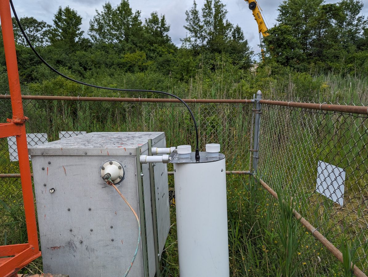
Tower #2, guy wire repaired, Scala FMVMP translator antenna mounted
Next, the temporary FM translator antenna was hung on the tower. It was thought that the 3/8 sample line from the old AM sample system could be used as a temporary transmission line for this system. Unfortunately, that line turned out to be 75-ohm cable TV drop line and was not suitable for transmission of VHF. We had about 600 feet of leftover 3/8 sample line (Cablewave FCC 38-50J) from a decommissioned AM site, so we used that instead. It has quite a bit of loss on VHF, however, for temporary use, it will work.
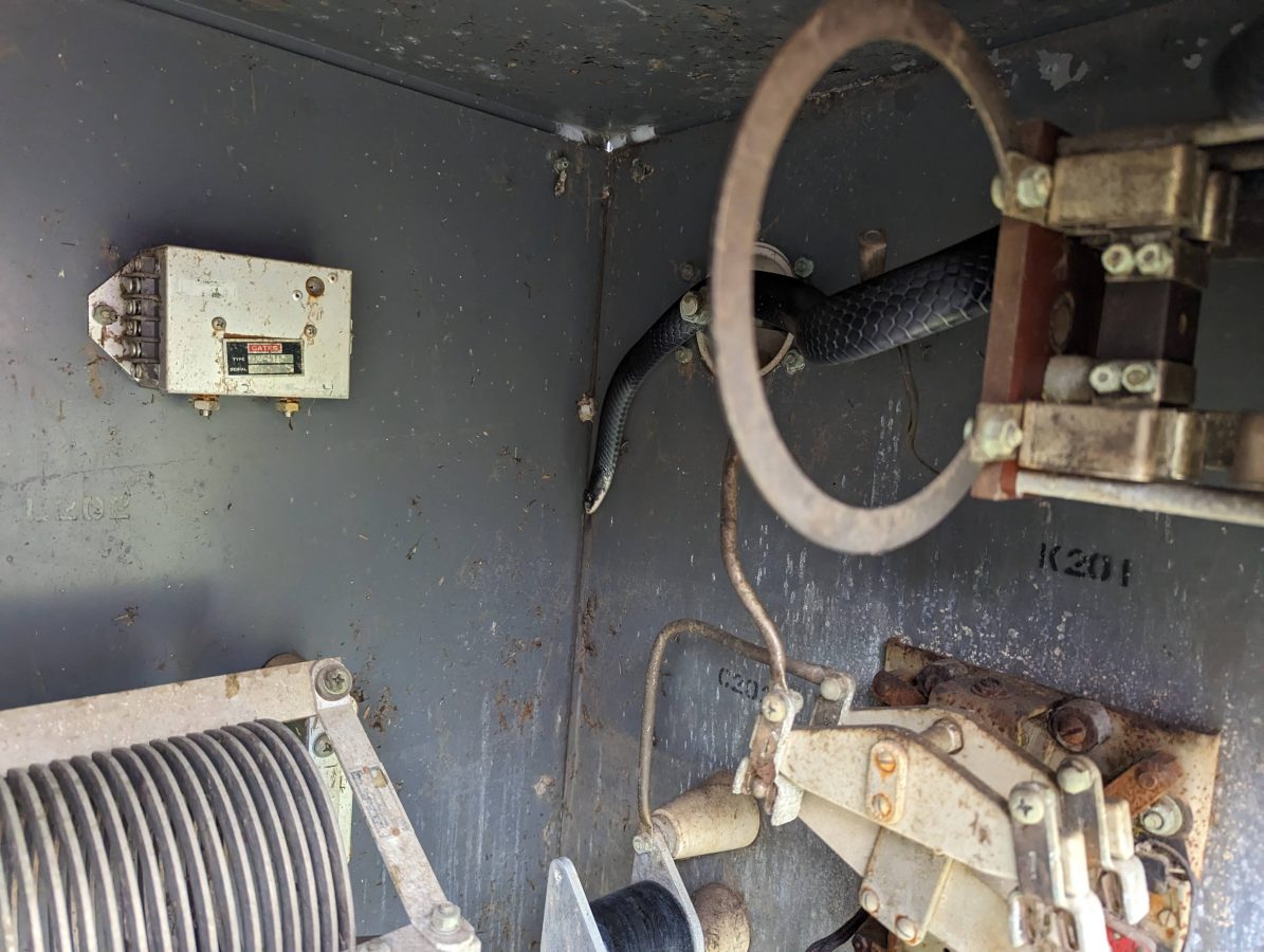
Black Rat Snake, harmless and helpfulBlack Rat Snake
Next, it seems this black rat snake had taken up residence in the ATU cabinet. The bottom of the ATU was full of mouse nests going back many years. One of our employees dutifully cleaned out the mouse nests unknowingly under the watchful eyes of this snake. Only after he was done, did he see the snake coiled up on the disused current meter shunt. There was a mild freakout for several minutes, but the snake left on his own and we got back to work. The black rat snakes are helpful to have around, but perhaps best if he stays outside of the ATU. We will seal up the entryway for the coax, which seems to be where all the critters are coming in.
Kintronic ISO-130-FM-N Isocoil
This Kintronic Isocoil was mounted to the back of the ATU with unistrut. Even though this is a temporary installation, I have found that sometimes temporary things can last much longer than anticipated. Besides, it was easier than trying to use pressure treated 4 x 4 lumber.
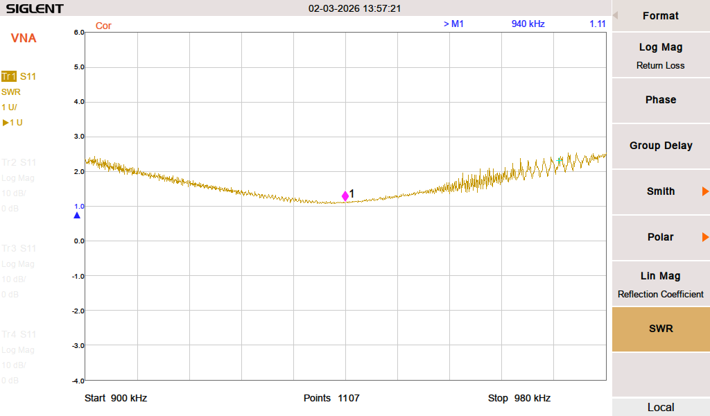
Next, we measured the ATU with the fancy machine (Agilent E5061B network analyzer). In theory, the ATU input should be 50 ohms to match the incoming transmission line. No, instead it was 38 Ohms -j20.
So, a little bit of a retune was required. With the fancy machine, we were able to get it to 52 ohms -j9 or so. This is good enough for now, there will be numerous cranes in the air and the station has an STA to run at 250 watts for the project’s duration. After the new monopole is up, we will measure the base impedance of the tower and tune up the ATU for 50 ohms and then return the station to full power at 1 KW.
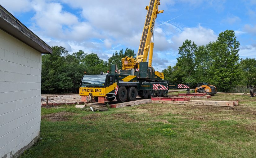
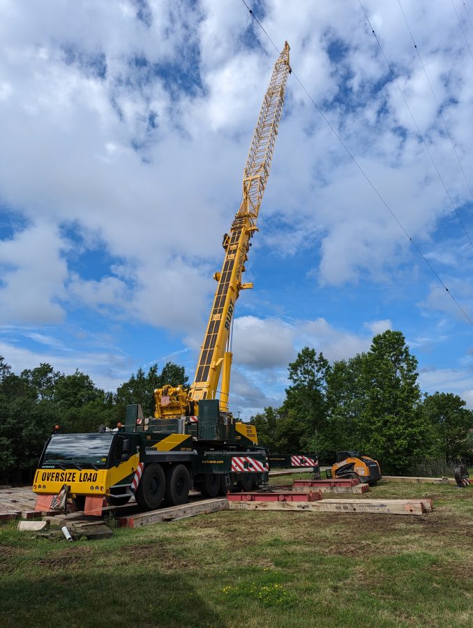
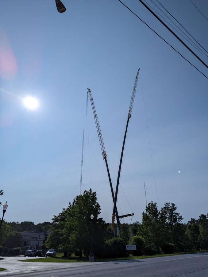
Smaller crane, used to assemble the larger cranes
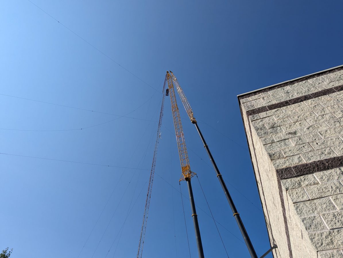
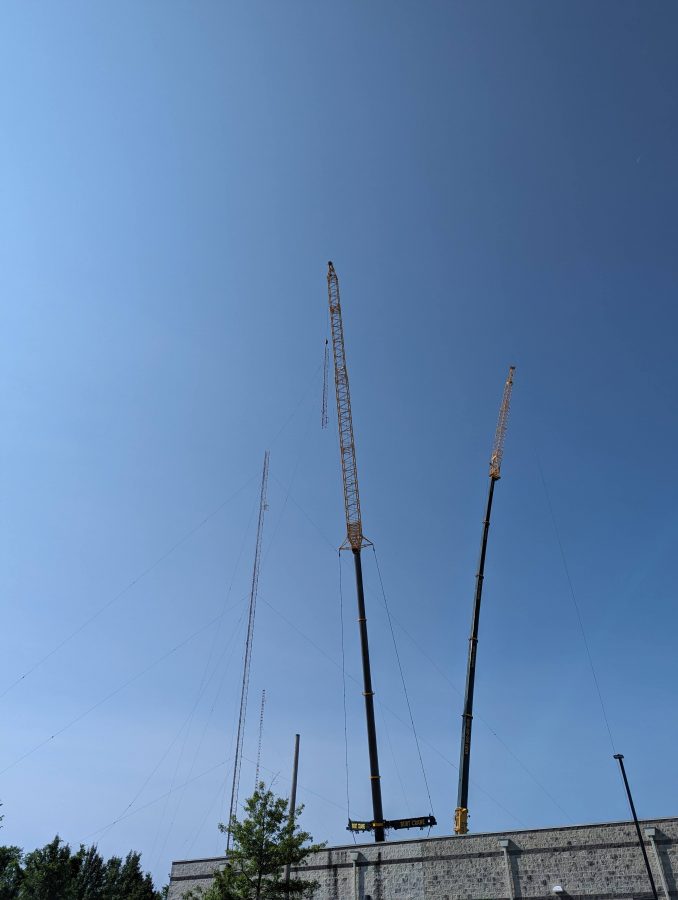
The old tower coming down:
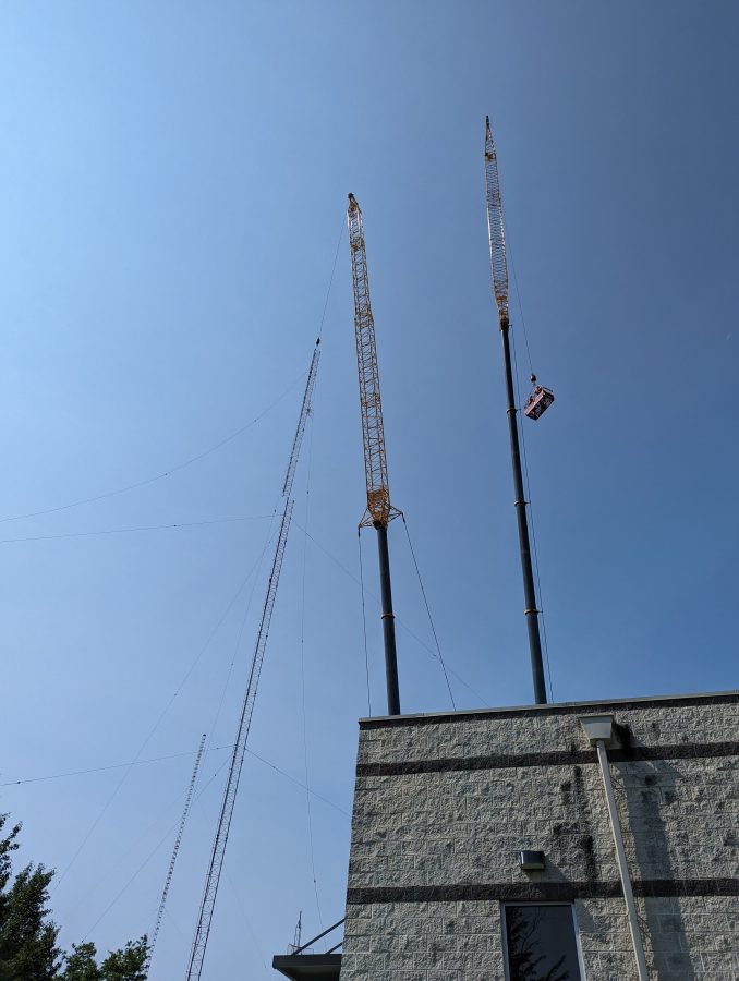
Top section and top loading wires separated
Two cranes were used; one to hold and lower the tower section, the other to lift two tower workers to cut away the sections. The tower was deemed unsafe to climb, therefore it had to be removed like this. It was also unsafe to drop because of the proximity to the studio building and the other tower, which is being retained.
Top section being loweredNext section removed and being loweredNext section removed
You get the idea. These tower sections and guy wires were cut up and put in a scrap metal dumpster. They will be recycled into something else.
Now, they will work on removing the old tower base and putting up the monopole. Once that is done, we will tune up the AM on the short tower and get it back to full power.