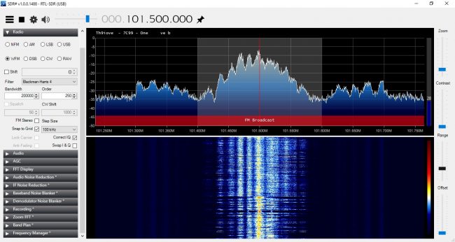
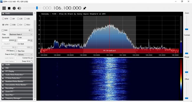
Summer Time Atomspherics; Why is there another FM station on our frequency!!??

That is indeed a good question. There may be several explanations; a pirate, somebody’s Part 15 device, or atmospheric ducting. If the weather is good, tropospheric ducting can cause VHF (FM broadcast) and UHF (TV broadcast as well as Remote Pickup units and STLs) signals to travel far beyond their intended reception areas.

The Troposphere is the zone in the atmosphere closest to the Earth, ranging from 0 to 15 km. It is the area where most weather phenomena take place. For VHF and sometimes UHF, refraction can bend the signal back towards the surface of the Earth. Refraction at lower altitudes (called surface ducts) can cause radio signals to travel shorter distances than normal unless they are over water. Refraction at higher altitudes (elevated ducts) can cause those same signals to travel far beyond their normal range, sometimes hundreds or thousands of kilometers.

Three things affect the tropospheric refraction index (or N); water vapor, air pressure, and air density. At higher altitudes, the air is normally cooler, less dense, and dryer than air closer to ground level. However, high barometric pressure will often bring warm, dense, moist air to high altitudes. This can create a layer of warm air over a layer of cooler air known as a temperature inversion. This can create a “duct” in the upper troposphere similar to a waveguide. These signals can be very strong, sometimes overpowering a local FM signal due to the capture effect.

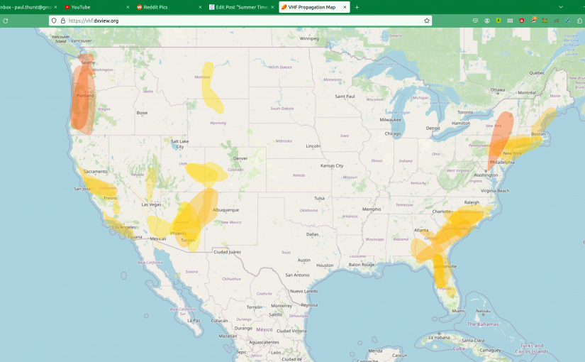
There is an online source that predicts atmospheric ducting, mostly used by Amateur Radio operators, but it can also be a useful troubleshooting tool: https://vhf.dxview.org/

That site produces a map like this:
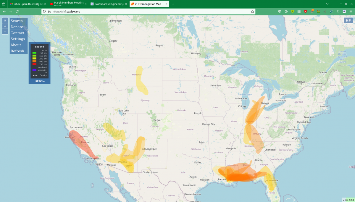
VHF Ducting map

This can happen any time of the year but is more common in summertime. Tropospheric ducting is not an effect of ionization from the sun. This phenomenon is known as Sporadic E, which will be covered below.

The good news is tropospheric ducts normally last a few minutes to a few hours. Sometimes they can last longer however changes in the width or length of the ducts will change the frequencies and distances that RF signals travel along that duct. In addition, if you are hearing a co-channel FM station from many hundred kilometers away, listeners of that station are now hearing your station the same way.

Another long-distance VHF propagation phenomenon is called Sporadic E layer propagation or simply Sporadic E. This happens when the Ionosphere is heavily affected by a solar storm or sunspot. Sunspots run in an 11-year cycle. We are approaching the solar maximum for Solar Cycle 25, predicted to happen in July 2025.
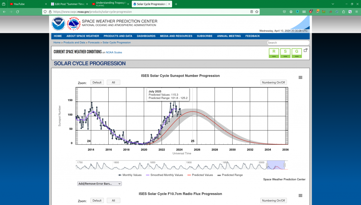
NOAA Space Weather Solar Cycle 25 progression

Sporadic E is much less predictable, more random, and short-lived. Solar storms can create highly ionized areas in the E layer of the Ionosphere, creating skywave conditions for VHF signals. These signals will skip in the same way that HF and MF signals do. Fortunately, these conditions usually last a few seconds or minutes at most. More on the solar cycle can be found here: https://www.swpc.noaa.gov/products/solar-cycle-progression
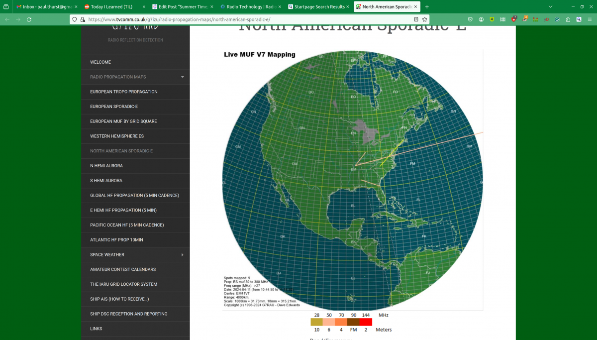
North American Sporadic E Map

Once again, Amateur Radio operators are interested in this as a mode of communication. There is a Sporadic E map online at: https://www.tvcomm.co.uk/g7izu/radio-propagation-maps/north-american-sporadic-e/

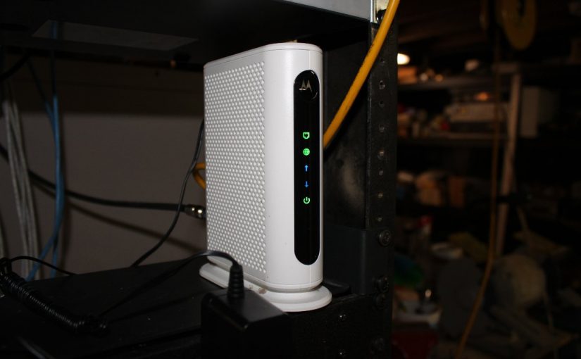
DOCSIS 3 Cable Modems

The internet is relied upon for many different functions. One thing that I see more of is STL via the public network. There are many ways to accomplish this using Comrex Bric links, Barix units, or simply a streaming computer.

We often can take for granted the infrastructure that keeps our connection to the public network running. Cable modems are very common as either primary or backup devices at transmitter sites, homes, offices, etc. The basic cable modem uses some type of DOCSIS (Data Over Cable Service Interface Specification) modulation scheme. This system breaks up the bandwidth on the coaxial cable into 6 MHz channels for downstream and upstream transmission. Generally, downstream transmission is 16 channels of 256-QAM signals. Upstream is 4 channels of QPSK or up to 64-QAM signals. Depending on your traffic shaping plan with the cable company, this will allow up to 608 Mbps down and 108 Mbps up. Those speeds also can change due to network congestion, which is the bane of coaxial cable-based internet service.

The internet should now be considered a public utility. Especially after the COVID-19 emergency, distance learning, telecommuting at all the other changes we are experiencing. I know in the past, ISPs were reluctant to accept that role, as there are many responsibilities. That being said, when the public network goes down, many things grind to a halt.

Sometimes the problem is at the cable office or further upstream. Loss of a backbone switch, trunk fiber, or DOCSIS equipment will cause widespread outages which are beyond anything a field engineer can deal with.

Then there are the times when it is still working, but not working right. In that situation, there are several possible issues that could be creating a problem. A little information can go a long way to returning to normal operation. One thing that can be done with most newer cable modems, log into the modem itself and look at the signal strength on the downstream channels. Again, most cable modems will use 192.168.100.1 as their management IP address. The username and password should be on the bottom of the modem. I also Googled my modem manufacturer and model number and found mine that way.

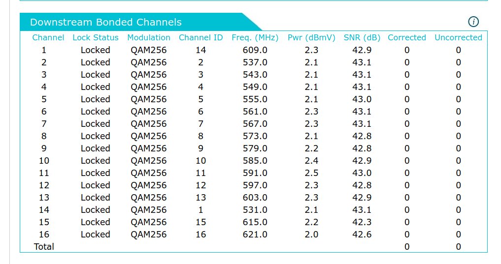
Navigate around until you find a screen that looks like this:

DOCSIS 3.0 Downstream Channel Statistics

There is a lot of helpful information to look at. The first thing is the Pwr (dBmV) level. DOCSIS 3 modems are looking for -7 dBmV to +7 dBmV as the recommended signal level. They can deal with -8 to -10 dBmV / +8 to +10 dBmV as acceptable. -11 to -15 dBmV / +11 to + 15 dBmV is maximum and greater than -15/+15 dBmV is out of tolerance.

The next column to look at is the SNR (Signal to Noise Ratio). DOCSIS 3 needs to be greater than 30 dB and preferably 33 dB or greater.

The last two columns are the codeword errors. This is a Forward Error Correction (FEC) system that verifies the received data and attempts to correct any corrupted bits. The lower the codeword error number, the better the data throughput. Codeword errors are often due to RF impairments and can be a strong indicator of cable or connector issues. Another possible cause is improper signal strength, which can be either too high or too low.

Upstream data is transmitted on 4 channels.

DOSSIS 3.0 Upstream Channels

The only statistic that is useful on the upstream channels is the Pwr, which should be between 40 and 50 dBmV.

I have found a few simple parts and tools that can sometimes restore a faltering cable connection. First, I have several attenuator pads; 3dB, 6dB and 10 dB with type F connectors. This has actually cured an issue where the downstream signal was too hot causing codeword errors. Next, some good Ideal weatherproof crimp-on F connectors for RG-6 coax and a good tool should also be in the tool kit. I have had to replace mouse-chewed RG-6 from the outside cable drop into the transmitter building. Fortunately, there was some spare RG-6 in the transmitter room.

If these attempts do not fix the issue, then of course, be prepared to waste a day waiting for the cable company to show up.

Part 101, Private Fixed Microwave Service

I have been tasked with installing one of these systems for a sixteen-channel bi-directional STL.  This system was first mentioned here: The 16 channel bi-directional STL system.  As some of you pointed out, the unlicensed 5.8 GHz IP WLAN extension was the weak link in this system.  It was not an interference issue, however, which was creating the problems.  The problem was with layer two transparency in the TCP/IP stack.  Something about those Cambium PTP-250s that the Wheatstone Blade hardware did not like and that created all sorts of noise issues in the audio.   We installed the Wheatstone Edge Routers, which took care of the noise issue at the cost of latency.  It was decided to go ahead and install a licensed link instead of the license-free stuff as a permanent solution.

Thus, a Cambium PTP-820S point-to-point microwave system was purchased and licensed.  The coordination and licensing took about three months to complete.  We also had to make several changes to our network architecture to accommodate the new system.  The PTP-820 series has a mast-mounted radio head, which is the same as the PTP-250 gear.  However, for the new system, we used three different ports on the radio to interface with our other equipment instead of the single port PTP-250 system.  The first is the power port, which takes 48 VDC via a separate power cable instead of POE.  Then there is the traffic port, which uses Multi-Mode fiber.  Finally, there is the management port, which is 1GB Ethernet and the only way to get into the web interface.  The traffic port creates a completely transparent Ethernet bridge, thus eliminating all of the layer two problems previously encountered.  We needed to install fiber transceivers in the Cisco 2900 series switches and get those turned up by the IT wizards in the corporate IT department.

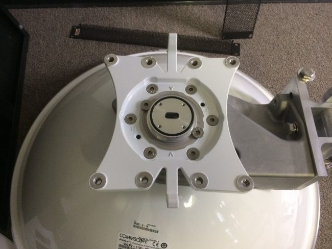
Andrew VLHP-2-11W 11 GHz microwave antenna
Andrew VHLP-2-11W 11 GHz microwave antenna

The radios mount directly to the back of the 24-inch 11 GHz Andrew antenna (VHLP2-11) with a UBR100 interface.  The waveguide from the radios is a little bit deceptive looking, but I tried not to overthink this too much.  I was careful to use the O ring grease and conductive paste exactly where and when specified.  In the end, it all seemed to be right.

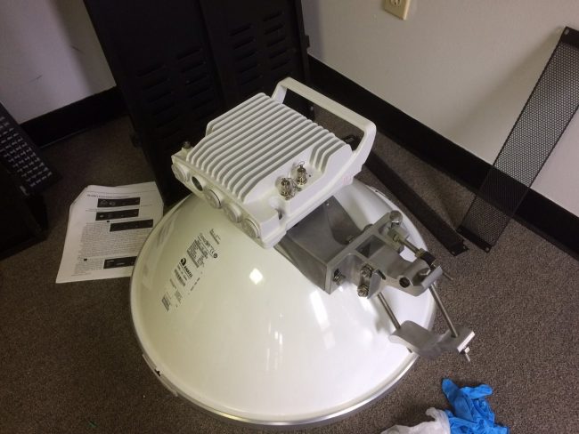
Cambium PTP-820S mounted on antenna
Cambium PTP-820S mounted on Andrew antenna

Not wanting to waste time and money, I decided to do a back-to-back test in the conference room to make sure everything worked right and I had adequately familiarized myself with the ins and outs of the web interface on the Cambium PTP-820 radios.  Once that was done, it was time to call the tower company.

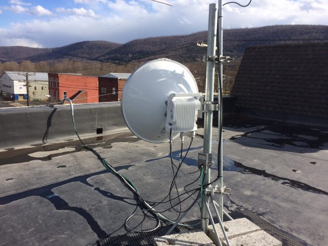
Cambium PTP-820S on studio roof

One side of these is mounted on the studio building roof, which is a leased space.  I posted RF warning signs around the antennas because the system ERP is 57.7 dBm, which translates to 590 watts at 11 GHz.  I don’t want to fry anybody’s insides, that would be bad.  The rooftop installation involved pulling the MM fiber and power cable through a 1 1/4-inch EMT conduit to the roof.  Some running back and forth, but not terrible work.  I used the existing Ethernet cable for the management port.  This will be left disconnected from the switch most of the time.

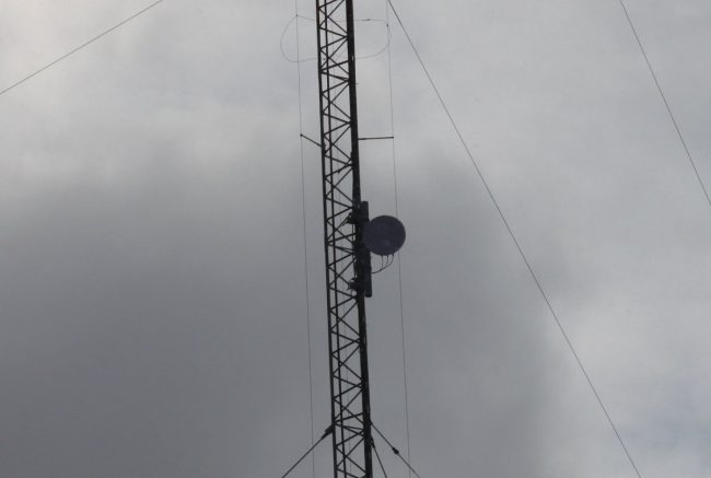
Cambium PTP-280S 11 GHz licensed microwave mounted on a skirted AM tower

The other side is mounted at about 85 feet AGL on a hot AM tower.  I like the use of fiber here, even though the tower is skirted, the AM station runs 5,000 watts during the daytime.  We made sure the power cables and Ethernet cables had lighting protectors at the top of the run near the dish and at the bottom of the tower as well as in the transmitter room rack.  I know this tower gets struck by lightning often as it is the highest point around for miles.

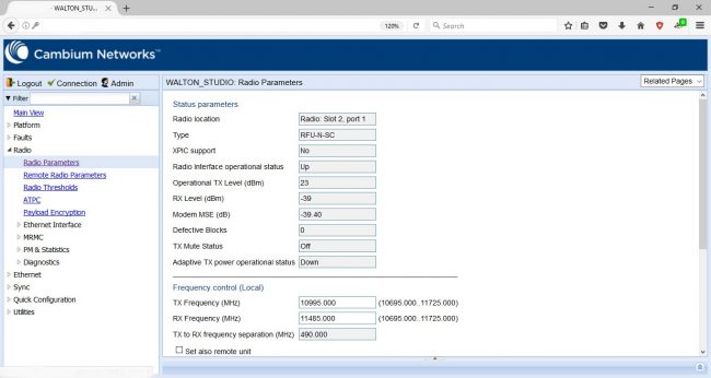
PTP-820S RSL during aiming process
PTP-820S RSL during the aiming process

Aligning the two dishes was a degree of difficulty greater than the 5.8 GHz units.  The path tolerances are very tight, so the dishes on each end needed to be adjusted in small increments until the best signal level was achieved.  The tower crew was experienced with this and they started by panning the dish to the side until the first side lobe was found.  This ensured that the dish was on the main lobe and we were not chasing our tails.  In the end, we achieved a -38 dBm RSL, the path predicted RSL was -36 dBm so close enough.  This means the system has a 25 dB fade margin, which should be more than adequate.  While were aligning the transmitter site dish, a brief snow squall blew through causing a whiteout and the signal to drop by about 2 dB.  It was kind of cool seeing this happen in real-time, however, strangely enough, the tower crew was not impressed by this at all.  Odd fellows, those are.

Currently brushing up on FCC part 101 rules, part C and H.  It is always good to know the regulatory requirements of any system I am responsible for.  As AOIP equipment becomes more mainstream, I see many of these types of installations happening for various clients.

The Realtek 2832U

In my spare time (lol!) I have been fooling around with one of those RTL 2832U dongles and a bit of software.  For those that don’t know, the RTL 2832U is a COFDM demodulator chip designed to work with a USB dongle.  When coupled with an R 820T tuner a broadband RF receiver is created  There are many very inexpensive versions of these devices available on Amazon, eBay, and other such places. The beauty of these things is that for around $12-30 and a bit of free software, one can have a very versatile 10 KHz to 1.7 GHz receiver.  There are several good software packages for Windoze, Linux, and OSX.

The one I recommend for beginners is called SDR-Sharp or SDR#.  It has a very easy learning curve and there is a lot of documentation available online.  There are also several worthwhile plugins for scanning, trunking, decoding, etc.  At a minimum, the SDR software should have a spectrum analyzer, waterfall display, and the ability to record audio and baseband PCM from the IF stage of the radio.

Some fun things to do; look at the output of my reverse registering smart (electric) meter (or my neighbor’s meter), ACARS data for the various aircraft flying overhead, a few trips through the EZPass toll lanes, some poking around on the VHF hi-band, etc.  I also began to think of Broadcast Engineering applications and a surprising number of things came to mind:

  • Using the scanner to look for open 950 MHz STL frequencies
  • Inexpensive portable FM receiver with RDS output for radio stations
  • Inexpensive Radio Direction Finder with a directional antenna
  • Inexpensive Satellite Aiming tool

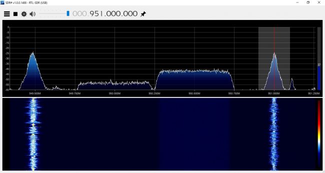
Using SDR sharp and a NooElec NESDR Mini+ dongle, I made several scans of the 945-952 STL band in a few of our markets.  Using the scanner and frequency search plugin, the SDR software very quickly identified all of the in-use frequencies.  One can also look at the frequency span in the spectrum analyzer, but this takes a lot of processing power.  The scanner plugin makes this easier and can be automated.

950 MHz STL frequencies, Albany, NY
Analog and digital 950 MHz STL frequencies, Albany, NY

I also listened to the analog STLs in FM Wideband mode.  Several stations are injecting their RDS data at the studio.  There is one that appears to be -1500 Hz off frequency.  I’ll let them know.

Next, I have found it beneficial just to keep the dongle and a small antenna in my laptop bag.  Setting up a new RDS subcarrier; with the dongle and SDR# one can quickly and easily check for errors.  Tracking down one of those nasty pirates; a laptop with a directional antenna will make quick work.

Something that I found interesting is the waterfall display for the PPM-encoded stations:

WPDH using RTL 2832U and SDR Sharp

Not only can you see the watermarking on the main channel, you can also see the HD Radio carriers +/- 200 KHz from the carrier frequency.  That is pretty much twice the bandwidth allotment for an FM station.

WDPA using RTL 2831U with SDR Sharp
WDPA using RTL 2831U and  SDR Sharp

Those two stations are simulcasting.  WPDA is not using Nielson PPM nor HD Radio technology.  There is all sorts of interesting information that can be gleaned from one of these units.

Aiming a satellite dish at AMC-8 can be a bit challenging.  That part of the sky is pretty crowded, as it turns out.  Dish pointer is a good general reference (www.dishpointer.com) and the Dish Align app for iOS works well.  But for peaking a dish, the RTL 2832 dongle makes it easy to find the correct satellite and optimize the transponder polarization.  Each satellite has Horizontal and Vertical beacons.  These vary slightly in frequency, thus, but by tuning to the correct beacon frequency, you can be assured that you are on the right satellite.  All of the radio network programming on AMC-8 is on vertically polarized transponders, therefore,  the vertical beacons are of interest.  Here are the vertical beacons for satellites in that part of the sky:

Satellite Position C band Vertical beacon (MHz) L band (LNB) Vertical beacon (MHz) Comment
AMC-8 139W 4199.5 949.25
AMC-7 137W 3700.5 1450.25
GOES15 135.4W 2209.086 N/A NOAA WX
AMC-10 135W 4199.5 949.25
Galaxy 15 133W 4198 949.00
AMC-11 131W 4199.5 949.25
Galaxy 12 129W 3700.5 1450.25

For those in the continental United States, there is not much else past 139W, so AMC-8 will be the westernmost satellite your dish can see.  Of course, this can be used in other parts of the world as well, with the correct information. Bringing a laptop or Windows tablet to the satellite dish might be easier than trying to drag a XDS satellite receiver out.

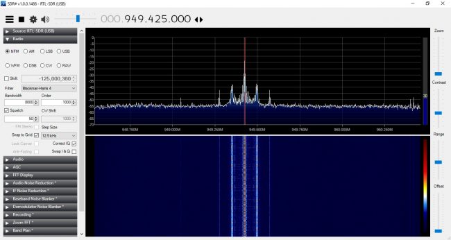
AMC8 vertical beacon output from LNB

In order to use the RTL-2832U, simply split the output of a powered LNB, and install a 20-30 dB pad in between the splitter and the dongle.  Using the vertical beacon on 949.25 MHz, adjust for maximum signal.

For some other uses; look for the nearest and best NOAA Weather radio station.  Several times the local NOAA weather station has been off the air for an extended period of time.  Sometimes, another station can be found in the same forecast area.  Heck, couple these things to a Raspberry Pi or Beaglebone black, and a really nifty EAS receiver is created for NOAA and broadcast FM.  One that perhaps, can issue an alarm if the RSL drops below a certain threshold.

I am sure there are plenty of other uses that I am not thinking of right now…