History is one of my interests. Working in Radio over the years, there is plenty of interesting history that surrounds the first electronic mass media. My parents grew up in the depression/WWII era. For them, radio was a vital information source. Listening to FDR’s fireside chats about the economy and the progress toward recovery was a friendly voice reassuring them that times were indeed difficult but they would get better. Then the shock of the Pearl Harbor attack on December 7th rippled through the airwaves on a Sunday afternoon. These are the life long memories of my mother, who is now 92.
Preserving some of this history for following generations, who take the free flow of information for granted, is a worthwhile cause. Thus, I want to visit, then write about the many Radio Museums around the country. Each is a little bit different with its collection and interpretation of radio history.
Over the Christmas/New Years holidays, my SO and I went on a road trip around Western North Carolina and Virginia. We visited the Asheville Radio Museum along the way.
One thing that I found interesting is the People’s Radio. This was from Nazi era Germany (1933-45).
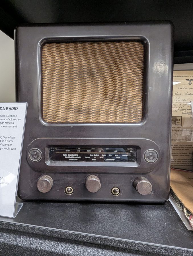
This radio only had medium wave and was designed only to receive radio stations from Nazi radio stations. In order to possess a radio, a permit from the government was needed.
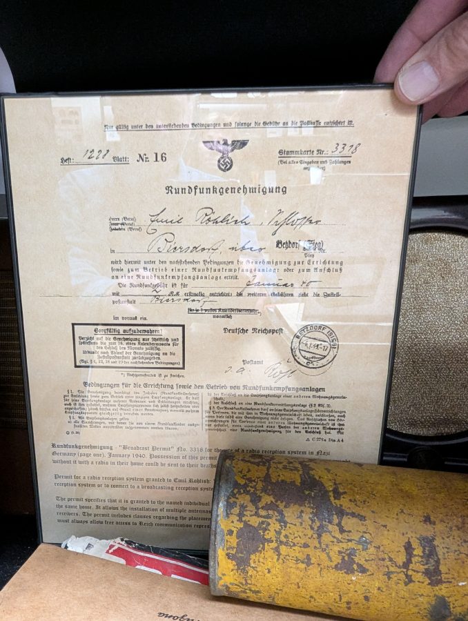
Having a radio receiver without a permit would lead to an arrest and possibly being sentenced to death. In addition to that, getting caught listening to a non-Nazi radio station would result in arrest, imprisonment and later in the war, possibly death. It was no trivial matter.
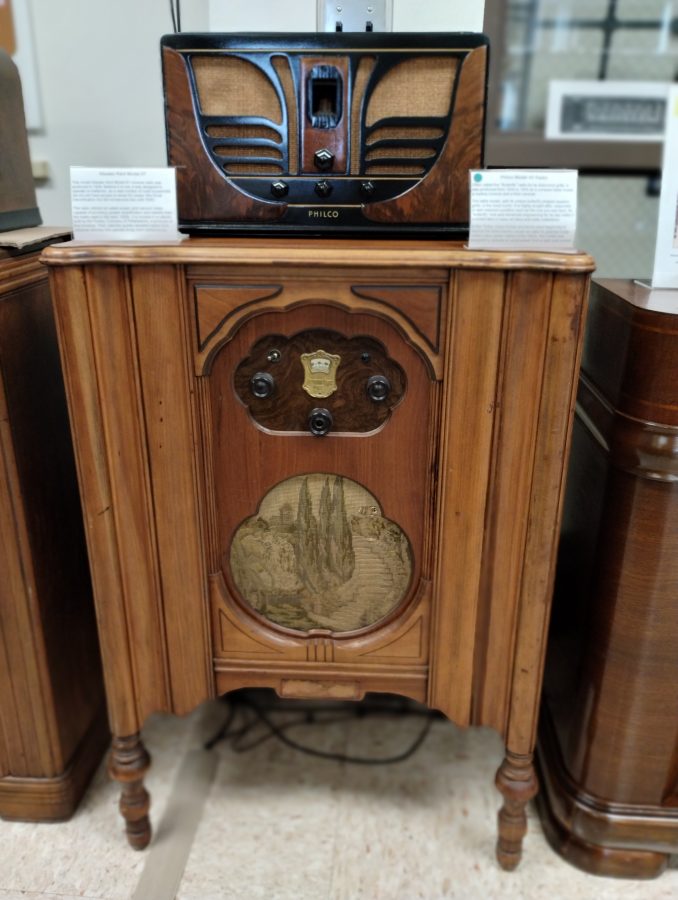
Older radios were often treated as a piece of furniture. My parents both said that evenings were often spent sitting in the living room listening to the radio. Radio dramas were performed live and included programs like Amos ‘n’ Andy, Mercury Theater of the Air, Jack Benny, Ed Sullivan, The Lone Ranger, The Fleischmann’s Yeast Hour, Calling all Cars, The Answer Man, Dick Tracy, Death Valley Days, The National Barn Dance, to name a few.
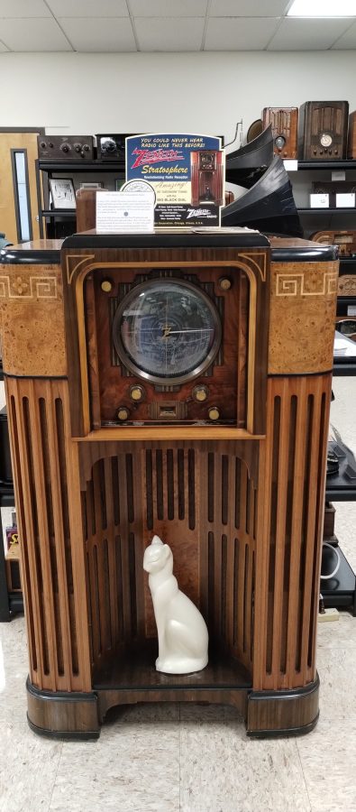
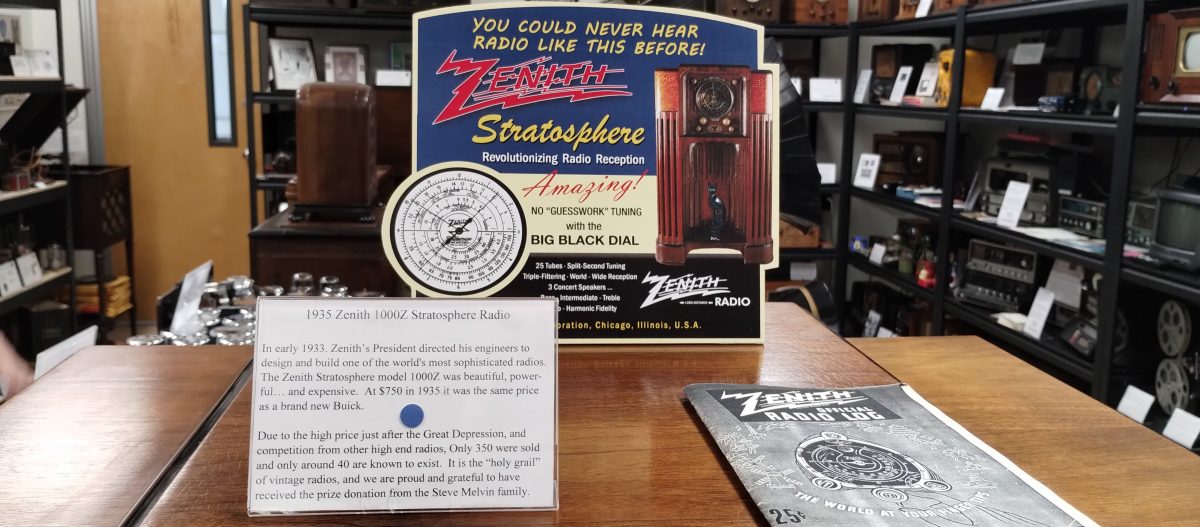
The top of the line console radio was the Zenith Stratosphere 1000Z. The porcelain cat was a notable feature for these radios.
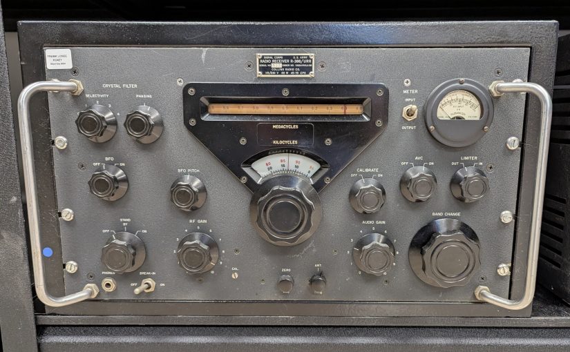
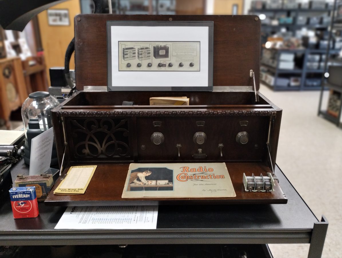
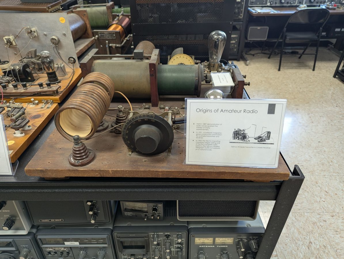
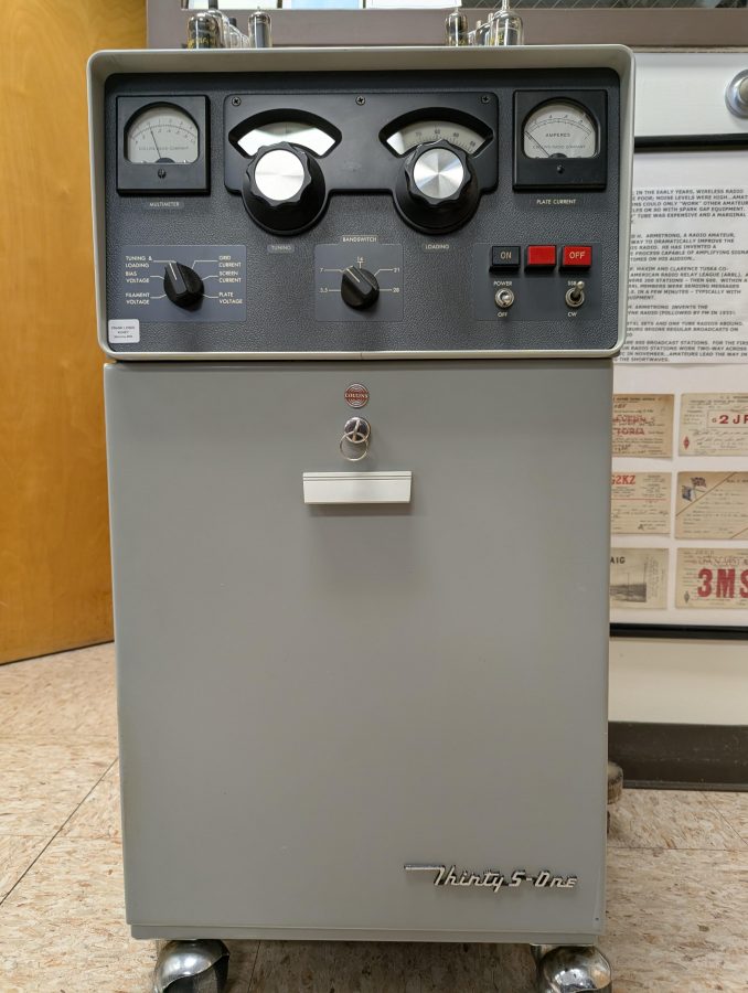
The Asheville Radio Museum holds Amateur radio license W4AFM. They have a decent display of vintage Amateur radio gear.
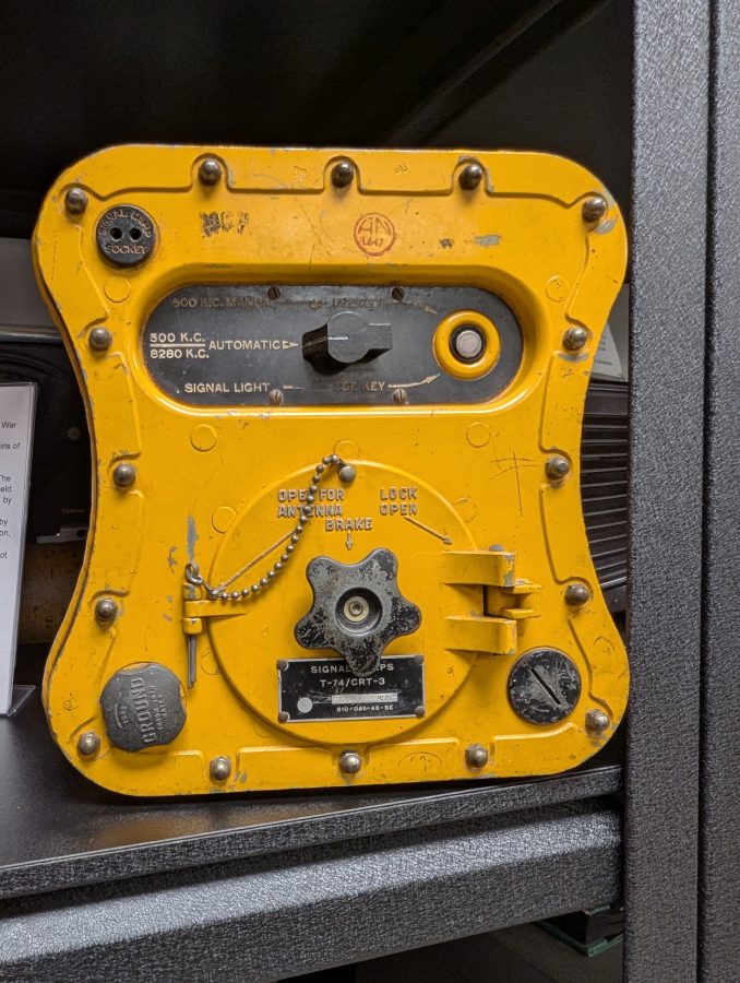
This is a WWII era life boat radio which transmitted on 500 KHz and 8,280 KHz. It was powered by a hand crank and could send an automatic SOS or a CW message could be sent manually by the key button. The round door on the front contained a wire antenna. After 1947, the HF Lifeboat frequency was changed to 8,364 KHz, which remained in use until about 1992.
There are several other displays on early telephones, the proximity fuses developed during WWII and so on.
The Asheville radio museum is located in room 315, Elm Building, A-B Technical Community College, 16 Furnihurst Drive, Asheville, NC.
Special thanks to Stuart Smolkin for coming in on his day off to give us a tour.