Another liquid-cooled GatesAir transmitter installation was completed for WYPR, Baltimore, MD. This unit replaced a Continental 816 which had a long life.
The area around the transmitter site is not the best neighborhood. The building was formerly the WBAL-TV transmitter site and was built circa 1947.
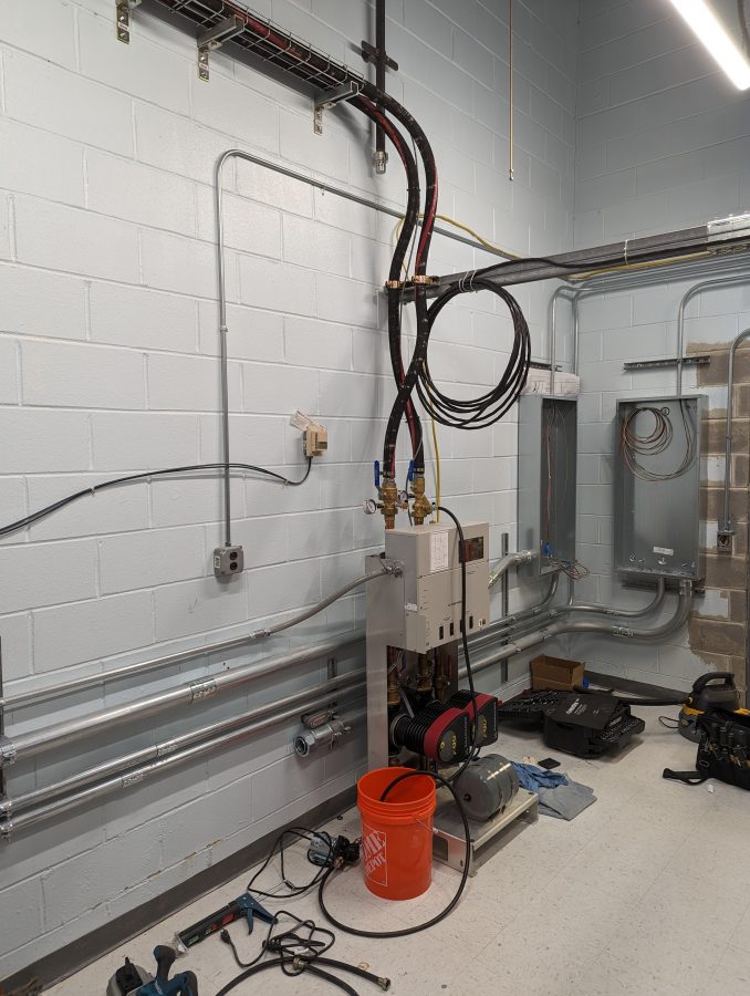
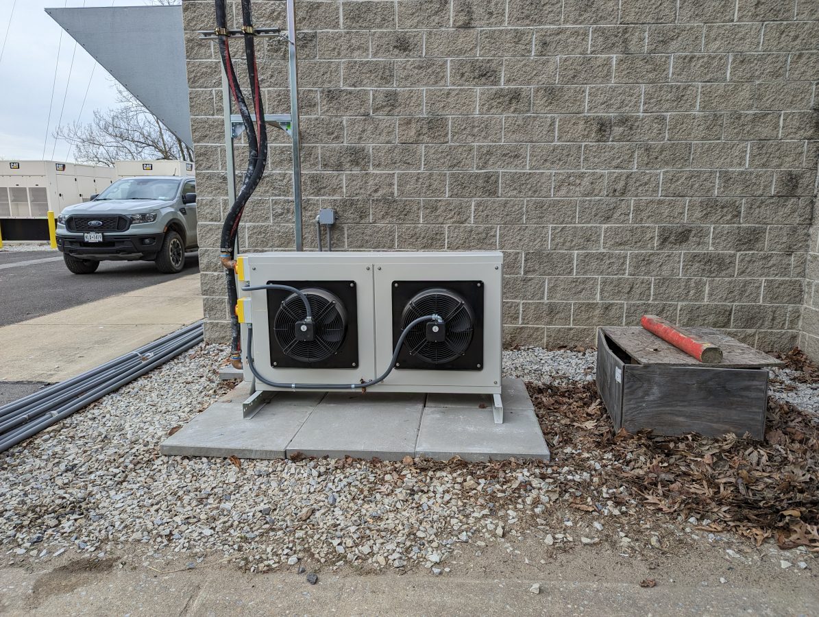
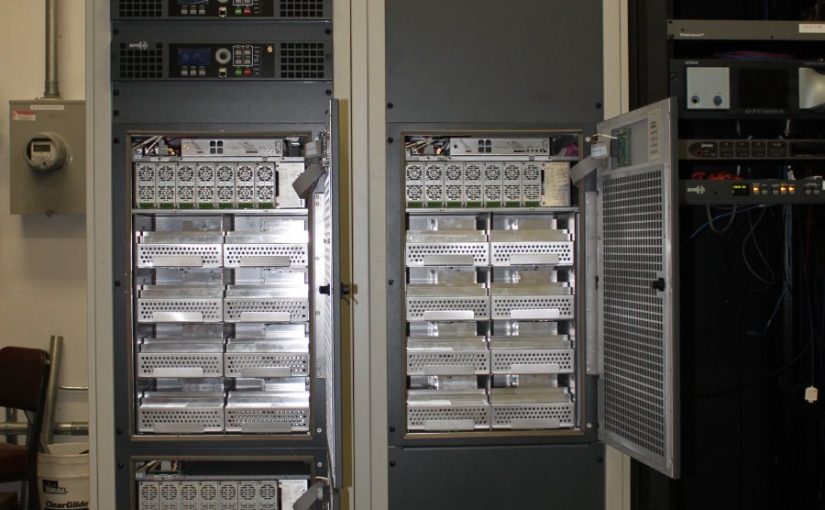
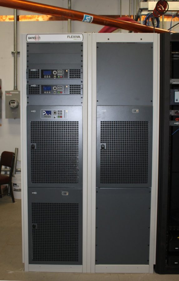
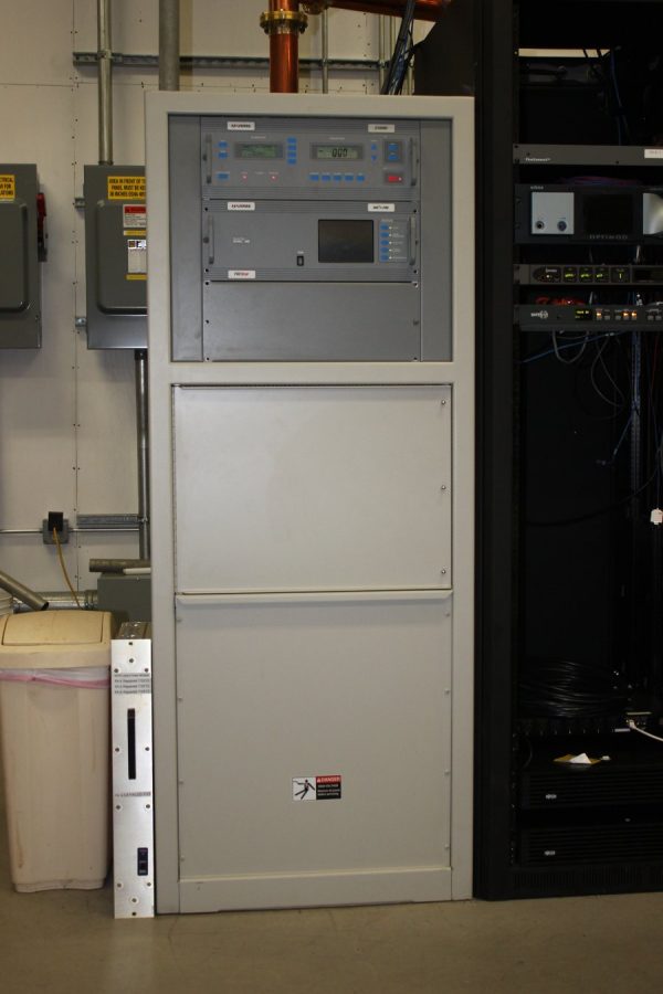
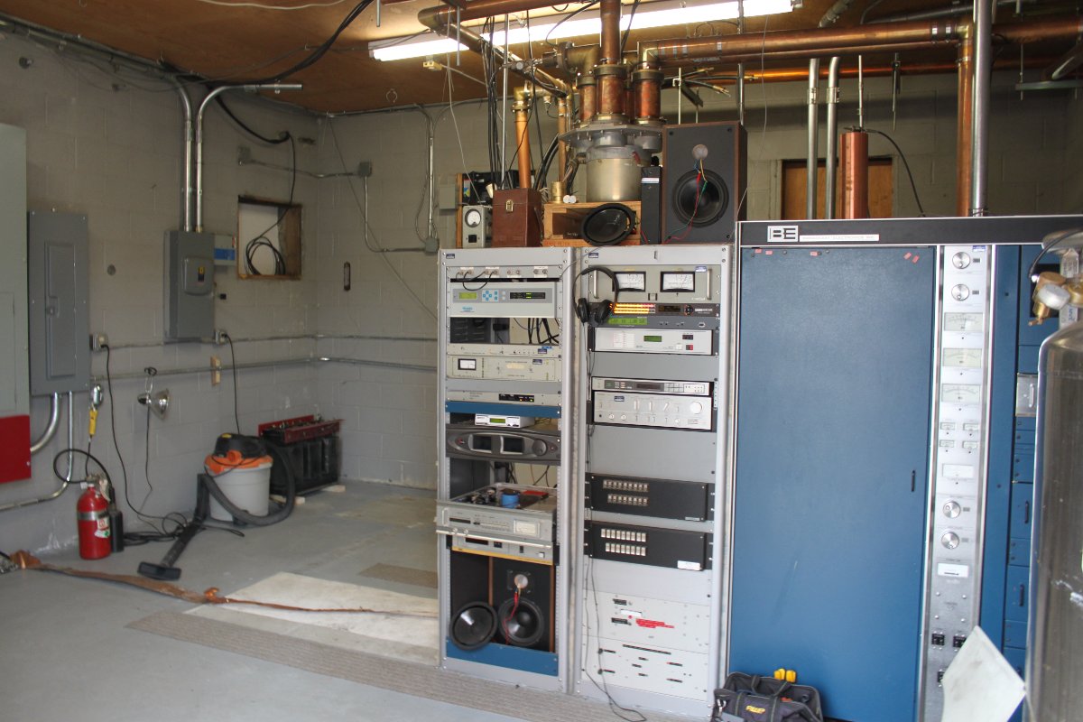
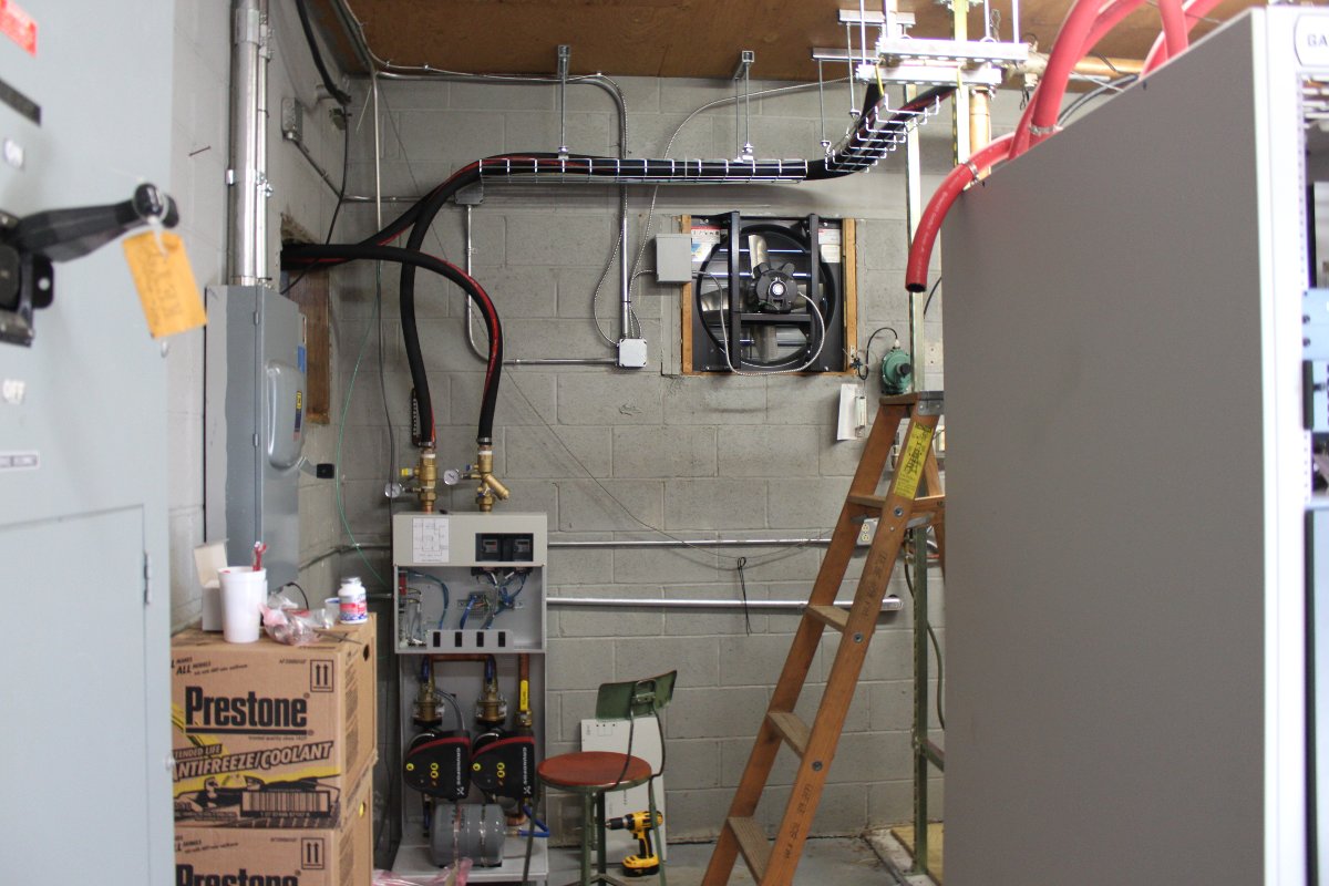
WYPR transmitter siteOriginal four-legged Blaw Knox self-supporting tower from the WBAL-TV daysPump station and HTF tubingWall-mounted heat exchangerFLX-20 transmitter
The transmitter room is a little tight, so it was difficult to get a good shot of the front of the unit.
The station is running HD Radio with -10 dBc.
This site has a strange 3-phase delta AC power configuration. The middle leg is at ground potential, and the other legs all measure 240 VAC to ground. I’ve never encountered that before. This is known as a corner grounded Delta, which gets rid of the high leg associated with most closed 3-phase delta systems.
Ultimately, all the leg-to-leg measurements are 240 volts, so the power supplies are satisfied. With these transmitters, the phase rotation does not matter because there are no actual 3-phase loads in the transmitter.
Inventory control, Home Depot Reisterstown Road, Baltimore, MD
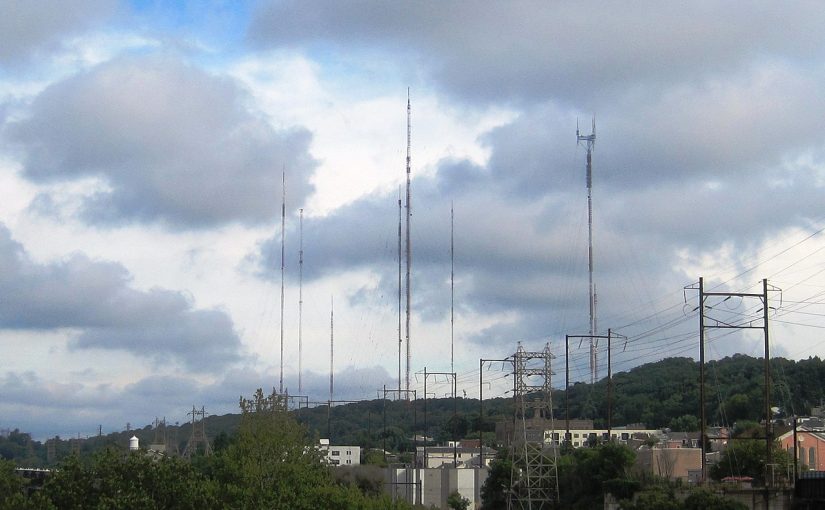
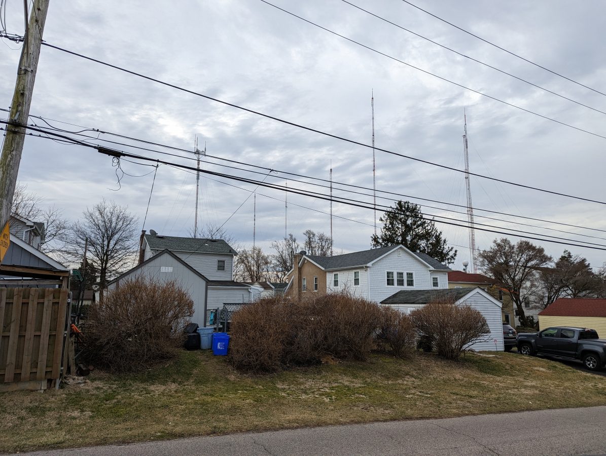
Greetings from the Roxborough tower farm, a place with roots. It is slightly northwest of Philadelphia, PA, and is home to many TV and FM stations. The public road that cuts through the tower farm is called Domino Lane because if one tower falls, they all fall. A comforting thought to those that live in the vicinity I am sure.
View from the residential neighborhood next to the site
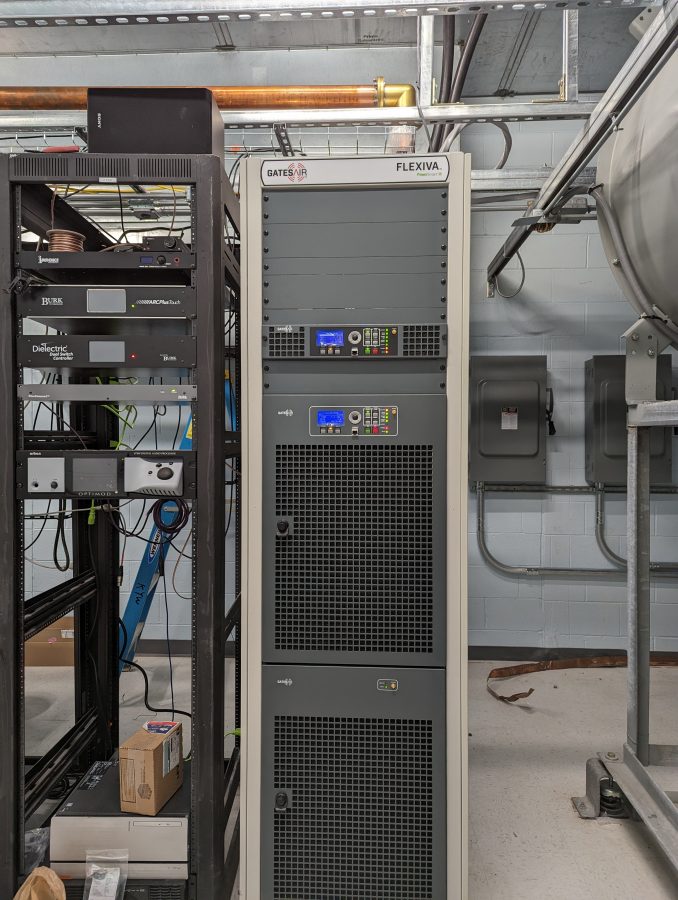
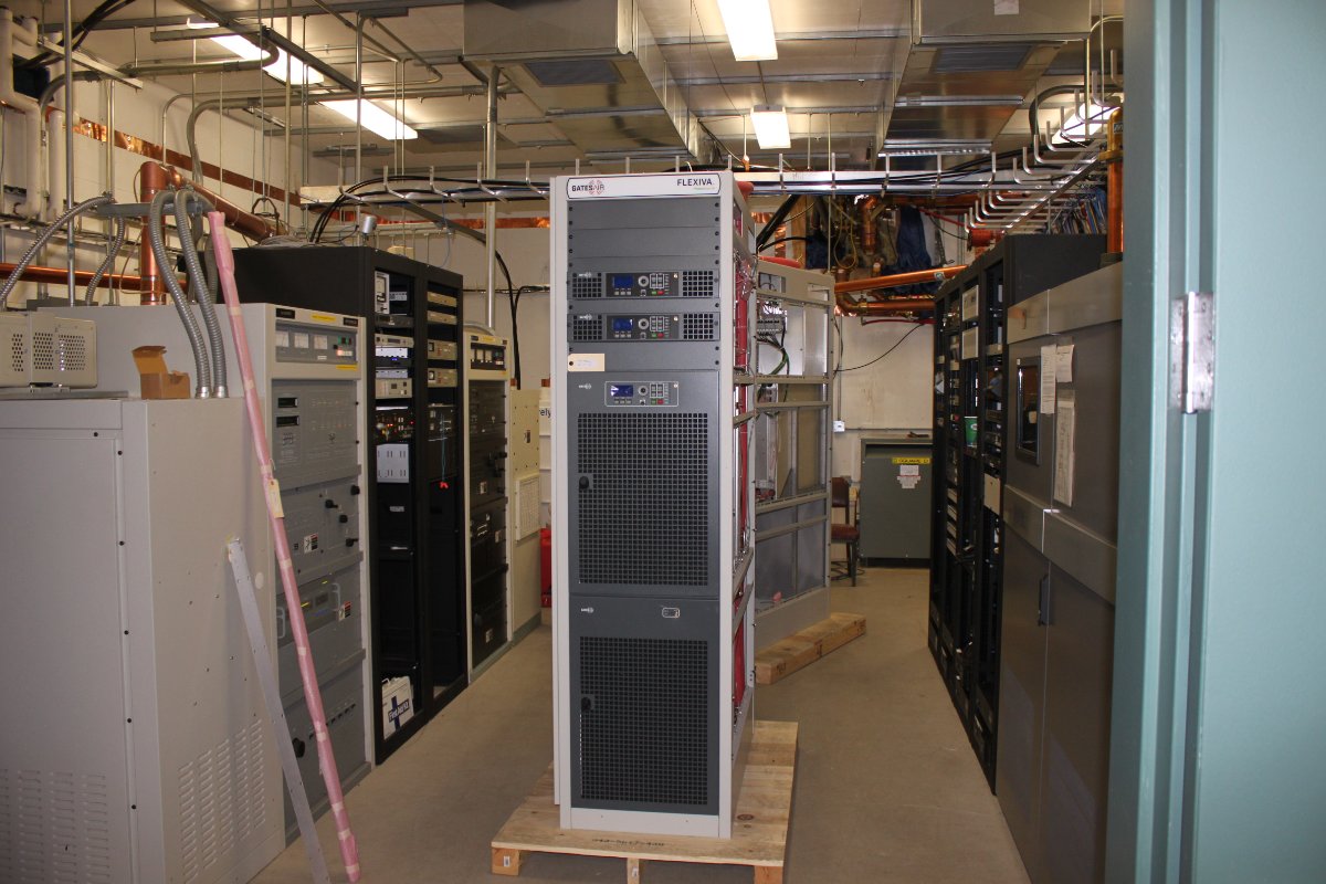
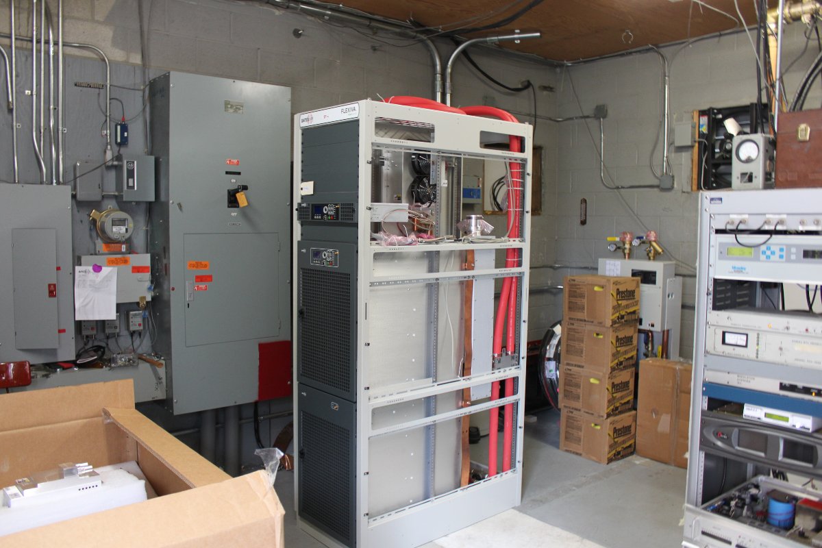
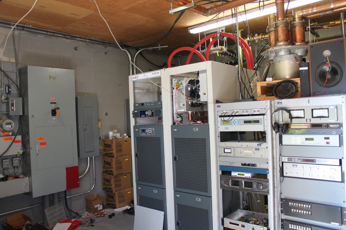
The reason for the visit; this rather nice GatesAir FLX20 transmitter:
Newly installed FLX20+HD, WRNB Philadelphia, PA
I must admit, I am growing rather fond of these transmitters. This unit is being installed because the station had to move from its old site, just down the hill. The tower owner is taking down the tower and building due to the age of the tower. Thus, it was moved into the KYW-TV building. If Wikipedia is to be believed, KYW-TV is the oldest TV station in Philadelphia, signing on in 1932.
The site is still being built as we were installing this transmitter. These days, the electricians are having supply chain problems like everyone else. There were delays getting the large electrical panel board and other necessary things for the build-out.
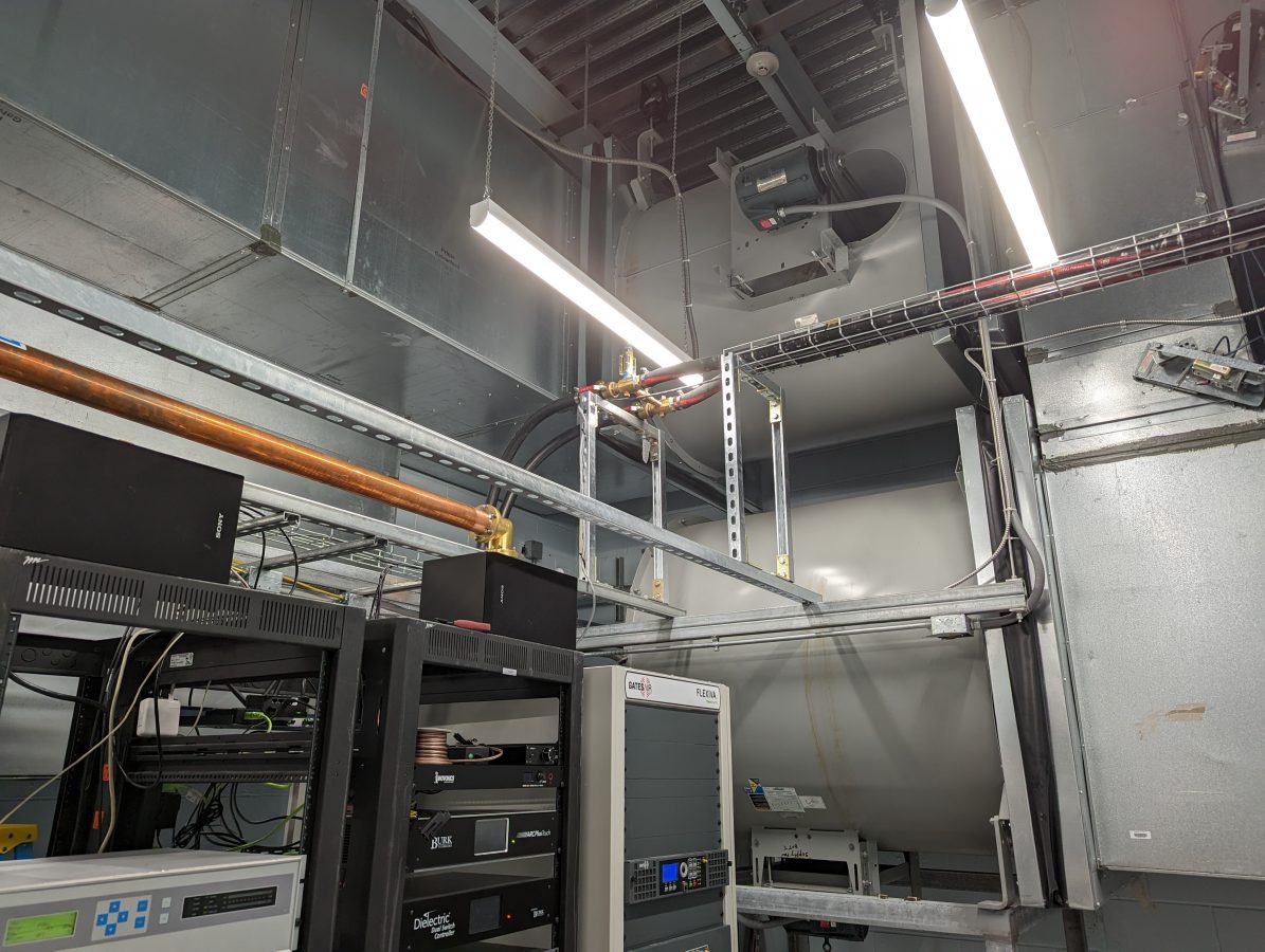
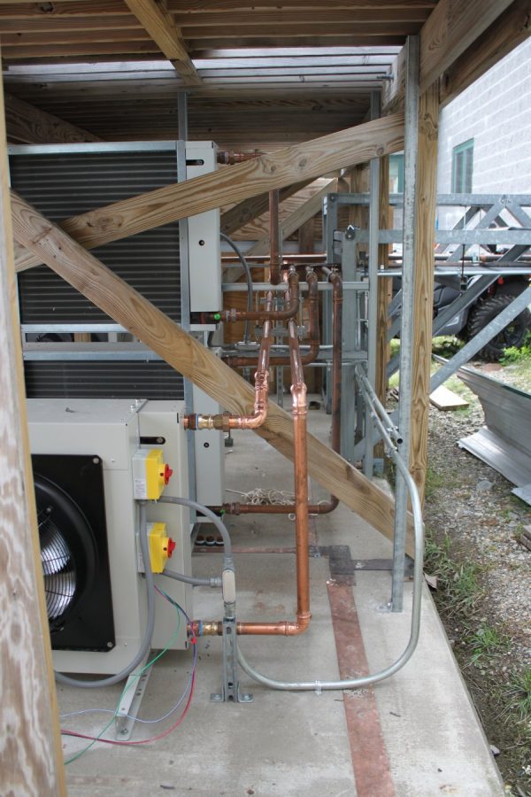
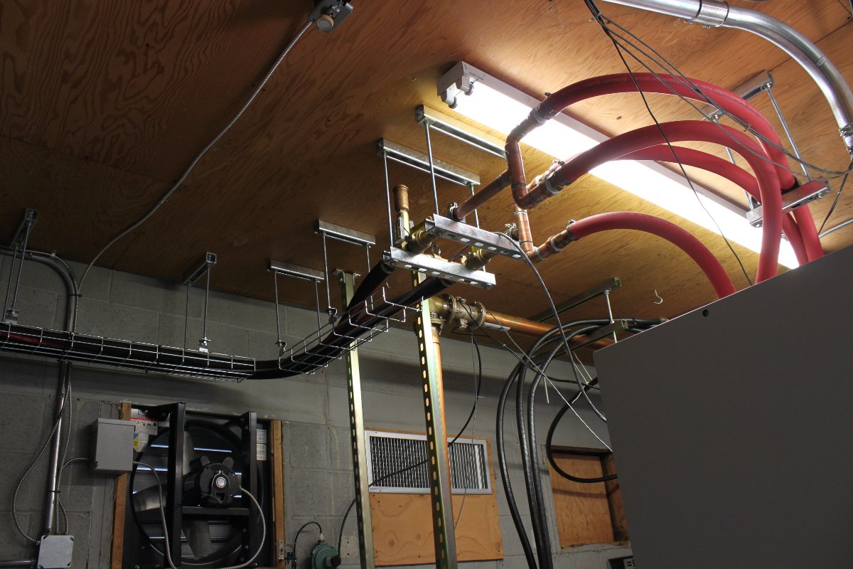
Cooling system high point, sight glass, and air purge valve
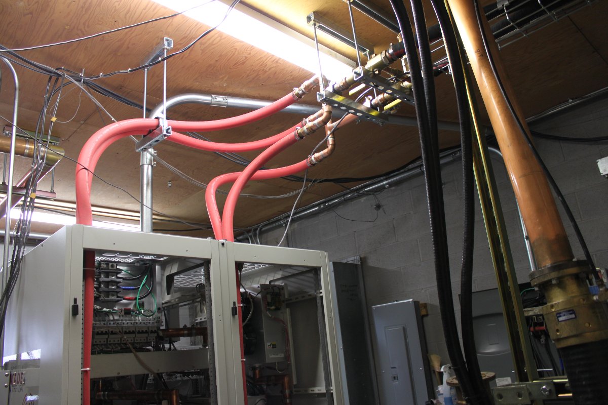
Overall, the installation went well. This system is using flexible hoses for the coolant loop. We have installed two of these liquid-cooled transmitters with 1 1/2 copper pipe. These days, copper pipe is expensive, so most are opting for flexible hose installation.
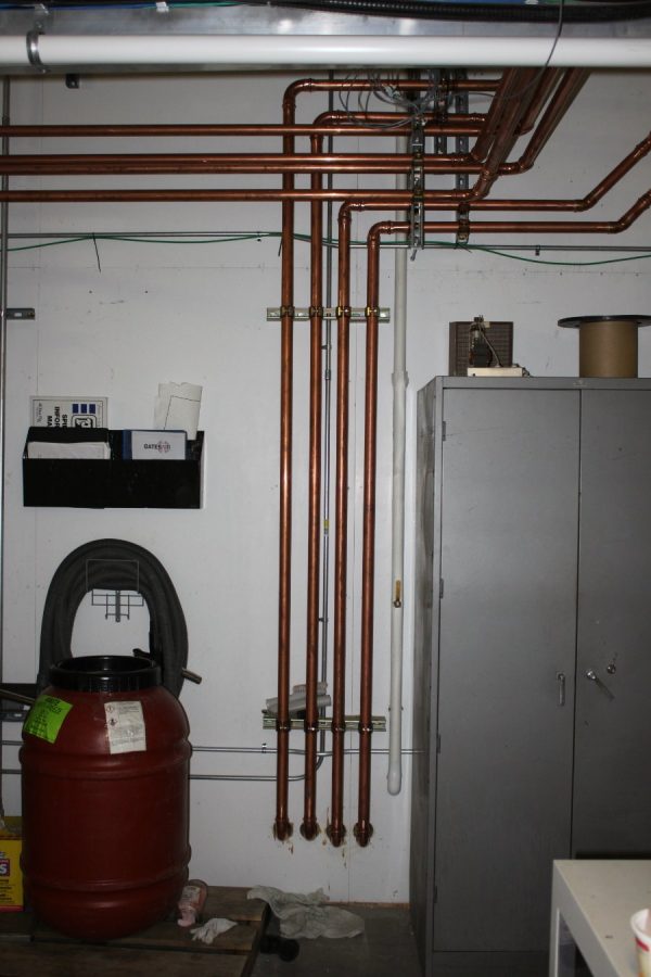
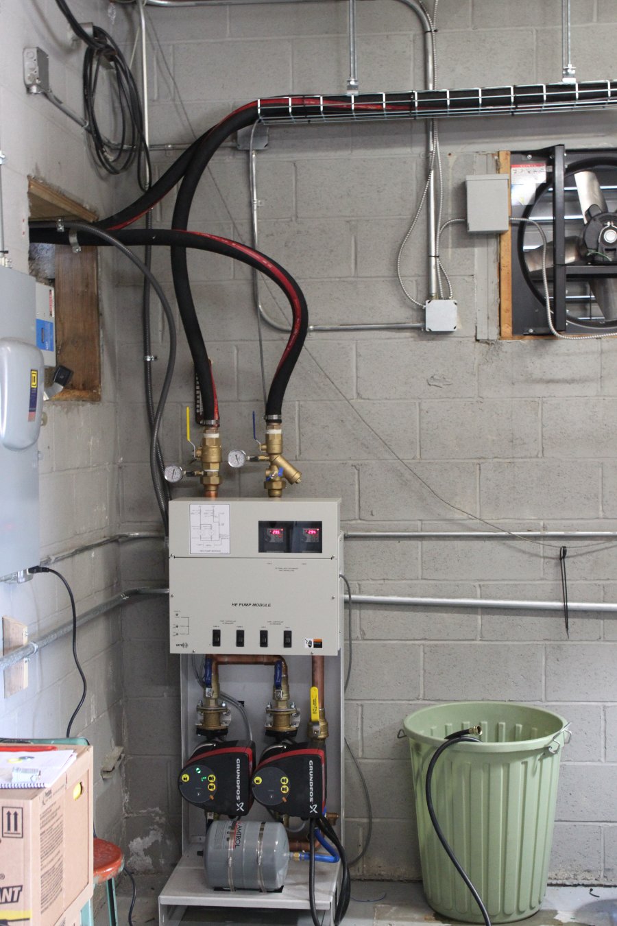
Pump Station; system top off
Topping off the pump station after 50/50 fillup. After the initial system fillup, it takes a while for all of the dissolved air to come out of the Heat Transfer Fluid (HTF). The extra steps with a liquid-cooled system are worth it, especially if the station is running HD. With the HD carrier on, the transmitter efficiency is 54% AC to RF. With a TPO of around 15 KW, that is a whole lot of heat that needs to be dissipated during operation. It is much cheaper to pipe the heat outside to a heat exchanger than to use several tons of AC to remove it from the room.
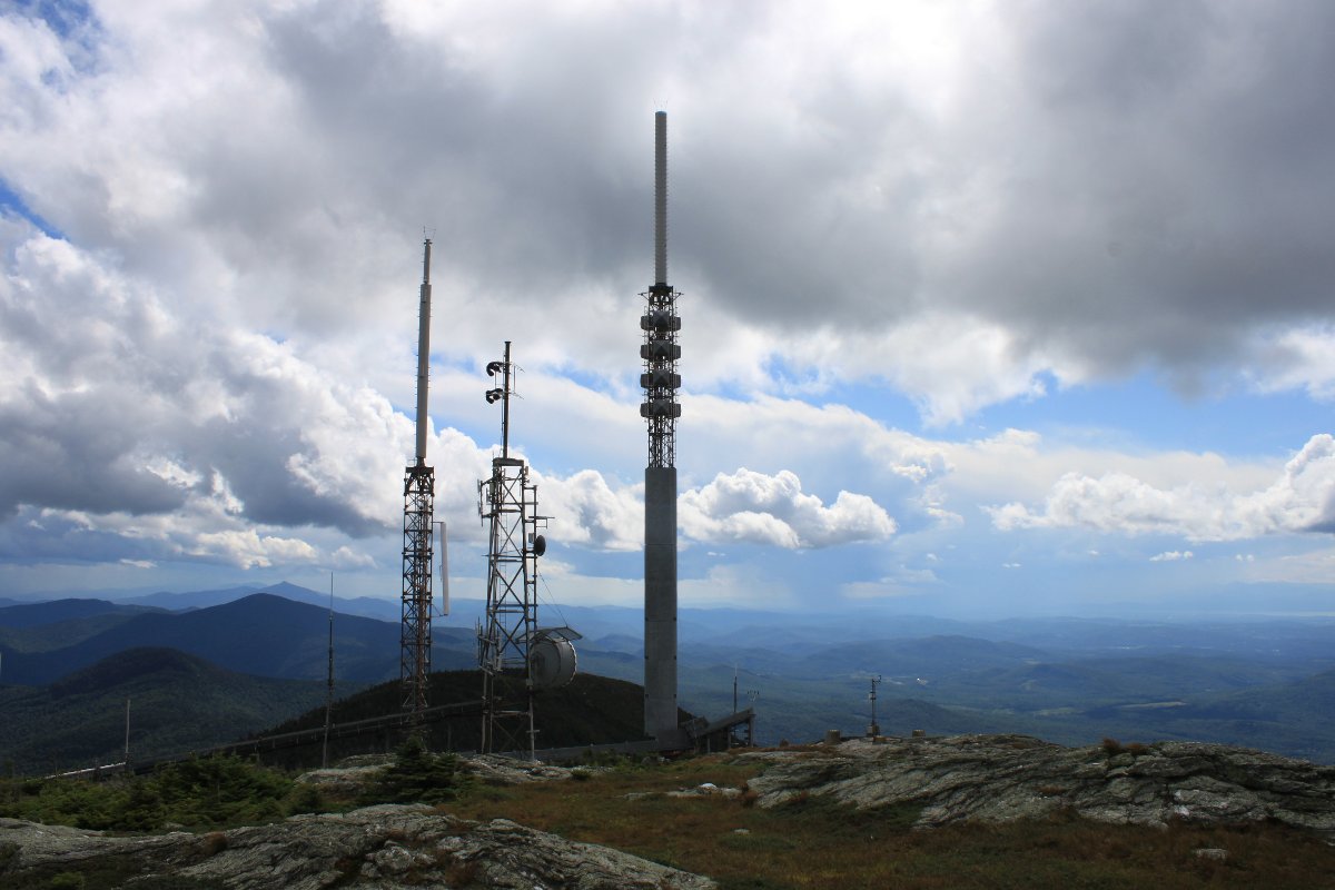
This is the second time I have installed one of these liquid-cooled transmitters. This time, it is for WVPS in Burlington, VT. WVPS is the flagship station for Vermont Public Radio. The station is a full class C, a rarity in the North East. The transmitter is located on Mount Mansfield giving it a HAAT of 2,717 feet (828 Meters), which is a good way up.
GatesAir FLX-30, WVPS Burlington, VT
This transmitter replaced the previous backup transmitter, a Harris Z16 unit from the early ’00s. There was nothing really wrong with this unit, it just was not a full power backup.
Harris Z16 transmitter
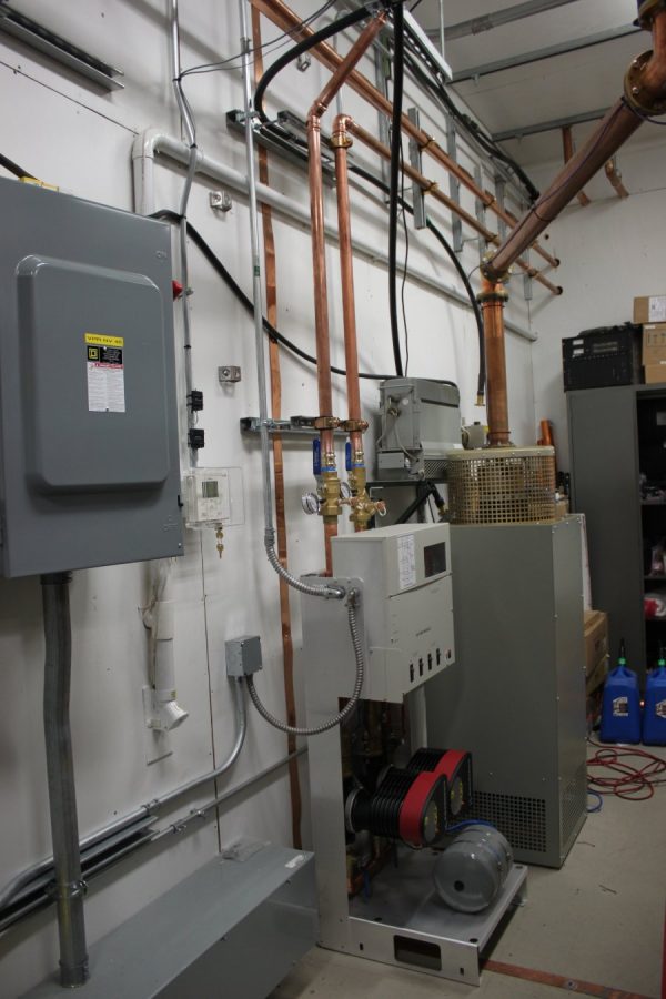
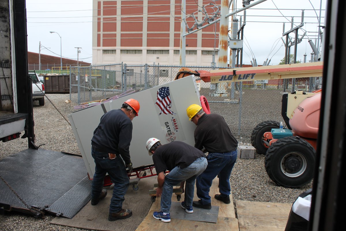
The new transmitter came in two pieces, which is typical for the 30 and 40 KW GatesAir liquid and air-cooled transmitters.
New Transmitter, being placed in Radio Transmitter room
For the cooling part of this installation, 1 1/2 inch type M copper pipe was used. This matches most of the other TV transmitters down the hall. In the same building are the transmitters for WCAX-TV, WPTZ-TV, WFFF-TV, and WVNY-TV.
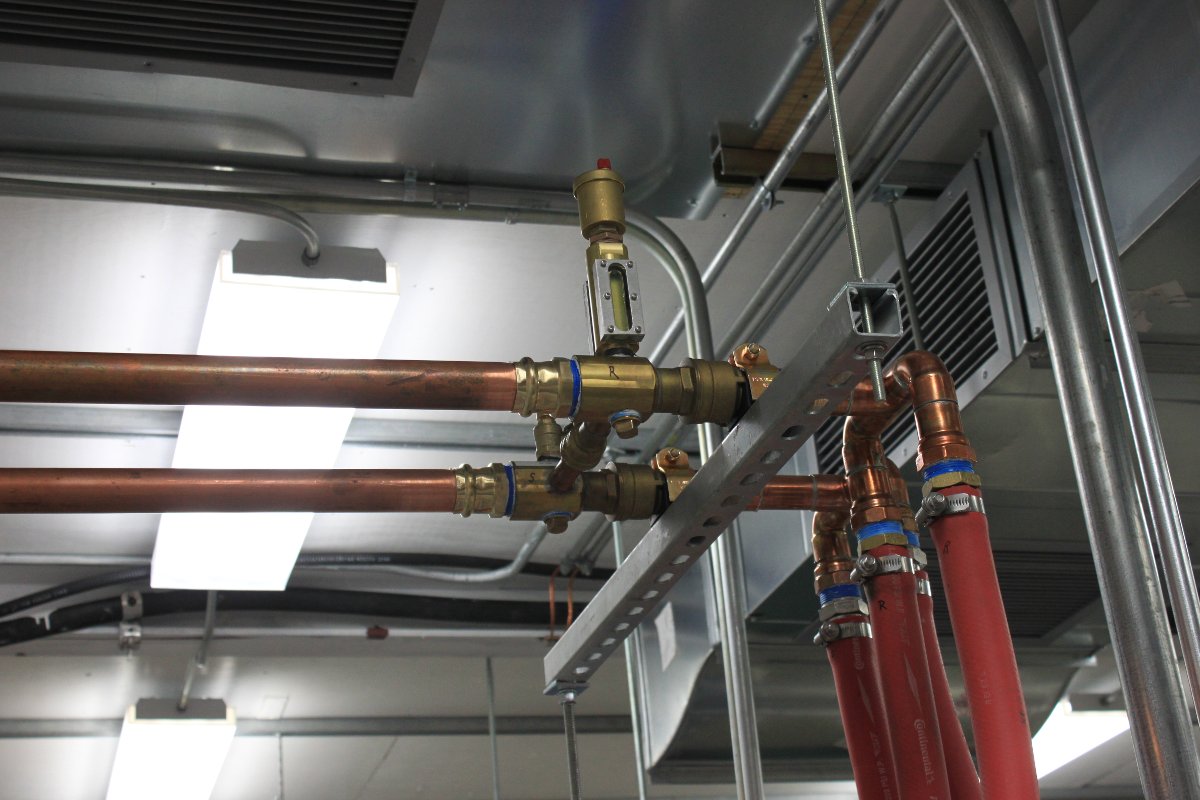
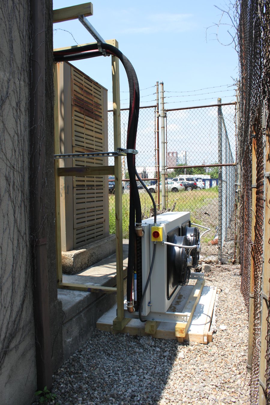
FLX-30 Heat Exchanger, outside with all the othersLiquid-cooled transmitter piping, WCAX’s left pair, WVPS right pairAir purge valve, sight glass, cross-connect and distribution manifold, above the transmitter
The highest point in the liquid-cooled system is the air purge valve and distribution manifold just above the transmitter. From here, everything slopes down to a few low points; the heat exchanger outside, the pump station, and the power blocks. This is to make it easier to drain if that ever needs to happen. There is also an air inlet valve to aid in draining.
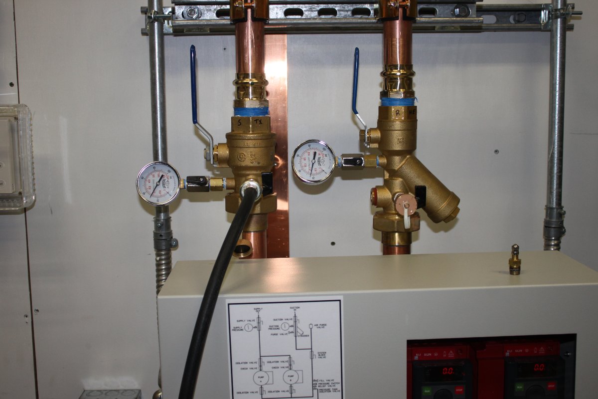
GatesAir pump station
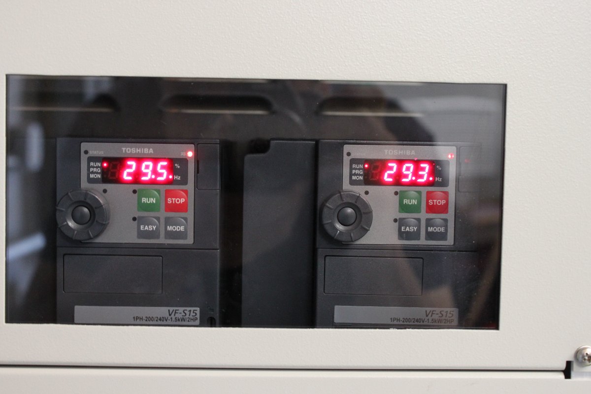
All of the cooling work is controlled by the pump station. The fans are connected to VFD modules, which control the flow of air through the Heat Exchanger.
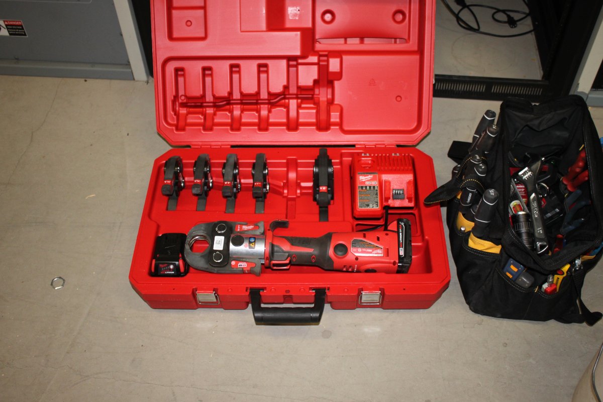
Milwaukee Press Tool
All of this plumbing work was greatly sped along with the use of this Pro Press pipe press tool. This thing is great! No more sweating connections. Dry fit a section to make sure that it is all cut correctly, then go to work with this and it is done in a matter of seconds. Of course, there are no re-dos, so the dry fit procedure is a little more important.
System flush and pressure test
Prior to filling with Heat Transfer Fluid (50/50 water/antifreeze mix), the system was first pressure tested with air, then filled with clean water for a 12-hour flush. The water was drained out and the filter screen was cleaned, then it was filled with the appropriate Heat Transfer Fluid.
Testing into dummy load, TPO is 25,995 watts with -14 dBc HD Radio
Final system checks, remote control test, and HTF top off and the transmitter is ready to go pending the HD Radio installation.
The GatesAir FLX-40 transmitter is my first liquid cooled transmitter installation. Previously, I have installed an air cooled Nautel NV-40, a V-40 and a couple of BE FM-35T/20T units. The WEBE transmitter site in Bridgeport, Connecticut is an interesting facility.
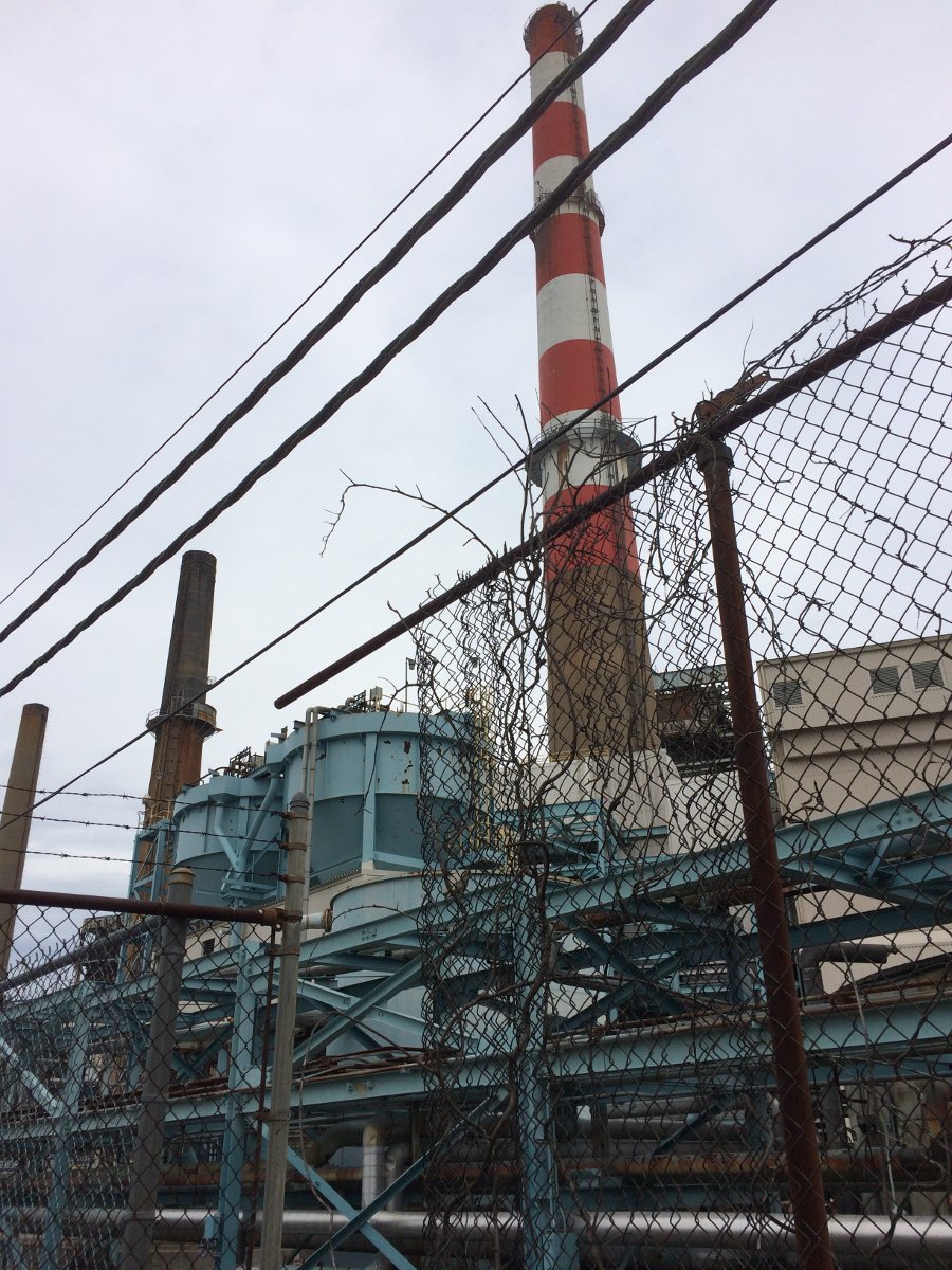
Smoke Stack, Bridgeport Energy, Bridgeport, CT
This coal fired power plant smoke stack which currently holds up the six bay, half wave spaced Shively antenna. The old BE FM35A transmitters are getting little bit long in the tooth. Thus, we picked one to scrap, the other will be kept for backup service.
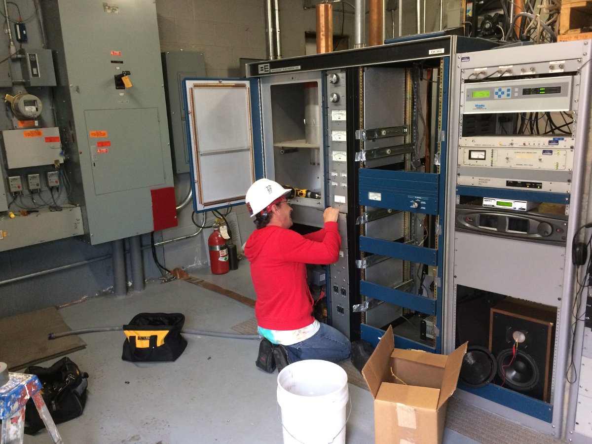
Scraping 34 year old BE FM30A transmitter
We saved a whole bunch of parts to keep the other FM35A on the air in backup service.
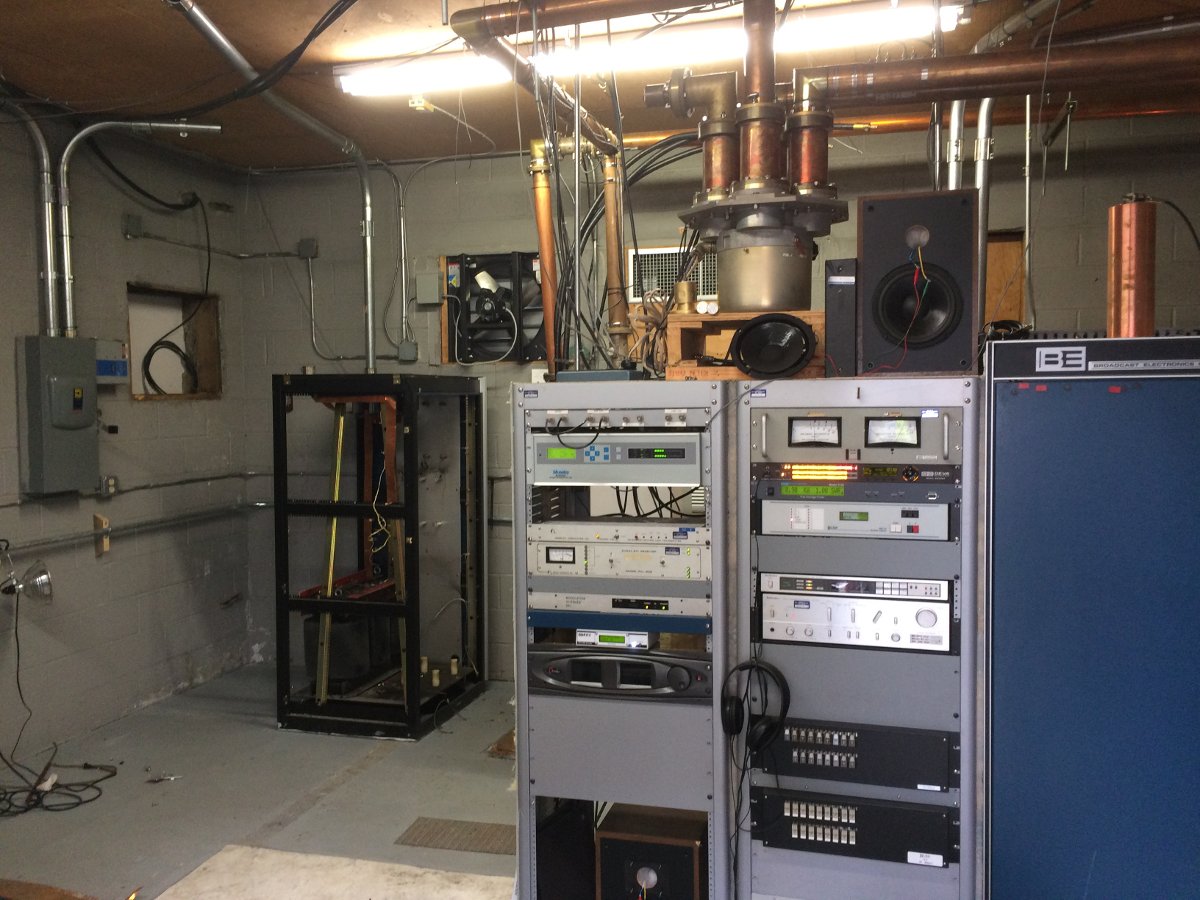
BE FM30A power supply cabinet
The power supply cabinet with that 500 pound plate transformer was the last to go.
On second thought, that plate supply transformer is a good spare to have
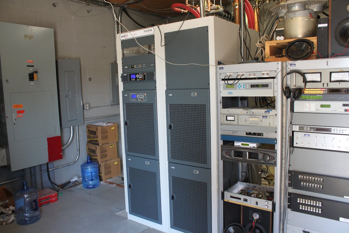
The FLX-40 came on a large truck. Fortunately, we were able to open the side gate at the power plant and get the truck to the front door of the transmitter building easily. The transmitter consists of two large cabinets, each with two 10 kilowatt power blocks. There is also a pump station and an outdoor heat exchanger.
FLX-40 cabinet two off the truckFLX-40 cabinet oneFLX-40 in place, cabinets bolted together
This transmitter design is based on the Harris digital TV transmitters.
FLX-40 pump station
The pump station and heat exchanger are the same systems used for TV transmitters. Liquid cooled units require a bit more planning on the installation end. The coolant piping should have a high spot from which everything else slopes down hill.
Send and return coolant lines
I put a 1/4 to 12 inch pitch on everything. Of course, there are several low points, the heat exchanger, pump station and bottom power blocks.
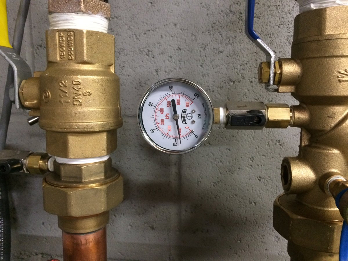
Holding steady at 16 PSI for 24 hours
After assembling the cooling system, we pressure tested it for 24 hours.
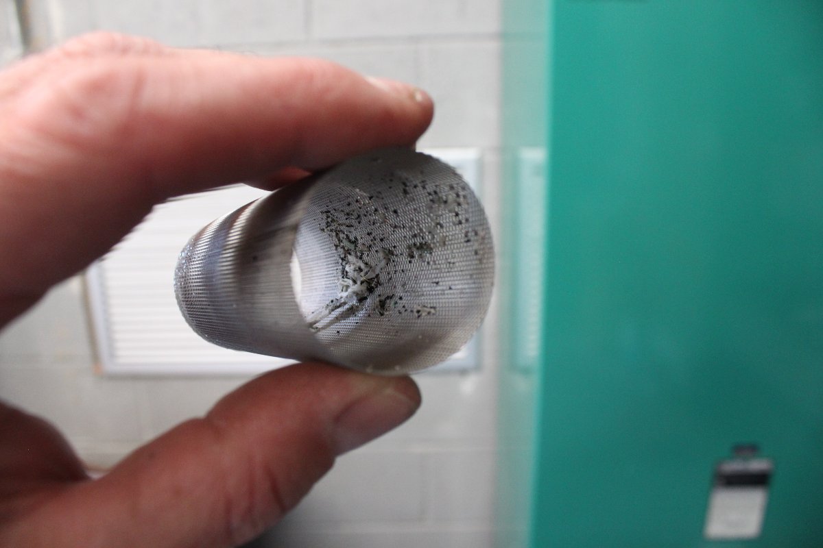
Installation debris in the coolant line strainer
Following that, we flushed the system with distilled water for several hours before we filled it with 40/60 glycol/water mix. Record low temperature in Bridgeport is -7 F (-22 C), thus a 40/60 mix will give protection down to -15 F (-26 C). The more water in the coolant, the better heat transfer capacity it has.
At the highest point in the system, there is a sight glass and an air purge valve
The pump station is controlled by the transmitter, which speeds up the pumps according to how much heat needs to be moved. In turn, the pump station control the fan speed on the heat exchanger outside.
FLX-40 pump station on line
The pump station runs with one motor most of the time. The other pump motor will run in the event of failure or if there is not enough flow through the power blocks. Each of the four power blocks has a flow rate meter on the return line.
Heat Exchanger Fan motor controllers, Variable Frequency Drive modules
Variable Frequency Drive (VFD) fan motor controllers show them running at half speed.
50 KW heat exhanger
GatesAir 50 KW heat exchanger mounted on concrete pad behind the building. Air flows out from the motor side.
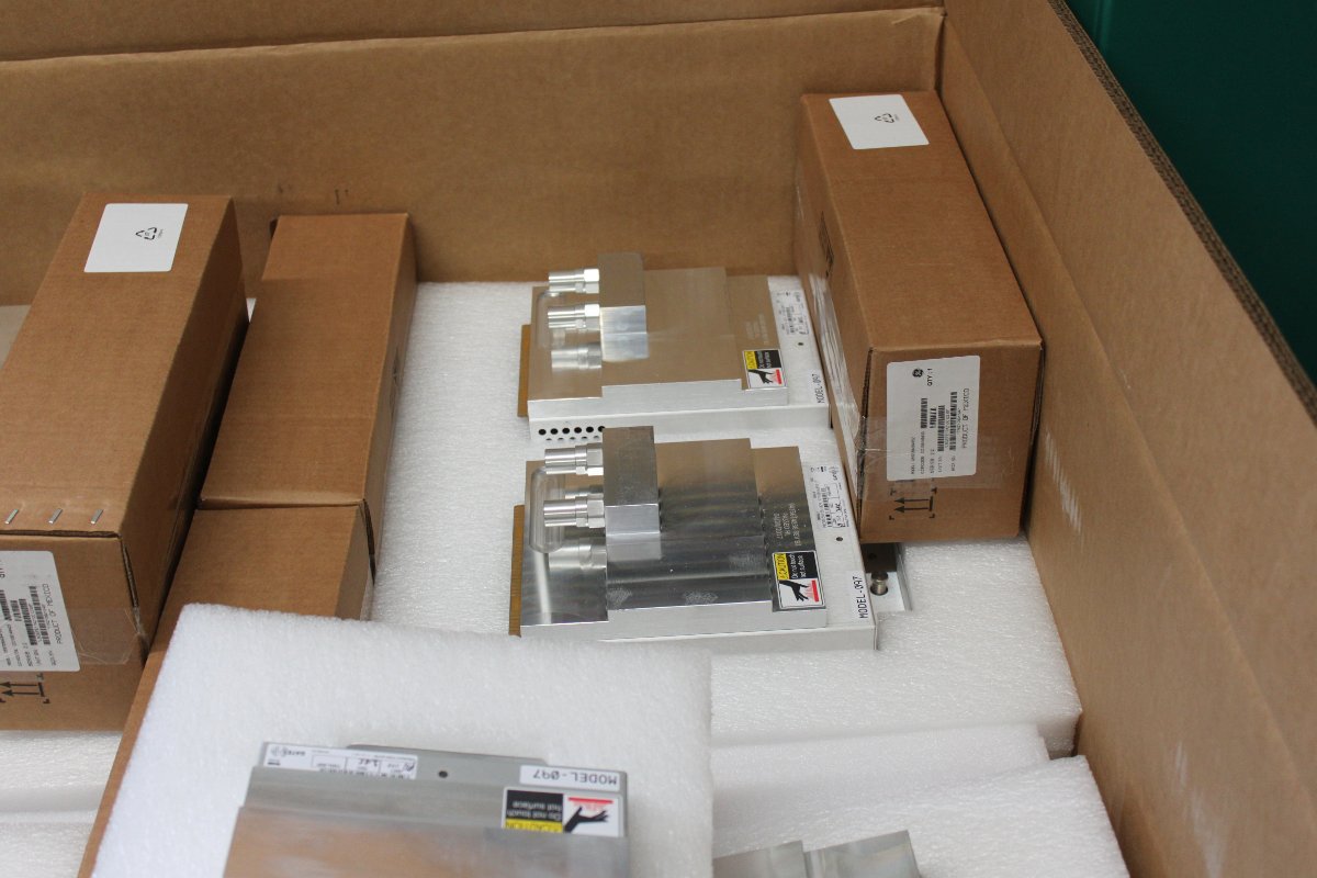
One of several shipping containers with modules and other parts for the FLX-40
As with most things, some assembly required. The RF modules needed to be placed in the power blocks according to their serial numbers on the test data sheet. This insures that the information on the test data sheet matches the installed transmitter configuration. The power combiner between the two cabinets as well as the reject load and directional coupler all need to be installed.
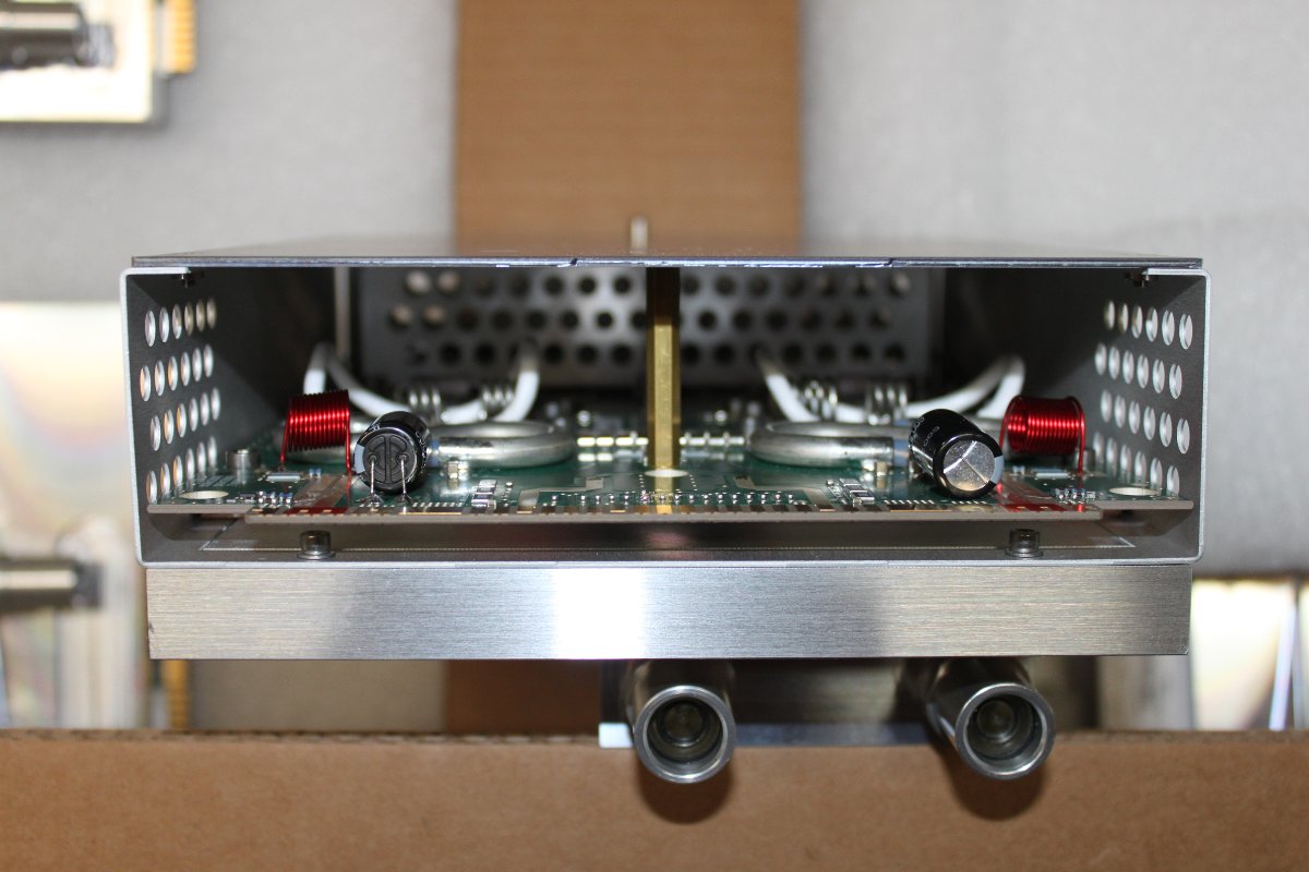
RF modules with large aluminium heat spreaders. Coolant flows through each module.
FLX-40 power amp moduleWEBE, Bridgeport, CT GatesAir FLX-40 on the air for the first time
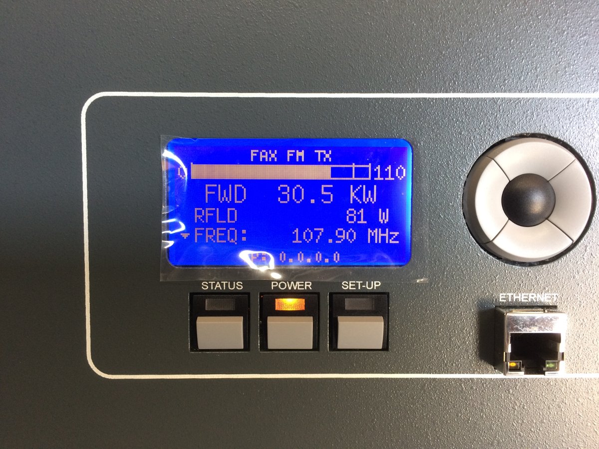
On the air!
FLX-40 into the antenna
We ran the transmitter for several hours into the antenna yesterday afternoon. The coolant system is still purging air, so we periodically needed to add water/antifreeze to the pump station to keep the pressure between 12-18 PSI. Eventually, the TPO will be 34 KW with the HD carrier(s).
All in all, I would say that this was a fun project. The liquid cooled transmitter had a few extra steps during the installation process, but not too difficult.