The GatesAir FLX-40 transmitter is my first liquid cooled transmitter installation. Previously, I have installed an air cooled Nautel NV-40, a V-40 and a couple of BE FM-35T/20T units. The WEBE transmitter site in Bridgeport, Connecticut is an interesting facility.
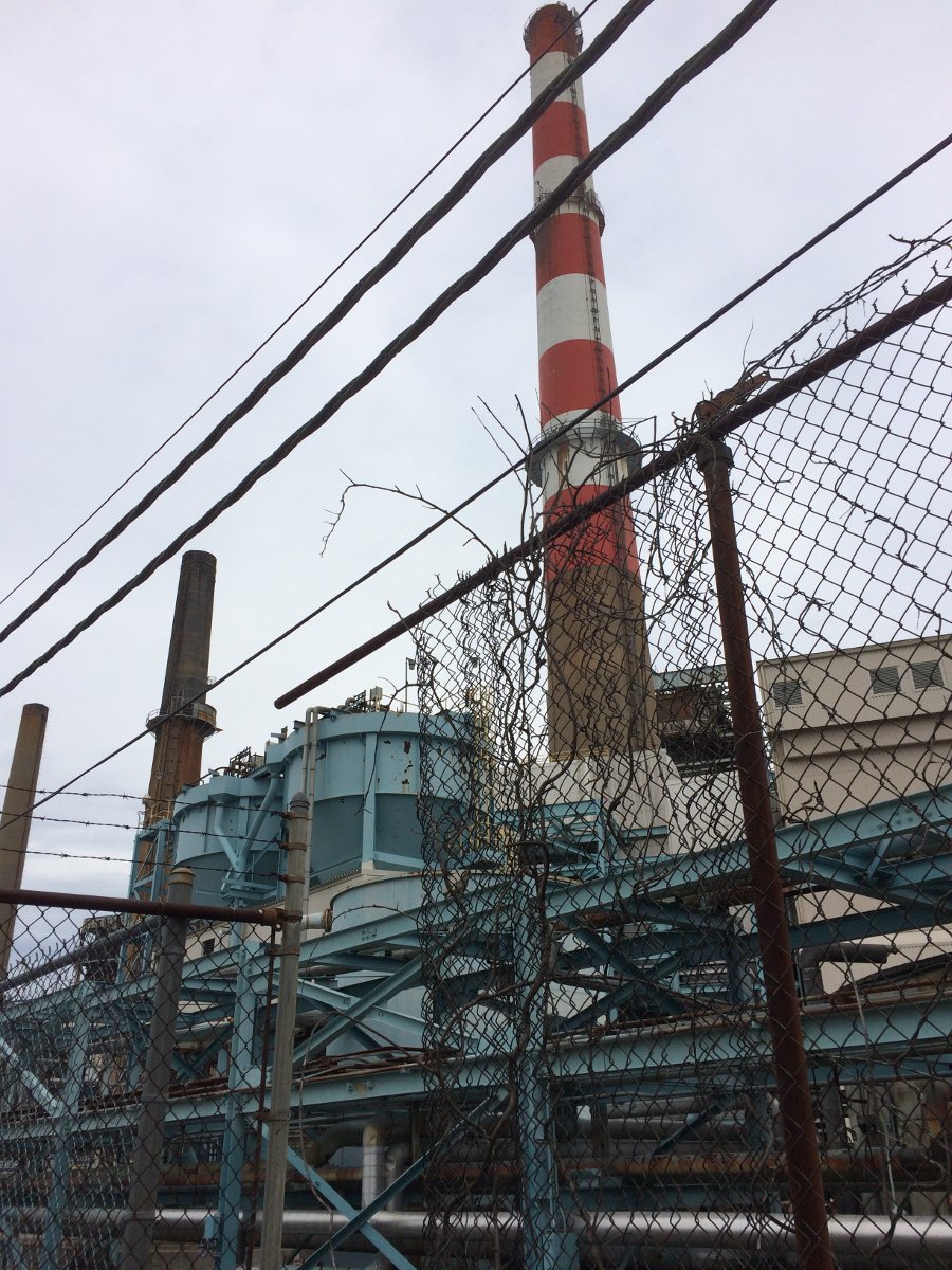
This coal fired power plant smoke stack which currently holds up the six bay, half wave spaced Shively antenna. The old BE FM35A transmitters are getting little bit long in the tooth. Thus, we picked one to scrap, the other will be kept for backup service.
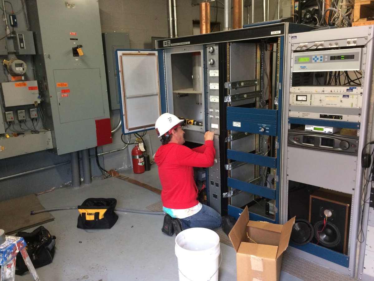
We saved a whole bunch of parts to keep the other FM35A on the air in backup service.
The power supply cabinet with that 500 pound plate transformer was the last to go.
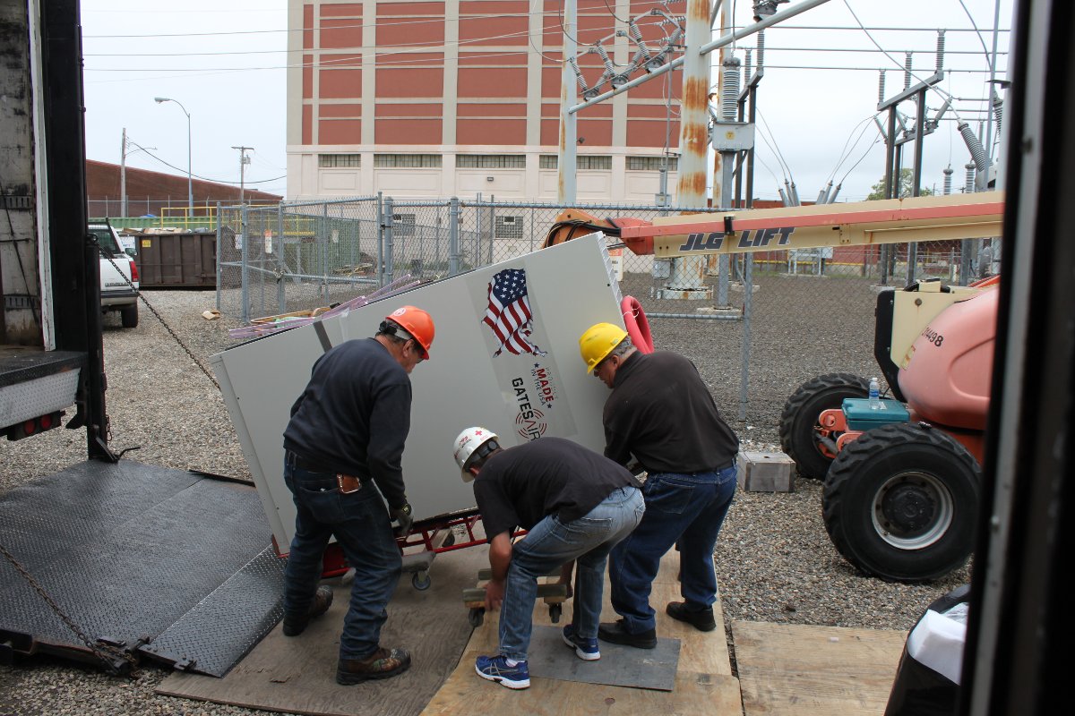
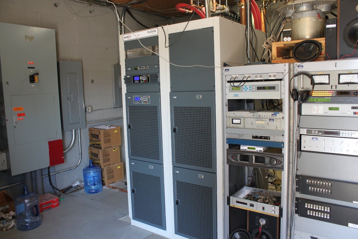
The FLX-40 came on a large truck. Fortunately, we were able to open the side gate at the power plant and get the truck to the front door of the transmitter building easily. The transmitter consists of two large cabinets, each with two 10 kilowatt power blocks. There is also a pump station and an outdoor heat exchanger.
This transmitter design is based on the Harris digital TV transmitters.
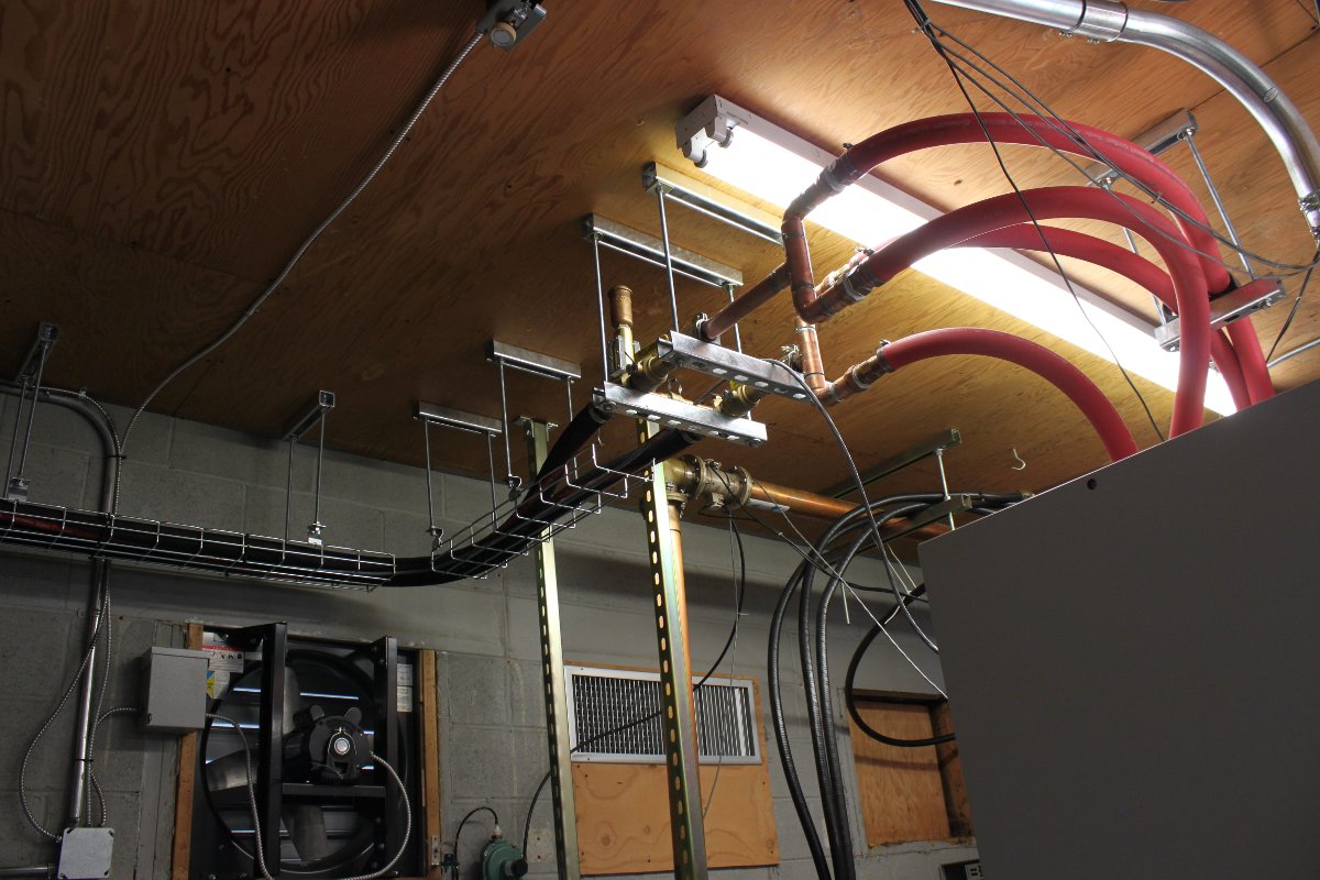
The pump station and heat exchanger are the same systems used for TV transmitters. Liquid cooled units require a bit more planning on the installation end. The coolant piping should have a high spot from which everything else slopes down hill.
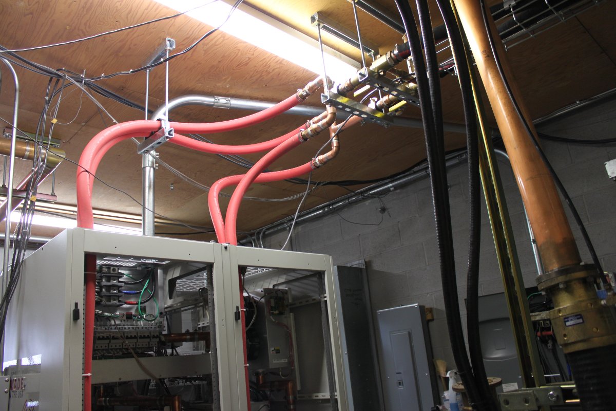
I put a 1/4 to 12 inch pitch on everything. Of course, there are several low points, the heat exchanger, pump station and bottom power blocks.
After assembling the cooling system, we pressure tested it for 24 hours.
Following that, we flushed the system with distilled water for several hours before we filled it with 40/60 glycol/water mix. Record low temperature in Bridgeport is -7 F (-22 C), thus a 40/60 mix will give protection down to -15 F (-26 C). The more water in the coolant, the better heat transfer capacity it has.
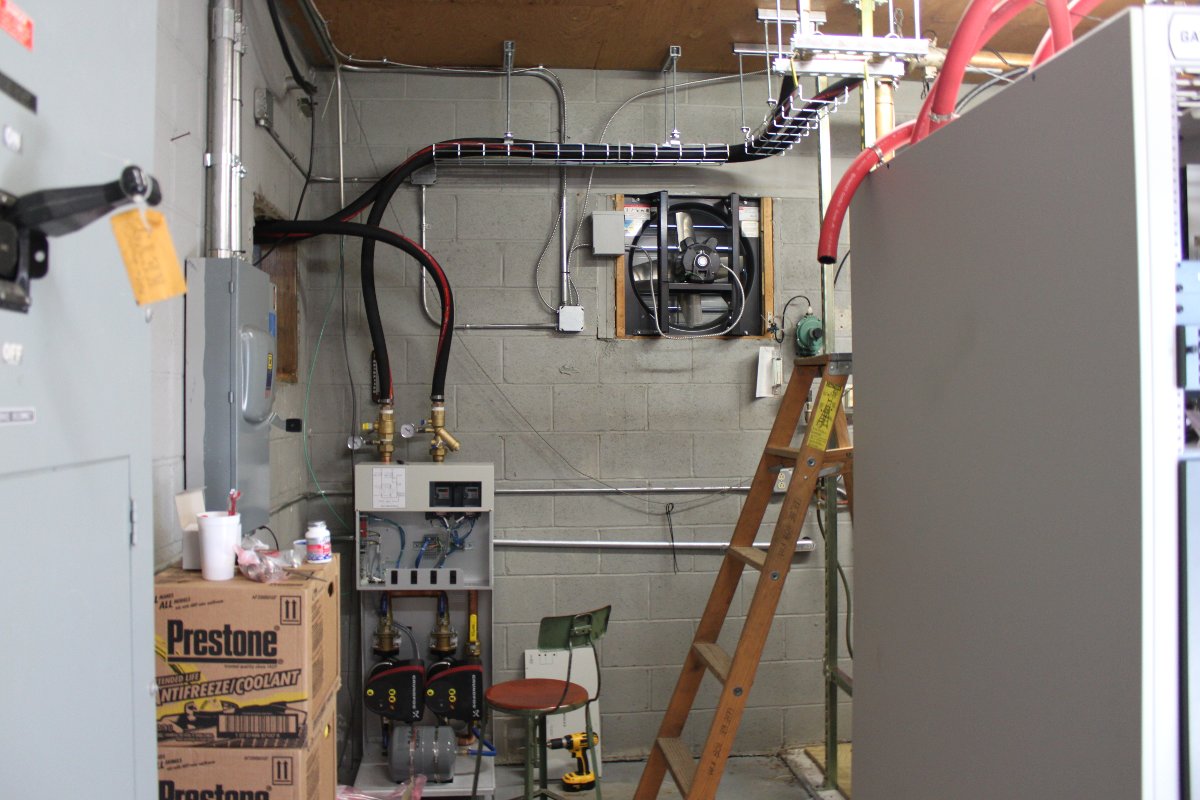
The pump station is controlled by the transmitter, which speeds up the pumps according to how much heat needs to be moved. In turn, the pump station control the fan speed on the heat exchanger outside.
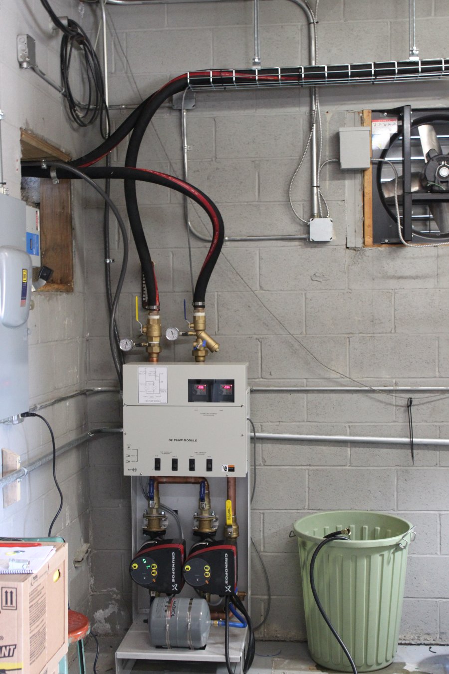
The pump station runs with one motor most of the time. The other pump motor will run in the event of failure or if there is not enough flow through the power blocks. Each of the four power blocks has a flow rate meter on the return line.
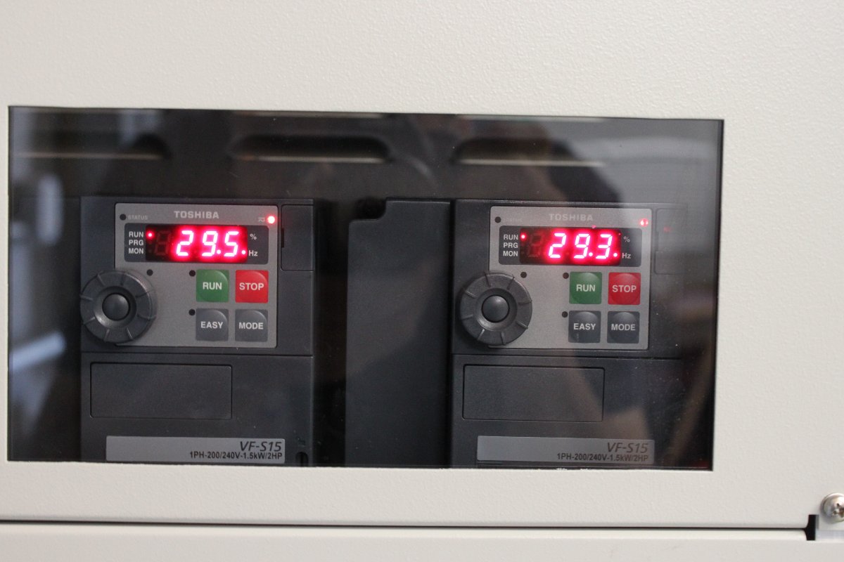
Variable Frequency Drive (VFD) fan motor controllers show them running at half speed.
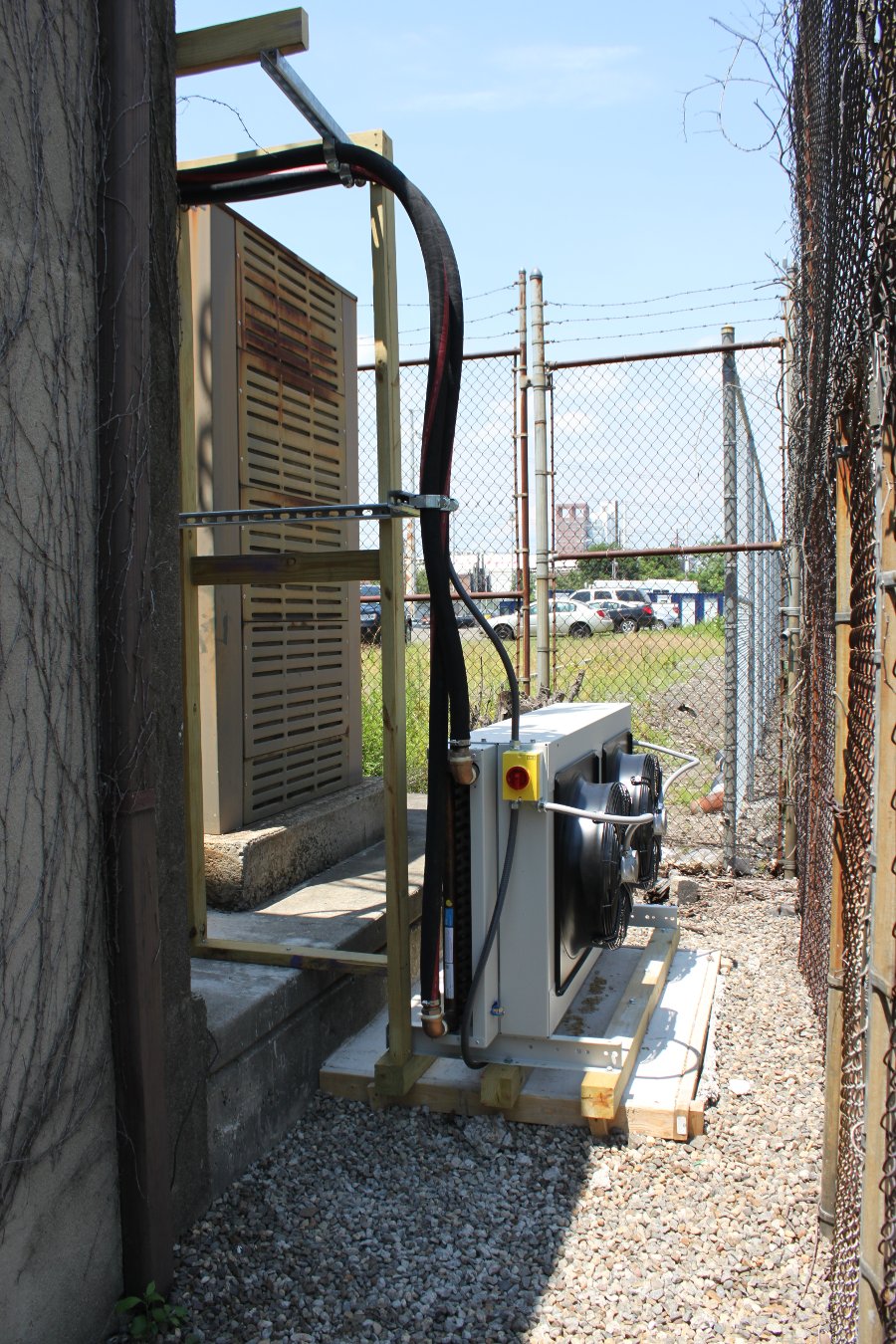
GatesAir 50 KW heat exchanger mounted on concrete pad behind the building. Air flows out from the motor side.
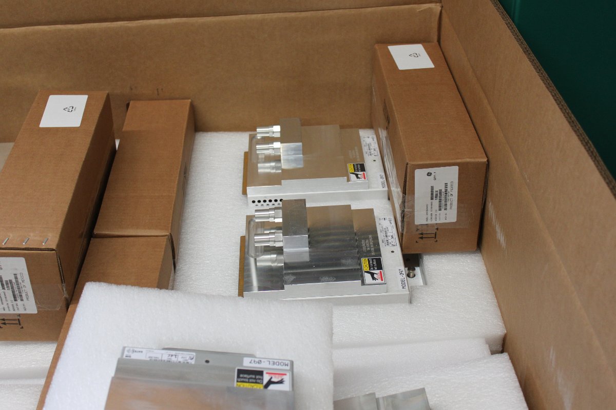
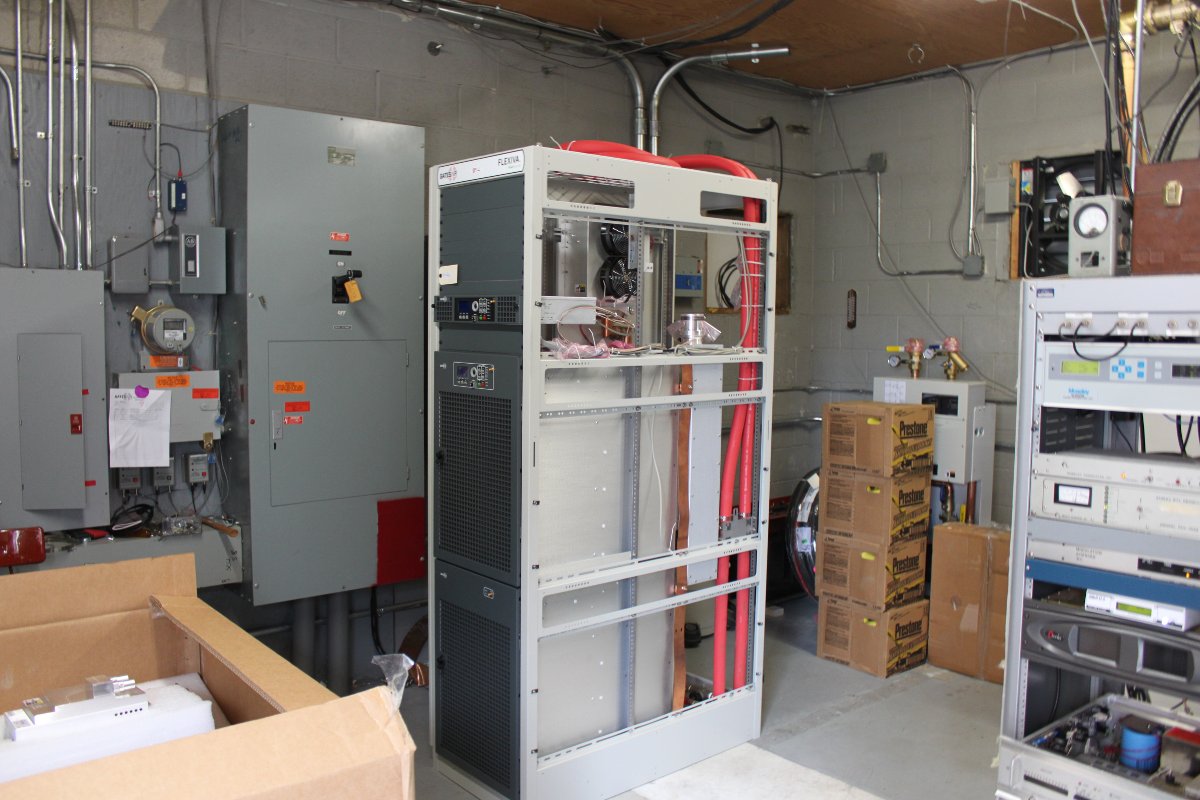
As with most things, some assembly required. The RF modules needed to be placed in the power blocks according to their serial numbers on the test data sheet. This insures that the information on the test data sheet matches the installed transmitter configuration. The power combiner between the two cabinets as well as the reject load and directional coupler all need to be installed.
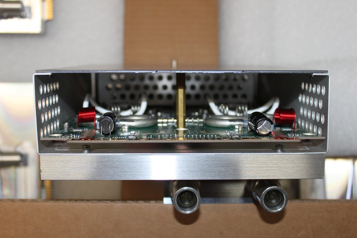
RF modules with large aluminium heat spreaders. Coolant flows through each module.
On the air!
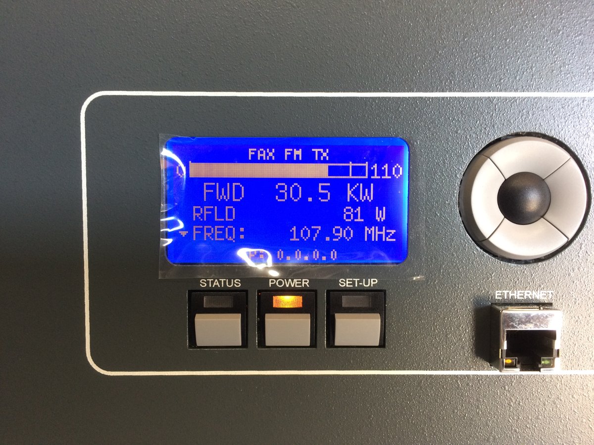
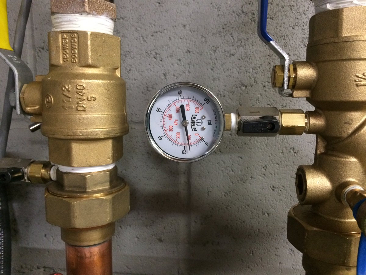
We ran the transmitter for several hours into the antenna yesterday afternoon. The coolant system is still purging air, so we periodically needed to add water/antifreeze to the pump station to keep the pressure between 12-18 PSI. Eventually, the TPO will be 34 KW with the HD carrier(s).
All in all, I would say that this was a fun project. The liquid cooled transmitter had a few extra steps during the installation process, but not too difficult.

Very NEAT install! I was going to ask you about the mixture, but you answered it w/o having to ask. Vy fb…do keep up the posts.
Help me understand why you’d install a complicated, liquid cooled transmitter over an air cooled rig? My past experience with UHF TV transmitters, these things can be a nightmare when stuff goes wrong. It’s great you kept one of the BEs for a backup. You’ll probably gonna need it.
Nice Install Paul! Very Neat.
Excellent job Paul. WEBE sounds great.
Rich, Don and Jerry, Thanks!
Scott, I believe it comes down to floor space and electricity costs. They wanted to reactivate their HD1/2/3 channels and the high level system installed 12 years ago was decommissioned and moved. Plus, they BE transmitters are getting old, very old. Also, using the liquid cooled system will reducing air conditioning loads and reduce operating expenses (electricity). As far as maintenance goes, time will tell.
Scott,
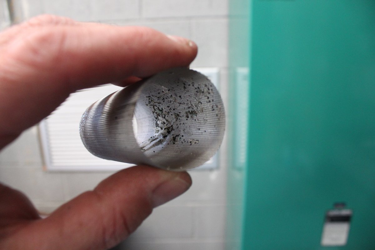
Having maintained liquid cooled transmitters for close to 20 years, I can tell you, they aren’t anywhere near as bad as what was around 25-30 years ago. I can count on one hand all the cooling system issues I’ve had in the 20 years. One was an installer’s error (never, ever, over tighten brass!). With that said, there is a touch more work to be done with the liquid systems; get the glycol tested by Dow once every 2-3 years, keep an eye on the filters, and most important, test all the flow cut off safety devices. The efficiency with a liquid cooled rig makes the price worth it, especially at a high power level. (Paul when the time comes for you to have the testing done, I have the right contacts to have the test completed).
Also we run 50/50 DowthermII at our site with external (outdoor) exchangers. Is it true the new rigs use Ethynol instead?
— Mike
I concur with Mike, liquid cooled rigs are very reliable and trouble-free when installed and maintained properly (although my preference though would be to steer clear from anything produced in Quincy. The Rohde & Schwarz THR9 liquid-cooled transmitter would be my #1 choice).
I recently did a cost-comparison when looking at replacing a pair of 20kW transmitters. Option 1 was to install a pair of Nautel NV20LT units, Option 2 was a pair of THR9 units, and Option 3 was a single THR9 configured for dual 20kW operation (yes, that’s a pair of 20kW transmitters in one rack!)
Option 1 required lots of air conditioning to move the heat outside.
Option 2 & 3 only required a small wall-mount unit to cool ancillary gear.
The liquid cooled options were going to potentially save the customer approx $350,000 over 10 years in operating costs (mostly in electricity and HVAC servicing fees).
It will be interesting to see if Paul’s client notices a similar cost-saving in the long term.
Disclaimer – I’m obviously biased, having been with Nautel for 27 years. 🙂
David, I’m curious how you obtained the $350k savings over 10 yrs.
2 x NV20LT both running full tilt at the same time produce just under 60,000 BTU/hr of heat. Using the worst case numbers I could find online, that translates to roughly 550.00/month, or 6600.00/yr for electricity to drive a 5 ton air conditioner (I didn’t allow for building heat load or convection heating in my math, because that would be the same in both cases). Allowing for inflation, that works out to around 75k over 10 yrs.
I couldn’t estimate HVAC service, but I know there are also service requirements to liquid cooling (coolant inspections every few years, pressure testing, filter replacements, pumps, etc.), so I’m curious as to what I’m missing that made up a almost 30k a year difference?
Overall efficiency of the two transmitters is pretty close – the NVLT is 72% AC to RF, the R&S from their website states “up to 75%”, which makes sense – but 3% difference, with both transmitters running at 22kW, works out to 20,736kWh/yr, or around 2500.00/yr, depending on local electricity rates. I’m sure I’m overlooking something and I do these types of comparisons almost daily – if whatever I’m missing makes that big a difference, I need to get educated so I’m not misleading anybody.
Thanks!
Jeff,
While I don’t know the details of Davids calculations, the savings can be large in some locations. I can tell you that from our experience working with customers, they often spend much more a year maintaining the air conditioning system, and replacing compressors every x number of years on their cooling system than they do on the transmitter maintenance (HVAC guys are not cheap). This is part of what drives some the savings of liquid cooling. None of us really think about the rest of the cooling when we compare air cooled transmitters to each other. As noted the liquid cooled systems around high power tube TV transmitters were not as reliable as today’s solid state systems, so a lot has changed.
If you are in a cooler climate, and simply use an exhaust fan to move air through the transmitter site, then the savings are less. If you however have a closed loop system, and are in a warm climate, there are significant operating and maintenance costs each month to run the AC beyond the cost of electricity. Also the efficiency numbers you selected are typically used for analog FM, the HD efficiency numbers, especially at elevated side band levels are lower adding to the heat load. One additional benefit many see is that they find the transmitter remains a bit cleaner than if you are running a bunch of air through it.
Is liquid cooling for everyone, no. If you have lower power levels (under 20kw), run FM only, are in a cool climate and use outside or filtered air, then you are not likely going to see the pay off vs complexity (running an air cooled transmitter in an open room with thermostatically controlled exhaust fan is pretty simple). If however you have higher powers, run HD with elevated side bands, run closed loop AC in a warmer climate, it can be a great solution. Again kudos to Paul, Pete and the Cumulus team for a nice install!
One other thing to note; this transmitter replaces a high level combining system for HD Radio. The former HD Radio system used a Harris Z-10 transmitter running 1,600 watts into a dielectric high level combiner, which dumped a lot of waste heat into the combiner room. The electric savings is not only for the air conditioning to remove the waste heat from the air cooled BE FM35A transmitter, but also the Z-10 and all the waste heat associated with HD Radio transmission. As this is in the Northeast, electricity is rather expensive. Using outside air to cool this site (except in emergencies) is out of the question due to the power plant emissions. Thus, the savings in electricity costs alone will be quite large.
Replacing the 31 year old BE FM35A transmitter with something newer, plus the ability to do HD 2/3 make this a pretty sound investment.
Mike, we used Prestone F2100 coolant, which was shipped with the transmitter. This is Ethylene Glycol, same as used in vehicles.
GatesAir FLX-40 transmitters are solid units. You did a great job with your installation of it and getting a working back-up transmitter.
Hi Paul, that was a great article. If you ever get the opportunity it would be nice to see some pics of the FLX-40 power amp module in more detail.
I think the liquid based cooling is a great way to get the heat out.
Thanks Scott.
I have three FLX transmitters in Tampa. A 10kw, a 20kw and a 40kw and I love them. The FLX10 was the first FLX transmitter built by GatesAir and has been on the air since January 2016. It just runs. No water leaks on any of the transmitters. You can swap PA modules with water running through them and not get a drop of water. I understand Scott’s comment. In the past I have maintained water and steam cooled Klystron UHF transmitters and five R&S solid state TV transmitters for MediaFLO. They leaked like a sieve. But these transmitters are water tight and greatly reduce air conditioning costs. It is so nice to walk into a cool, quiet transmitter room and be comfortable and be able to carry on a conversation or phone call without yelling. I’ve been doing this for 50 years and these are the best transmitters I have ever had. All are running FM+HD, one at -10dbc.
Commenting on ROI. The reduction in power costs for HVAC with the liquid cooled is significant. Our HVAC costs, power and maintenance, are nearly half what they used to be. ROI can be less than a year. Well worth the added initial cost.
Commenting on the water/glycol coolant mix, has waterless coolant been explored? It has better thermal properties than water/glycol blend. The only thing that I know that exceeds that, but is not useful when freezing is an issue is pure distilled water with a “wetting” agent to increase thermal transfer. But another reason we use water/glycol is to also raise the boiling point. This is not an issue with waterless coolant, as the boiling point is ridiculously high. But with no water, it also does not promote deposits and corrosion. A cooling system must be treated before using waterless coolant, as its downfall is water. There can be none. A conditioner is used to absorb and bind residual water in the system and flush it out.
Just a thought from a non radio guy. I got here because a friend Philip Neidlinger (ka4koe) sends me links to this subject.