
The Ultimate Receive Antenna

This post is about a Large Loop On Ground (LLOG) receive antenna.

I have, for some time, been lamenting the demise of my K9AY antenna last year. While I don’t spend a lot of time Shortwave Listening these days, it is sometimes a nice diversion on a rainy day.

I have been reading about LOG (Loop on Ground) broadband receive antennas for a few years and the concept sounds interesting. Loop antennas in general, tend to reject RF noise better than dipole or vertical ground plane type receivers.

The idea is the loop antennas are more H field (magnetic) than E field (electrical) receivers. Most unintentional RF noise generators create noise in the E field.

Near Field vs. Far Field Electro-Magnetic energy

Additionally, close proximity to the ground further lowers E field noise due to capacitive coupling with the ground. The ground acting as a sink for the E field noise. Loops also tend to have better rejection of chaotic Near Field energy. Thus the combination of those three things will create slightly lower signal with much better signal to noise ratios over traditional up in the air antennas.

The downside is that it cannot be used for transmitting. The capacitive coupling noted above will quickly dissipate all of the transmitted RF into ground as heat.

The LOG antenna that most amateur radio operators use is either or close to the antenna outlined by Matt, KK4JY: The Loop on Ground Antenna

That is all well and good, but I want something larger to go down through the entire Medium Frequency band in into Low Frequency range. The main reason is I want to start fooling around with the 2200 and 630 meter amateur radio bands. Also, wanting a good low noise AM broadcast receive antenna. With that in mind, I began taking inventory of available real estate and parts.

As for real estate; I own a patch of woods behind my house that is approximately 200 x 200 feet. Good enough for a fairly large square loop. The good thing about particular plot of land is it is far away from the neighbors, the utility lines and other sources of electrical noise.

As for the available parts; it turns out I had almost everything needed. The only thing I needed to purchase is a water tight outdoor enclosure for the matching transformer, from Amazon for $9.00.

Here is a list of items used:

ItemAmountUseCommentCost if new
Wire, 14 AWG470 feet (143.26 M)Wire LoopPieced together from left overs$100.00 (500 ft spool) at Home Depot
Toroid, BN-73-2021Transformer coreLeft over$0.95 at Amidon
Wire, 26 AWG magnet wire18 inches (46 cm)Transformer windingLeft over$9.00 (2 oz) at Amazon
Coax Cable, Cablewave FCC38-50J175 feet (53.34 M)Transmission line to houseSalvaged from decommissioned AM directional$53.00 (500 ft spool RG-6) at Home Depot
RF Connector, type N Female1Antenna outputFound in junk drawer$6.00 (6ea) F chassis mount at Amazon
Enclosure, ABS water tight IP673.9 x 3.9 x 3 inch
(9.9 x 9.9 x 7.62 cm)
Transformer housingPurchased from Amazon$9.00 at Amazon

The wire is copper THHN 14 gauge. If buying new, this is the single largest expense. I soldered and heat shrunk several lengths from left overs on spools. This antenna is going to be in the shade, so I don’t have to worry too much about UV degradation of the insulation. If that happens, I can find some more insulated wire.

The big bonus is the Cablewave FCC38-50J phase stabilized cable, most of which is buried out to my old K9AY antenna, I simply extended it about 50 feet. Having the line already buried to much of the manual labor out of the project. The buried section of line acts as an RF choke, fully eliminating any electrical noise coming from my house at the antenna side of the line.
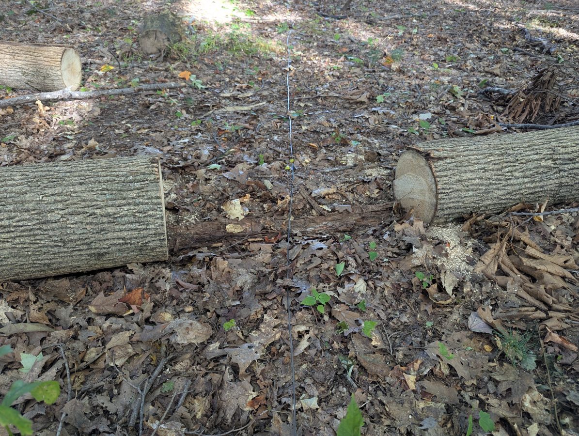
Large Loop On Ground antenna, installed in woods behind my house

I did have to go around and clear away some brush and dead trees along where the antenna wire was laid on the ground. I wanted to make sure that the wire was directly on or within an inch or two of the ground.
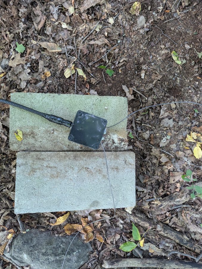
LLOG antenna transformer and transmission line

The transformer took about 20 minutes to construct. It consists of six windings on the antenna side and two windings on the transmission line side. I used a type 73 core because I am more interested in the medium frequency range. It seems to work well up to about 15 MHz. The transformer is for galvanic isolation, keeping the loop current balanced and separated from the transmission line. The shield is not grounded at the antenna side, but is grounded where it comes into the house. On the transformer enclosure, I used a salvaged N connector to match what I had for the transmission line. Any low loss cable, including RG-6 or RG-11 will work very well.
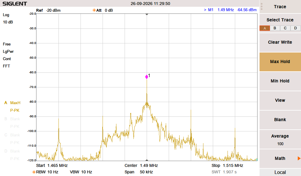
WKNY signal, 18 miles distant from transmitter

After a few hours of low intensity work, I had everything together. I connected the antenna to my trusty Kenwood R-2000 receiver and tuned to the nearest Class C AM on 1,490 KHz. Wow! What a difference! This little 1 KW high band station 18.6 miles (30 km) away barely came in before, especially when the ground is dried out. The relative signal strength meter on the receiver shows an S9+5. I am located on the edge of the predicted 0.5 mV/M contour while the spectrum analyzer shows a -65 dB signal, which is netting a 44 dB SNR, which is very good. All of this is after a Mini Circuits ZSC-4-2 power divider, which has an insertion loss of -6 dB per port.
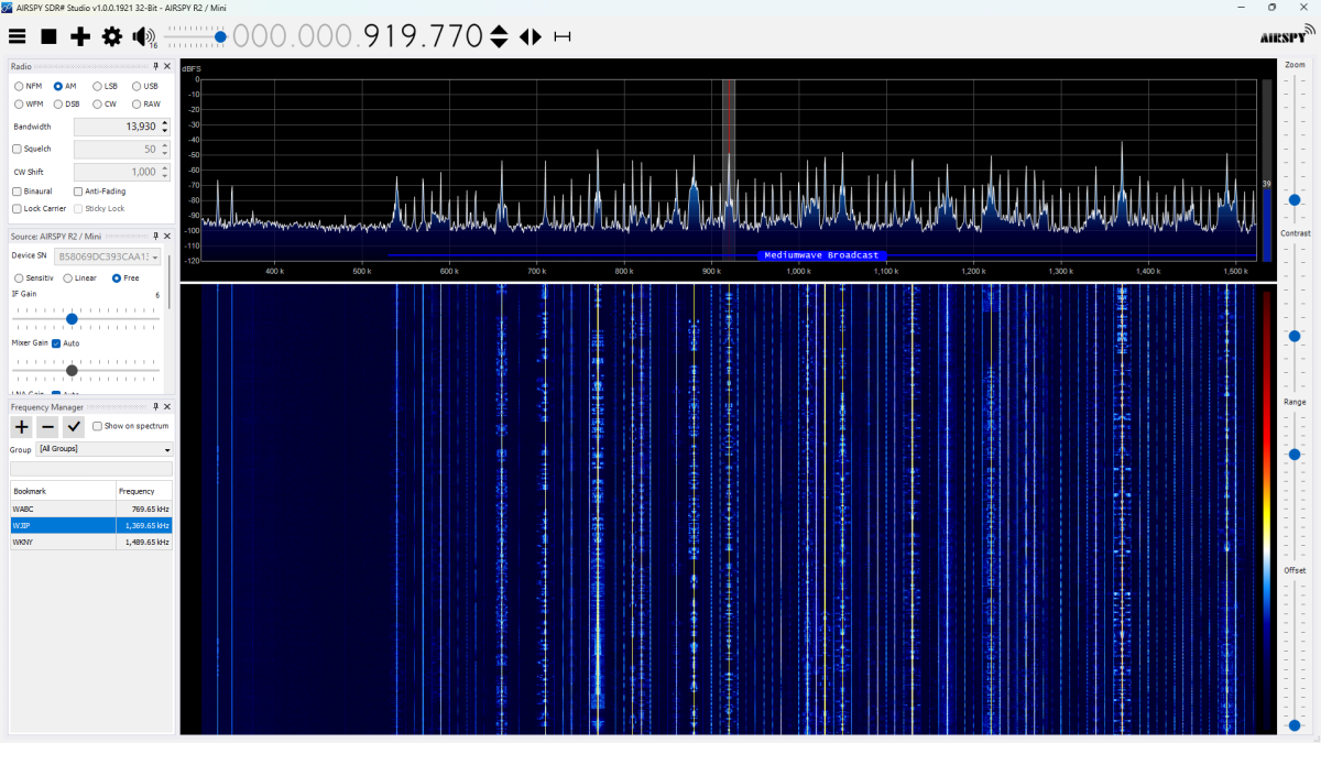
Wide view of the entire AM band, about 1pm

One of the reasons for the “decline of AM;” overcrowding. This was taken during the daytime, when there was no skywave propagation. Barely an open frequency.

With the spectrum analyzer and made a few interesting discoveries. First, the noise floor in the Medium Frequency range goes from about -100 to -110 depending on the frequency. The noise floor on High Frequency is -112 or lower across the entire band. I clearly get all of the NYC AM stations as well as most of the stations in and around Albany. Before sunrise, I tuned around the 630 (472 to 479 KHz) meter band and heard a few stations sending CW (W4TS @ 164 miles (264 KM), K2ORS @ 157.2 miles (253 KM)). A few overnights of WSPR monitoring on 475.6 KHz netted 194 spots from 11 different stations. The furthest was 822 miles (1,322 KM) away in central Illinois. All of these stations are transmitting 5 watts EIRP or less.
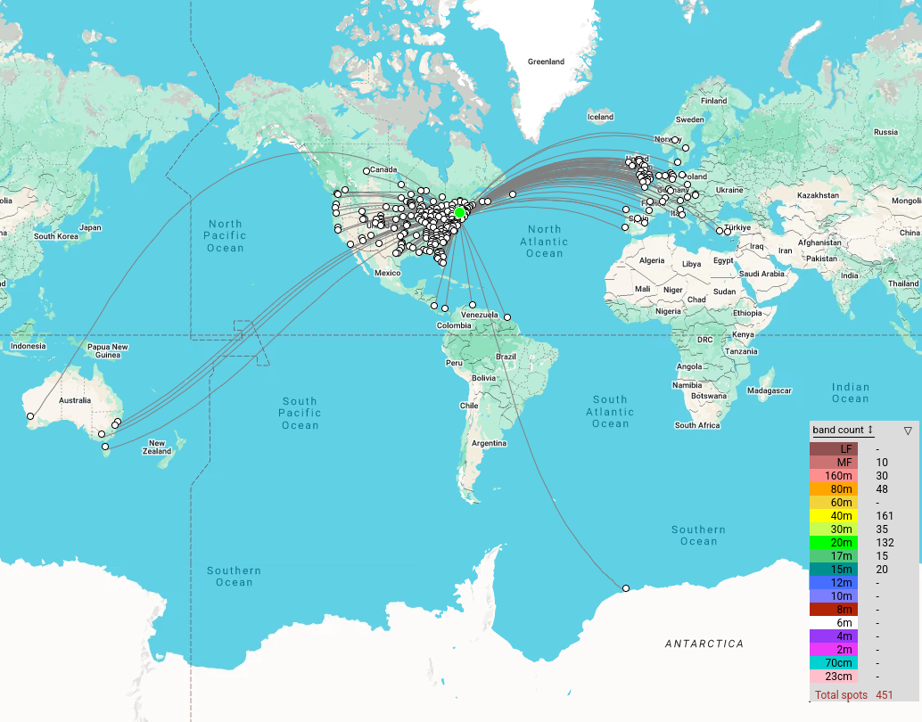
LLOG 72 Hour WSPR reception map

This antenna works well to about 15 MHz, where the signals start to drop off because of the transformer material that I used.

Using the Network Analyzer, I found the resonance is 2.865 MHz with a -36 dB return loss. This makes sense, as the wire laying on the ground will have a lower velocity factor due to the capacitive coupling with the earth. In this case the VF of the antenna is 73% when the soil is dry. The velocity factor should go down when the ground gets wet, or covered with snow.

It might be interesting to do some ground conductivity measurements…

Golos Ameriki

The Voice of America; expended goodwill edition.

Radio Liberty and Radio Free Europe were The main sources of Western information behind the Iron Curtain during the Cold War. While the VOA, RFE, and RL used HF, there were also FM relays in the mix. If you wanted to know what the US Government’s position was on any topic, VOA, RFE, and RL were the information sources.

I wrote several articles about this in the past:

So what happened? Why has the current administration shuttered those services?

There are several good reasons why many government broadcasters have reduced or eliminated shortwave:

  • Fewer people care about the US Government’s position
  • Changes in geopolitics
  • Reduced listenership to HF Shortwave Broadcasts due to technical difficulty
  • Large double-sideband AM transmitters are expensive to operate and maintain and therefore are a target for reducing expenses
  • HF transmitter sites require a lot of land and physical infrastructure, which is also expensive to maintain
  • New distribution technology is easier for the end user and less expensive to operate

Many people, particularly young people, do not know the difference between an over-the-air broadcast and an internet stream. Buying a special receiver, putting up some indoor or outdoor antenna, then tuning around several different frequency bands to find something worth listening to, seems like a lot of work. These days, there are few shortwave broadcasts worth listening to, especially in the English language.

The BBC greatly reduced HF distribution of The World Service starting in 2005, favoring more internet-based distribution. Radio Canada International completely went off the air in 2012, scrapping its extensive transmitter site in Sackville NB in 2014. Radio Australia signed off in 2017. Deutsche Welle mostly left the HF band in 2011 while reducing its FM in 2016. The Voice of Russia ended HF broadcasts in 2014.

The only state-owned shortwave broadcaster that has expanded is Radio China International.

VOA Greenville B has some very old transmitters. The newest units date from the late 1980s or early 1990s. The oldest are the two original Continental 420As, dating from 1960, and are original to the building. When I visited there in 2017, two transmitters were on the air, the BBC and the AEG broadcasting at half power to Cuba and Africa respectively. The rest were shut down. The Continentals were difficult to change frequencies on because of the Doherty modulation. The GEs were long in the tooth, but at least serviceable due to the stock of spare parts from site A. I think the overseas sites in the Philippines and Sao Tome are similar.

Many have pointed out, and rightly so, the Internet censorship issue. Terrestrial radio broadcasting is often the best or only way to circumvent the suppression of information. Kim Elliot pointed this out in his Radio World article “Why we need Shortwave 2.0” All of those points are valid.

What can be done? Implementing DRM30 as a worldwide HF broadcasting standard would be a step in the right direction. DRM30 can send ancillary data, including Radiogram type news bulletins. DRM30 is much more energy efficient than DSB AM because there is no carrier, which wastes half or more of the transmitted power on a carrier that contains no information. Instead of a giant transmitter site, with curtain arrays, a more distributed transmission system with several frequencies on the air at the same time uses lower-powered transmitters, simpler antenna systems such as Rotating Log Period Arrays (RLPA), or non-directional vertical towers. This would require some changes to the FCC rules, but now is the time for that.

TV’s ATSC 1 has something called a “Transport Stream ID,” (TSID) which is a unique number assigned to each broadcaster. Wide-band SDRs are capable of scanning across many HF bands. Implementing something similar for DRM30 HF broadcasts would not be that difficult. Shortwave Listeners just program the HF TSID to lock onto the digital broadcast of their choice, if it is available. This would make HF Broadcasting available to most non-technical people looking for information. Most of this can be done with existing technology. However, DRM still (almost 2 decades later) lacks receivers. There is a development on that front as well: RF2Digital support module. The point is that there are many good ways to improve the technology, keep HF broadcasting relevant, and bypass attempts at internet censorship.

What will be done?

Weak Signal Propagation Reporter

Slightly off-topic, but includes radio.

The antennas are the most interesting aspect of Radio Frequency Engineering to me. The transfer of power in the form of voltage and current to the magnetosphere and back again is where the rubber meets the road. Any opportunity to experiment with the art of antenna design and fabrication is welcome.

This is for the Amateur Radio community. With the upswing of Solar Cycle 25, predicted to peak in July of 2025, I decided it would be fun to get back on the air with some type of HF setup.

My past experience with HF radio and peak solar cycles is that wild fluctuations can occur creating band openings at unusually high frequencies or no propagation at all. The geek in me finds this very interesting. HF Propagation is a complex matter. Long-distance communication can be carried out with very low power levels provided the ionosphere is bouncing signals back to the earth instead of absorbing them.

Weak Signal Propagation Reporter (WSPR) is an HF beacon system, where stations transmit a digital signal containing your call sign and Maidenhead Gird locator for several seconds. The challenge is to have an efficient antenna and use as little power as possible. In this case about 200 mW (0.2 watts) or 23 dBm. The modulation type is MFSK and the bandwidth is 6 Hz. According to Wikipedia, which is mostly accurate about things like this; WSPR uses a transmission protocol called MEPT_JT. That sends messages composed of:

  • 28 bits for callsign, 15 bits for locator, 7 bits for power level, total: 50 bits.
  • Forward error correction (FEC): non-recursive convolutional code with constraint length K = 32, rate r = 1⁄2.
  • Number of binary channel symbols: nsym = (50 + K − 1) × 2 = 162.
  • Keying Rate is 12000 ⁄ 8192 = 1.4648 baud.
  • Modulation is continuous phase 4 FSK, with 1.4648 Hz tone separation.
  • Occupied bandwidth is about 6 Hz.
  • Synchronization is via a 162-bit pseudo-random sync vector.
  • Each channel symbol conveys one sync bit (LSB) and one data bit (MSB).
  • Duration of transmission is 162 × 8192 ⁄ 12000 = 110.6 s.
  • Transmissions nominally start one second into an even UTC minute: e.g., at hh:00:01, hh:02:01, etc.
  • Minimum S/N for reception is around –34 dB on the WSJT scale (2500 Hz reference bandwidth).

Distant stations report reception to a database. Several good websites display reception in a map or table format.

WSPR report

This map shows a good path to coastal Maine on 40 meters. The received signal-to-noise ratio is -2 dB at a distance of 423 KM.

80 Meter End Fed Half Wave antenna supported by trees

My antenna is an End Fed Half Wave (EFHW) cut to 3.568 MHz which can be used on any harmonically related frequency (7, 10, 14, 18, 21, 24, and 28 MHz). To accomplish this, a 49:1 Unun (Unbalanced feed to unbalanced feed) transformer is used to transform the 2,400-ohm impedance of the wire to the 50-ohm impedance required by the transmitter. The antenna works best against a ground system that is not less than 0.05 wavelength or 18 electrical degrees on its lowest frequency. That works out to about 4.2 meters (14 feet). A little bit longer is a little bit better. Six 20-foot long 14 gauge bare copper ground radials are attached to an 8-foot ground rod.

Diecast aluminum box containing 49:1 Unun

The Unun is two FT240-52 (not an affiliate link) cores with 14 gauge enamel wire consisting of 2 turns on the primary and 14 turns on the secondary. The antenna is 40 meters (132 feet) of 10 gauge hard-drawn stranded copper wire. This should be good for about 800 watts CW/SSB on HF if I want to use it in that capacity.

Unun transformer
Unun wire tied to a DIN rail with 100 pF 5 KV capacitor

There are several guides on how to make the unun available via Google search. There is some debate on whether a 64:1 transformer should be used. Most indicate a 49:1 is the best match. The diecast aluminum (not an affiliate link) enclosure is a nice feature. It cost $33.00 on Amazon.

I used the network analyzer to trim up the antenna a bit. I made a few measurements, the first was just the wire with no ground connected. The next was the wire and ground system after trimming the length for resonance on 3.5 MHz.

The transmission line is LMR-400 with N connectors. I loath PL-259s and use N connectors whenever possible.

I did a series of broadband SWR sweeps. The first was just the wire prior to trimming.

First sweep, frequencies are a little low, SWR is a little high

The next was with a ground rod and six ground radials, #14 bare copper wire twenty feet long.

EFHW trimmed up and looks good on everything except 60 Meters (10 MHz)

This demonstrates the effect of a good ground system. It is worth the effort (and it is an effort) to put in some buried ground radials with this type of antenna. I think above-ground radials would work too.

Here is a screenshot of the little Zachtek desktop WSPR beacon transmitter I bought. This is a great addition to the toolbox and works well for testing the radiation efficiency of an HF antenna. It has a GPS antenna input for timing and location reference. The frequency bands are selectable if you are testing a mono-band antenna. It will work into a fairly poor load, so I suggest sweeping the antenna first with an analyzer.

Zachtek configuration web interface
WSPR beacon, 0.2 watts

This shows that my signal is getting out. So far, the furthest distance is 17,030 km with an SNR of -10 (Australia, VK5ARG). That is quite amazing when you think about it. I am letting this run overnight to see how the propagation changes. Overall, this was a good recreational project and now I have a known working HF antenna.

I Audited the RF Noise in my House

The largest problem facing analog AM broadcasting (and digital Medium Frequency and High Frequency broadcasting) is RF Noise.

Like most people, I have many modern conveniences that make my life easier than previous generations; electric lights, central heat and air conditioning, appliances like vacuum cleaners, microwave ovens, and whatnot. I enjoy the wireless internet, have an LED TV, use LED light bulbs, and get free electricity from my photovoltaic solar system. These devices can contribute to the high levels of RF noise found in most buildings. RF Noise which is the bain of AM broadcasting. Digital modulation schemes use variations in amplitude to transmit data bits. They are not immune to RF noise, they simply mask it better until they don’t.

I thought it would be interesting to isolate the various noise generators that may be present.

To make measurements, I used the Siglent SVA-1032X spectrum analyzer. This unit has a noise floor of -140 dB. My methodology is to turn everything off except the Device Under Test. Set the spectrum analyzer up for a wide band sweep, then narrow the bandwidth on any detected noise. Turn the DUT off to make sure that the noise goes away. Turn the DUT back on to make sure that the noise comes back.

The first thing I noticed; there is more noise during the daylight hours than at night. This is interesting. I thought it might be coming from my solar system, which uses individual inverters for each panel (so-called microinverters). These are wired to 240 VAC but have an internet gateway device that is in the house and communicates with the inverters using a power line data scheme. It turns out this was a minor contributor below the AM broadcast band.

By process of elimination, here are things that were not contributing to RF noise on Medium Frequency (AM band):

  • Cable Modem (Motorola MB7420 DOCSIS 3.0)
  • Router/WiFi gateway* (Netgear R6700v2)
  • GB Ethernet Switch (Netgear TLSG116E)
  • Dell Desktop PC’s (three models)
  • Dell Laptop PC (two models)
  • Android phones (two models)*
  • Phillips 4K LED large-screen TV (5PFL5604/F7)
  • LG LED computer monitor (24MK430H-B)
  • Refrigerator (Frigidaire FFTR1835VSD)
  • Stove (GE BP63D W1WH)
  • LG washing machine (WM3400CW)
  • LG clothes dryer (DLEX4501)
  • Bosch dishwasher (SGV68U53UC)
  • Dehumidifier (GE APEL70LTL1)
  • LED light bulbs (Sylvania 9W Ultra LED)
  • Generic incandescent light bulb
  • Furnace (fancy controller)
  • Furnace burner motor**

*These are intentional RF emitters

**The furnace burner motor made a small broadband RF signal on startup, likely the igniter which uses an electric arc. Once the unit was running, there was no further RF emissions noted.

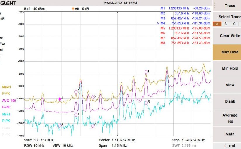
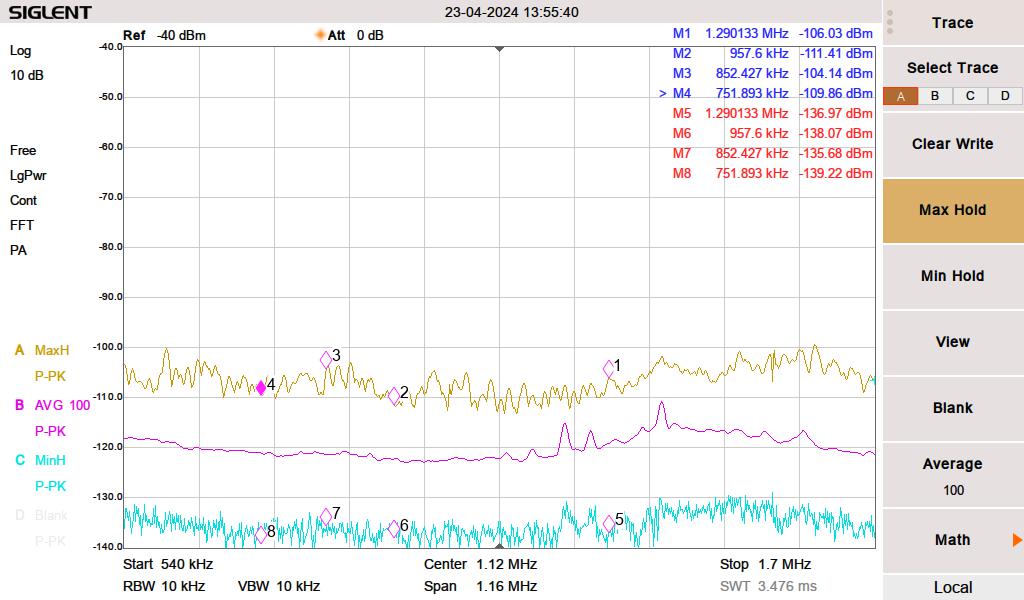
Medium Frequency baseline noise level

The yellow line is the peak hold, the magenta line is the 100 sweep average and the cyan line is the minimum peak hold. I live out in the sticks; there are no streetlights, no stoplights for miles, the nearest cellphone site is four miles away, and houses are spaced far apart.

First, I measured the noise with everything turned off. I then turned things on one by one, noting any changes in the spectrum. For the list noted above, this is the way it looked.

These are a few things contributing to RF noise levels on the MF band.

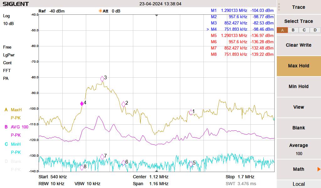
We have cheap Chinese grow lights to start seedlings for our vegetable garden. We were using these during the daytime hours to augment the low sunlight in early spring. I initially thought this was coming from the solar system. The interference was making a massive noise hump between 750 and 957 KHz. The brand of growlight is BestVA B-1000 LED which was purchased from Amazon.

RF noise from Grow Light

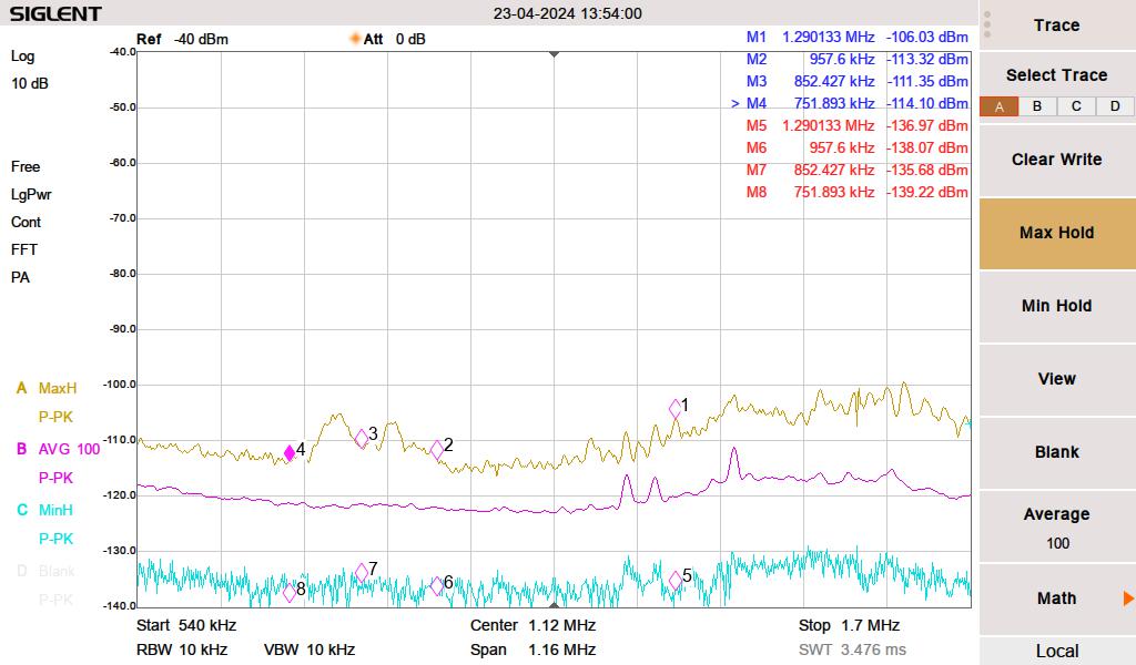
Next, somewhat surprisingly, the LG computer monitor on my desk was creating a pretty decent rise from 1120 KHz to 1700 KHz. I have three LG computer monitors, this is the newest only this one creates any RF noise.

LG 240P500 LED monitor

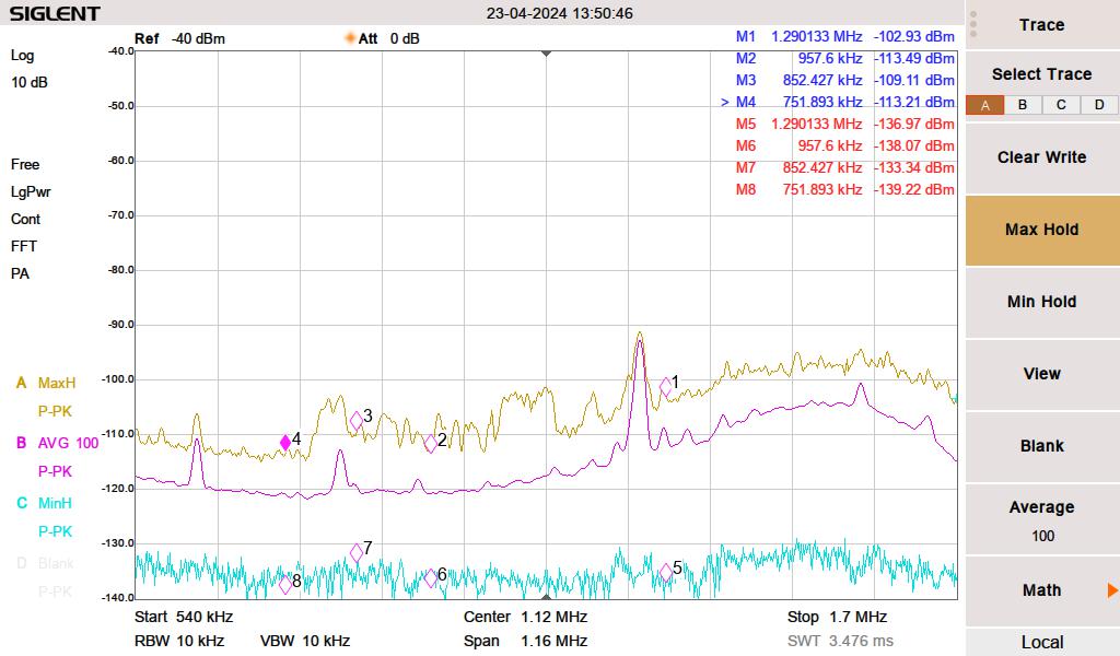
Then, pretty much every florescent lamp (compact or full-length tube) created a broadband noise increase across the entire MF band and well into HF.

Florescent lighting

The vacuum cleaner makes a little bit of broadband RF noise when near the receiver. However, you cannot hear the radio when the vacuum is running, so that does not seem to matter.

None of these are surprising. However, I was more surprised that many other electronic devices are not contributing to RF noise in my house.

A little bit about data over power line or power line communications. Searching for power line data can be a bit tricky. First, there is this large voltage 60 Hz (plus harmonics) waveform to deal with. Secondly, there are many different protocols and many different frequencies. I narrowed down my solar system by listening to my Kenwood R-2000 below 300 KHz. Some noise went away when I completely disconnected the inverters. I don’t know the exact frequency, the protocol, the modulation type, etc. But there is something.

Data Over Power line is popular with home automation systems, it can be used to extend Ethernet LAN, and some power companies are using it to control substation equipment, smart power meters, and/or to function as an ISP for their customers. I have heard some HF users complain about BBPL, but I have not experienced it for myself.