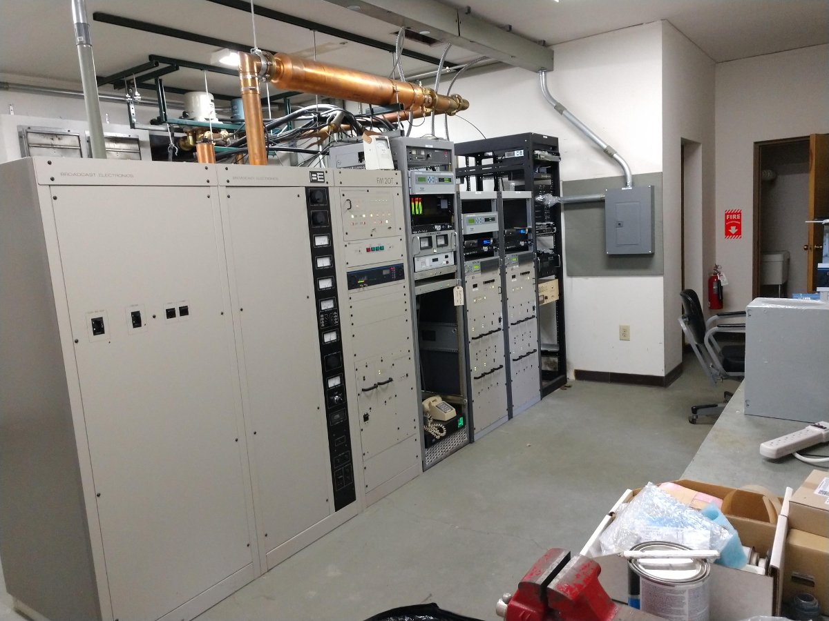
Finishing up a transmitter site rehab. The BE FM20T is nearly 20 years old. The BE FM2C transmitters are new. There is also a rack of new fiber equipment and CODECs. This site has good utilization; there are three stations on one tower with a shared STL antenna and generator.
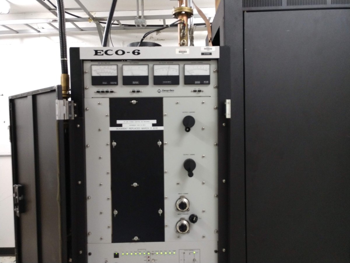
Energy Onix ECO-6
Energy Onix ECO-6 tube-type transmitter. One of Bernie’s better designs; a grounded grid tube with a solid-state driver section. This one needed some fans replaced and a new tube.
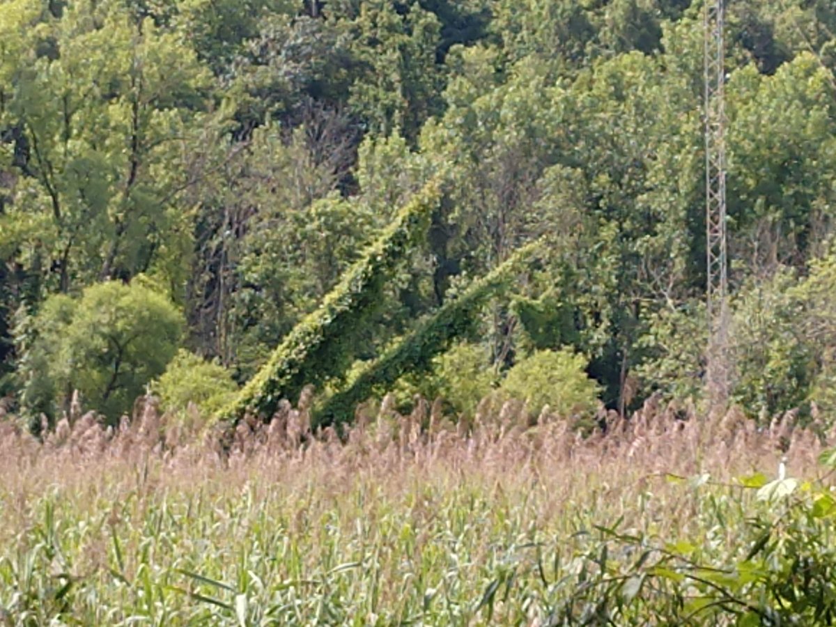
AM transmitter site. Looks like these vines have not been cut in a couple of years.
I wonder how much the guy tensions have changed…
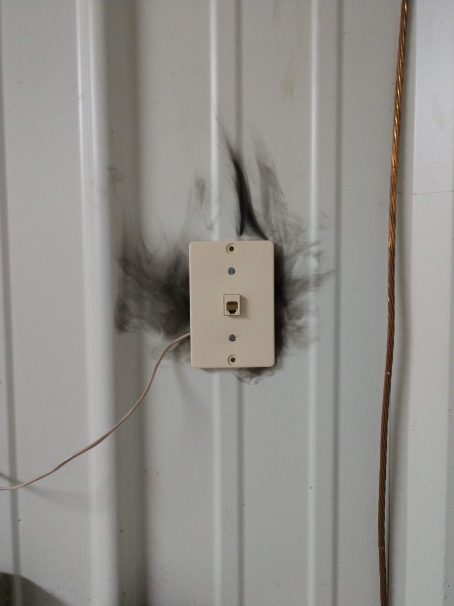
Noticed this after some particularly strong thunderstorms
The reason why you do not use a POTS line phone during a thunderstorm.
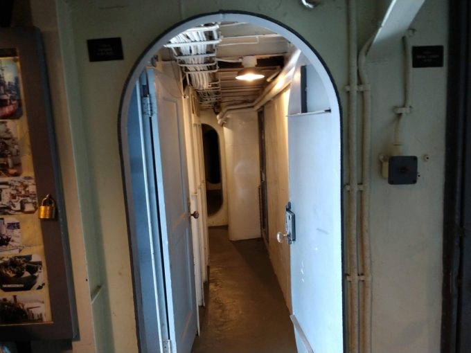
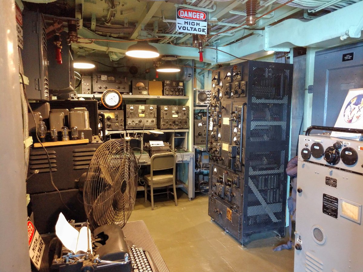
USS Slater radio room
I took a tour of the USS Slater, a museum ship in Albany, NY. The museum has painstakingly restored the ship to its WWII configuration. The main transmitter is the RCA TBL-8 seen in the left/center of this picture. This unit put out 200 to 400 watts CW or 150 watts AM phone. During the hostilities, it was turned off as allied ships observed radio silence unless they were sinking (and sometimes even then).
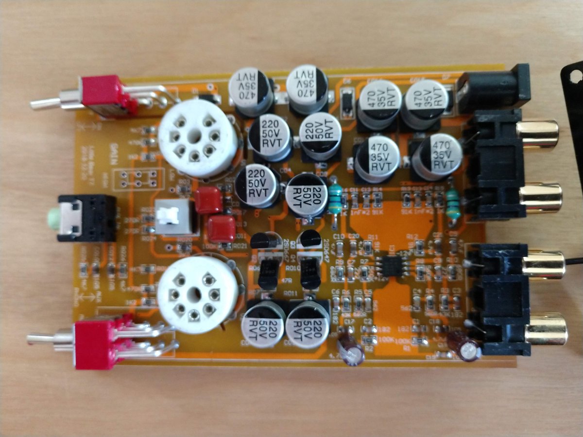
A little ChiFi tube-type RIAA phone preamp.
I have been fooling around with this little 6AK5 preamp. I find it works very well and sounds better than the built-in phone preamp on my Kenwood VR-309. The FU-29 tube amp did not come with a phone preamp.
This is a short video clip of an audio processor at one of our transmitter sites. The fancy lights around the control knob are designed for the program director. They are saying “Buy me… Buy me…”
More and more wireless LAN links are being installed between the transmitter and studio. Often these links are used for network extension, remote control, site security, VOIP telephony, and sometimes even as a main STL. These systems come in several flavors:
Moseley LAN link or similar system. Operates on unlicensed 920 MHz (902-928 MHz) band. Advantages: can use existing 900 MHz STL antennas, can work reliably over longer distances, transmitter, and receiver located indoors. Disadvantages: slow, expensive
ADTRAN TRACER or similar system with indoor transceivers and coax-fed antenna systems. Operates on unlicensed or licensed WLAN frequencies. Advantages: fast, transmitter and receiver located indoors, can be configured for Ethernet or T-1/E-1 ports. Disadvantages; expensive
Ubiquiti Nano bridge or similar system where the transceiver is located in the antenna, the system is connected via category 5/6 cable with POE. Operates on unlicensed or licensed WLAN frequencies. Advantages; fast, relatively inexpensive. Disadvantages; equipment located on the tower, difficult to transition base insulator of series fed AM tower.
Ubiquiti Rocket or similar system where the antenna and transceiver are separate, but the transceiver is often located on the tower behind the antenna and fed with category 5/6 cable with POE. Operates on unlicensed and licensed WLAN frequencies.
For the first two categories of WLAN equipment, standard lightning protection measures are usually adequate:
Good common point ground techniques
Ground the coaxial cable shield at the tower base and at the entrance to the building
Appropriate coaxial-type transmission line surge suppressors
Ferrite toroids on ethernet and power connections
For the second two types of WLAN equipment, special attention is needed with the ethernet cable that goes between the tower and POE injector or switch. Shielded, UV-resistant cable is a requirement. On an AM tower, the shielded cable must also be run inside a metal conduit. Due to the skin effect, the metal conduit will keep most of the RF away from the ethernet cable. Crossing a base insulator of a series excited tower presents a special problem.
The best way to get across the base insulator of a series excited tower is to use fiber. This precludes the use of POE which means that AC power will be needed up on the tower to power the radio and fiber converter. This may not be a huge problem if the tower is lit and the incandescent lighting system can be upgraded to LEDs. A small NEMA 4 enclosure can house the fiber converter and POE injector to run the WLAN radio. Some shorter AM towers are no longer lit.
Another possible method would be to fabricate an RF choke out of copper tubing. This is the same idea as a tower lighting choke or a sample system that uses tower-mounted loops. I would not recommend this for power levels over 10 KW or on towers that are over 160 electrical degrees tall. Basically, some 3/8 or 1/2-inch copper tubing can be wound into a coil through which a shielded ethernet cable can be run. Twenty to twenty-five turns, 12 inches in diameter will work for the upper part of the band. For the lower part, the coil diameter should be 24 inches.
In all cases where CAT 5 or 6 cable is used on a tower, it must be shielded and the properly shielded connectors must be used. In addition, whatever is injecting power into the cable, ether POE injector or POE switch must be very well grounded. The connector on the shielded Cat5 or 6 cable must be properly applied to ensure the shield is grounded.
In addition to that, some type of surge suppressor at the base of the tower is also needed. Tramstector makes several products to protect low voltage data circuits.
Transtector APLU 1101 series data line protector
These units are very well made and designed to mount to a tower leg. They come with clamps and ground conductor designed to bolt to a standard copper ground buss bar.
Transtector APLU 1101 series data line protector
There are various models designed to pass POE or even 90 VDC ring voltage.
Transtector APLU 1101 series data line protector
This model is for POE. The circuit seems to consist mostly of TVS diodes clamping the various data conductors.
As more and more of these systems are installed and become a part of critical infrastructure, more thought needs to be given to lightning protection, redundancy and disaster recovery in the event of equipment failure.
Radio facilities, particularly mountaintop transmitter sites, are prone to power transients. The causes can be varied, but most often, lightning is the culprit. Long power transmission lines to the site are vulnerable to direct strikes and EMF-induced spikes from nearby strikes. Other issues, such as switching transients, load fluctuations, and malfunctioning equipment can lead “clear weather” outages. Of course, the best way to deal with such things is through prevention.
Power line surge suppressors have been around for quite some time. They usually take the form of a MOV (Metal Oxide Varistor) connected between the hot leg and neutral or ground. There are a few differences in designs, however. Typically, most facilities employ a parallel surge suppressor. That normally takes to form of an enclosure hung next to the main power panel with a group of MOV modules in it. The MOVs are fed from a circuit breaker in the panel. Like this:
LEA parallel or shunt surge suppressor
This is an LEA three-phase 208-volt shunt surge suppression unit, which has MOVs between all phases to ground and each other. That is connected in parallel to the electrical service with the circuit breaker disconnect. These function well enough, provided there is a good bit of series inductance before the unit and also, preferably after. The series inductance can come from many sources, including long secondary leads from the utility company transformer or electrical conductors enclosed in metal conduit, particularly rigid (verses EMT, or FMC) metal conduit. The inductance adds a bit of resistance to the transient voltages, which come in higher than 50 or 60 Hz AC waveform.
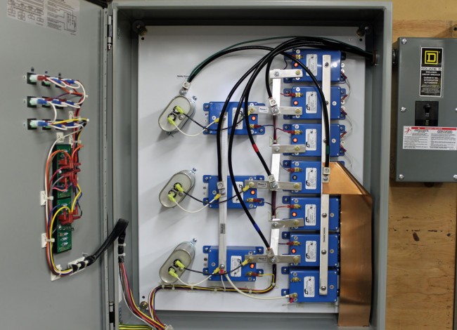
A better method of transient protection is the Series Surge Suppressor. These units are installed in line with the incoming service and include an inductor to add the required series resistance coupled with MOVs and capacitors. Most series surge suppressors also filter out harmonics and RF by design, something desirable, particularly at a transmitter site. Series surge suppressors look like this:
LEA DYNA systems series surge protector
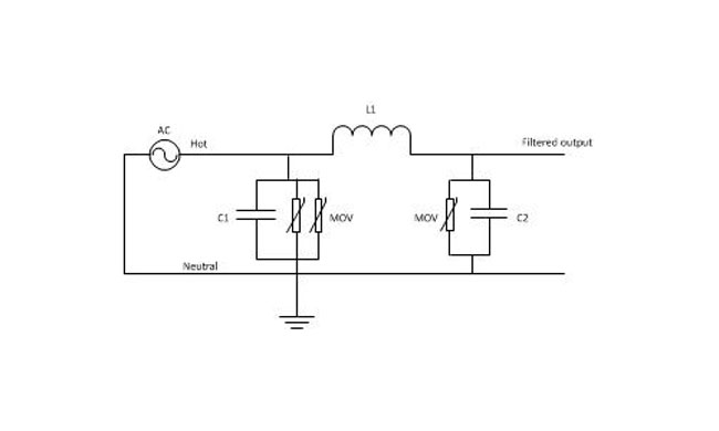
This is an LEA three-phase 240-volt unit. As in the other example, all phases have MOVs to neutral and each other. There are MOVs and capacitors on the line and load side of this unit (the line side is the bottom of the inductor). A basic schematic looks like this:
Series surge suppressor basic schematic
A few things to note; MOVs have a short circuit failure mode and must be fused to protect the incoming line from shorts to the ground. MOVs also deteriorate with age, the more they fire, the lower the breakdown voltage becomes. Eventually, they will begin to conduct current at all times and heat up, thus they should also be thermally fused. MOVs that are not properly protected from overcurrent or over-temperature conditions have the alarming capacity to explode and/or catch on fire. From experience, this is something to be avoided. Matched MOVs can be paralleled to increase current handling capacity.
The inductor is in the 100 µH range, which adds almost no inductive reactance at 60 Hz. However, it becomes more resistive as the frequency goes up. Most transients, especially lightning, happen at many times the 60 Hz fundamental frequency used in power distribution (50 Hz elsewhere unless airborne, then it may be 400 Hz).
Capacitors are in the 1-10 mF range and rated for 1 KV or greater as a safety factor. The net effect of adding capacitance is to create a low-pass filter. Hypothetically speaking, of course, playing around with the capacitance values may net a better lowpass filter. For example, at 100 uH and 5 mF, the cutoff frequency is 225 Hz, or below the fourth harmonic. Care must be taken not to affect or distort the 60 Hz waveform or all sorts of bad things will happen, especially to switching power supplies.
These units also need to have a bypass method installed. If one of the MOV modules needs to be replaced, power to the unit has to be secured. This can be done by connecting it to the AC mains before any generator transfer switch. That way, the main power can be secured and the site can run on generator power while the maintenance on the surge suppression unit is taking place.
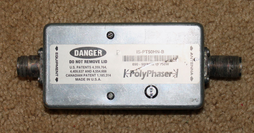
I found this on the floor at an old transmitter site:
Polyphaser IS-PT50HN-B DC block surge suppressor
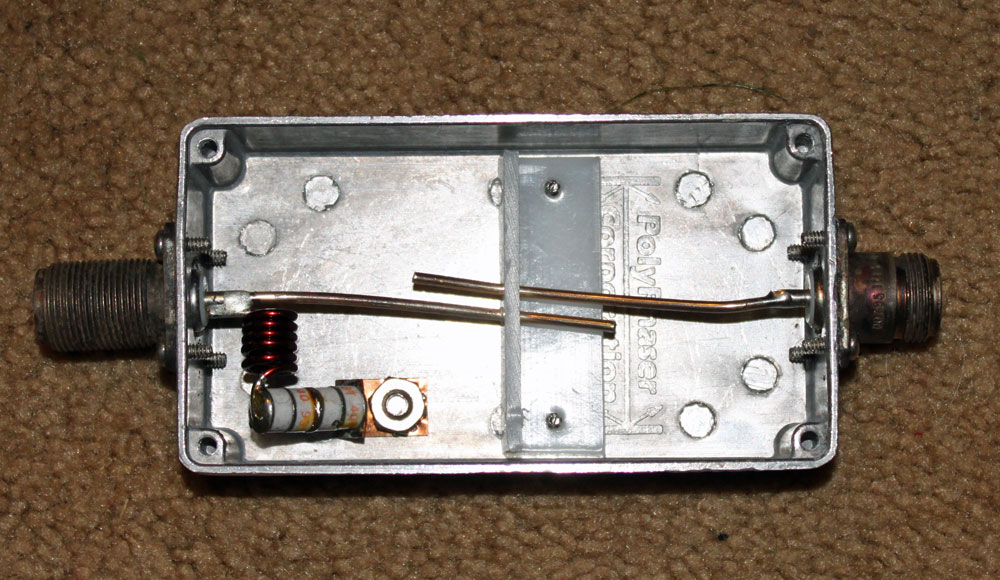
Since it appears to be discarded, I ignored the dire warnings and opened it up to look inside:
Polyphaser IS-PT50HN-B DC block surge suppressor
This is is a DC blocked lightning surge suppressor designed for 890-980 MHz, 750 watts maximum. The two parallel wires represent a capacitor, coupling the radio to the antenna, the inductor acts as an RF block to the gas discharge tubes. The design is such that the inductor acts to block the normal in-use radio frequencies but will allow the 10-30 KHz lightning pulse to pass to the gas discharge tubes and thence to ground. The inductor and gas discharge tubes are on the antenna side of the unit. I measured these units with a DVM and they all appear to be good.
My only comment on this unit is that there is no effort to maintain the transmission line impedance. At the upper end of the UHF spectrum, this can lead to return loss and wasted power. For a receive application, it may not be so bad, but for a transmitter, I would rather use something else.
For lower VHF frequencies, something like this can be DIY fabricated with minimal expense and effort. The case must be bonded to the station ground.