I found this on the floor at an old transmitter site:
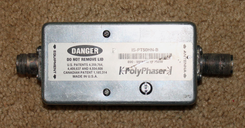
Since it appears to be discarded, I ignored the dire warnings and opened it up to look inside:
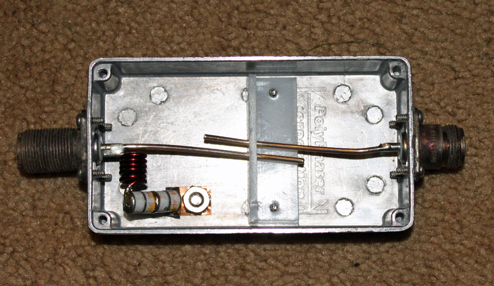
This is is a DC blocked lightning surge suppressor designed for 890-980 MHz, 750 watts maximum. The two parallel wires represent a capacitor, coupling the radio to the antenna, the inductor acts as an RF block to the gas discharge tubes. The design is such that the inductor acts to block the normal in-use radio frequencies but will allow the 10-30 KHz lightning pulse to pass to the gas discharge tubes and thence to ground. The inductor and gas discharge tubes are on the antenna side of the unit. I measured these units with a DVM and they all appear to be good.
My only comment on this unit is that there is no effort to maintain the transmission line impedance. At the upper end of the UHF spectrum, this can lead to return loss and wasted power. For a receive application, it may not be so bad, but for a transmitter, I would rather use something else.
For lower VHF frequencies, something like this can be DIY fabricated with minimal expense and effort. The case must be bonded to the station ground.

The now expired patents, ( e.g http://www.freepatentsonline.com/4359764.html) suggest the designer knew what VSWR is, and set out to create networks that block a surge while incorporating the parasitic capacitance of the surge suppressor with parasitic inductances of surrounding conductors to form an RF passband.
The photographs don’t seem to describe any of the “embodiments” of the marked patents, but the labeling suggests the inventor regarded the same principle as being used. Discontinuities in transmission line structures and short, grossly mismatched sections can be used to simulate lumped inductances, but I’d never seen one like this.
Here’s the abstract of the first patent.
A connector is provided for the suppression of electromagnetic impulses traveling a radio frequency cable. Paired first and second electrical connectors are provided for being operatively interposed along the signal cable. A spacer or mounting device is provided for electrically coupling the primary conductors and secondary conductors of one connector to their counterparts in the other paired connector. A gas discharge tube having a known breakdown voltage and a known capacitance is electrically and mechanically coupled between the first and second conductors of the mounting device. The inductance of the elements comprising the mounting device are determined such that this inductance interacts with the capacitance of the gas discharge tube and other stray capacitance of the combination thereof in order to produce a characteristic impedance which is generally equal to the characteristic impedance of the radio frequency signal cable, whereby the supressor will dissipate electrical surges while representing a low standing wave ratio to radio frequency energy being transmitted along the radio frequency signal cable.
Dave, that is interesting. Roger Block designed many of Polyphaser’s equipment early on. I will have to break out the network analyzer and see that the actual impedance and return loss is through this piece of equipment. If it matches the theories in the patent, then it is a very cleaver design.
I hate when people throw RF parts out like that. Unless its fried to a crisp, there is a use for some of it, somewhere.
Sometimes it’s because the site had taken a confirmed hit, and a batch replacement of ALL protection equipment is warranted. Or the gas module there may have shorted or gone completely open.