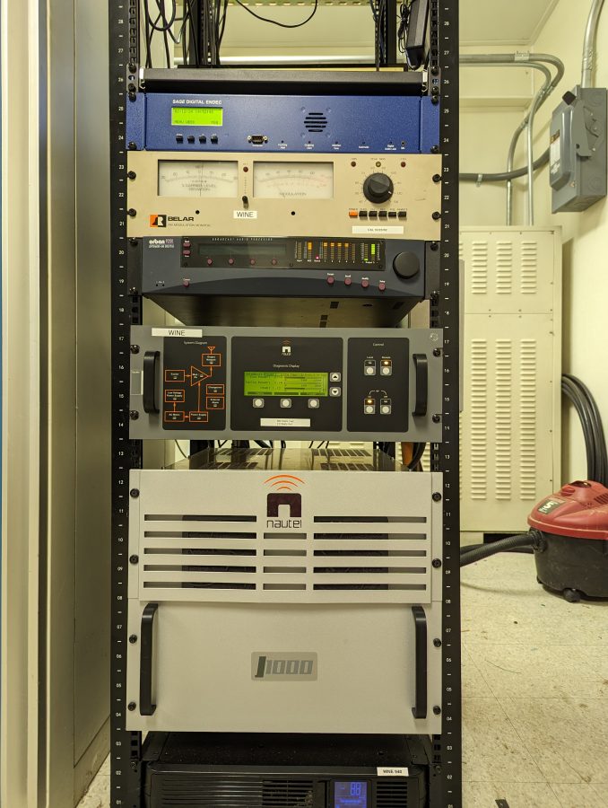
I Finished up this installation of a J-1000 in Brookfield, Connecticut for Nossa Radio. That is a Portuguese broadcaster that owns three other stations in the US.
WINE 940 KHz Brookfield, CT
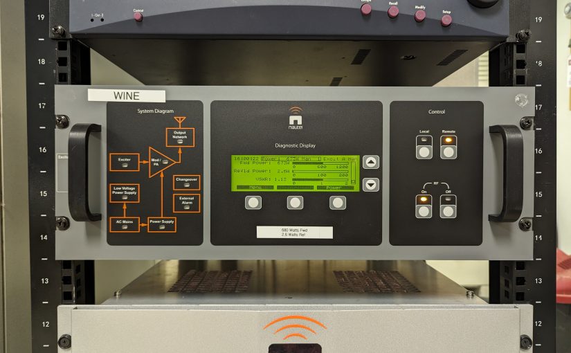
These Nautels are fairly simple affairs; a controller and two RF amps with incumbent power supplies.
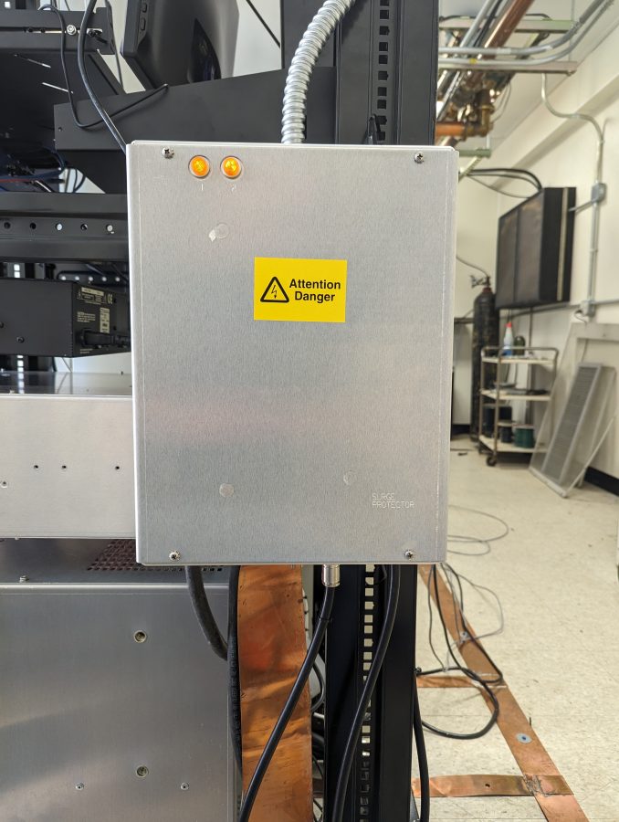
Nautel AM-RF and AC mains surge suppressor
Be sure to install the surge suppressor that comes with the transmitter.
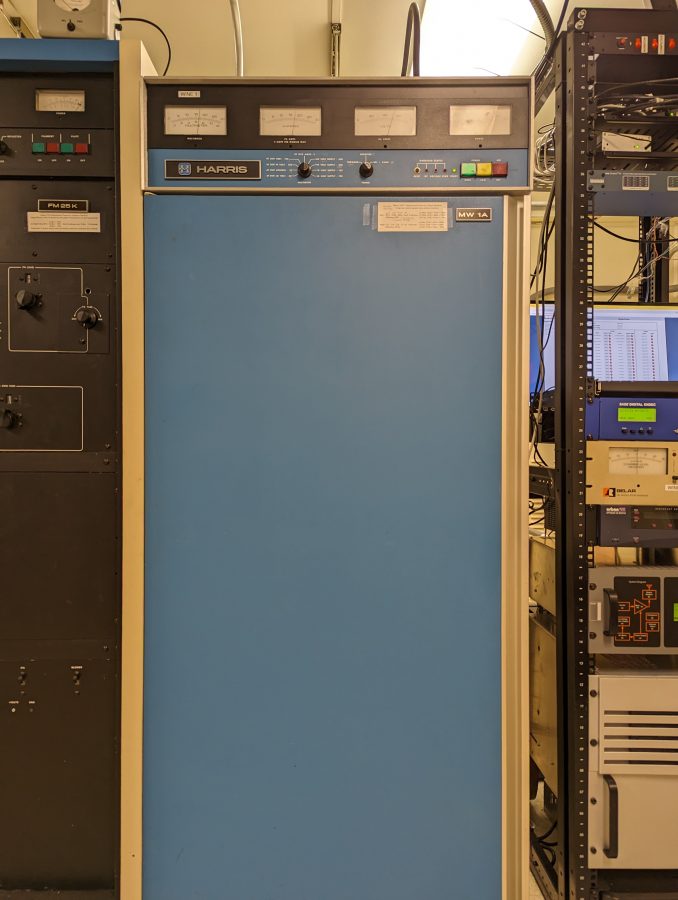
The J-1000 is replacing the 43-year-old Harris MW-1A which will function as a backup. Like all new transmitter installations; some things must be done to complete the job.
Harris MW1A
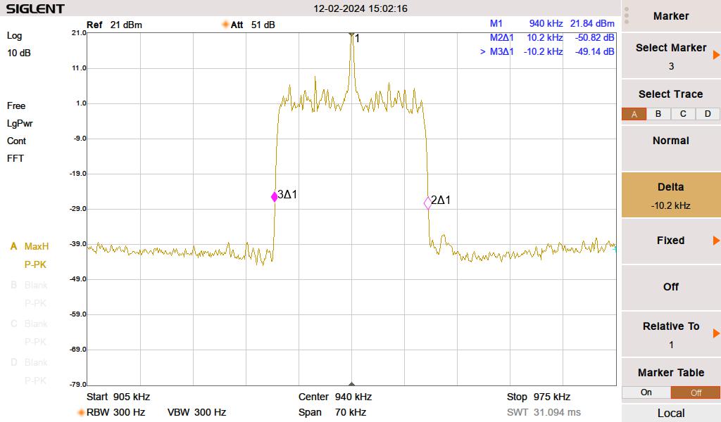
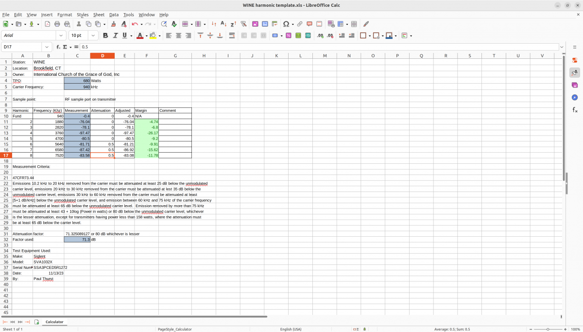
Harmonic measurements out to about the 5th or 6th harmonic need to be documented and compliant with NRSC-2 (AM mask requirements). Although NRSC-2 measurements are required, I don’t see how they can enforce that specification after AM HD radio came into being. Nevertheless, it was measured and passed. With the station carrier power of 680 watts, I used the RF monitor port on the back of the transmitter to make the measurement. Otherwise, I would need to find an empty field somewhere 1 KM away and stand in the middle of it to reduce all of the electrical noise.
Spectrum Mask from a Spectrum Analyzer
The NRSC-2 mask is mainly a function of High-Frequency limitation in the audio processor—certain transmitters, like the aforementioned MW1A did make some contributions to out-of-tolerance measurements.
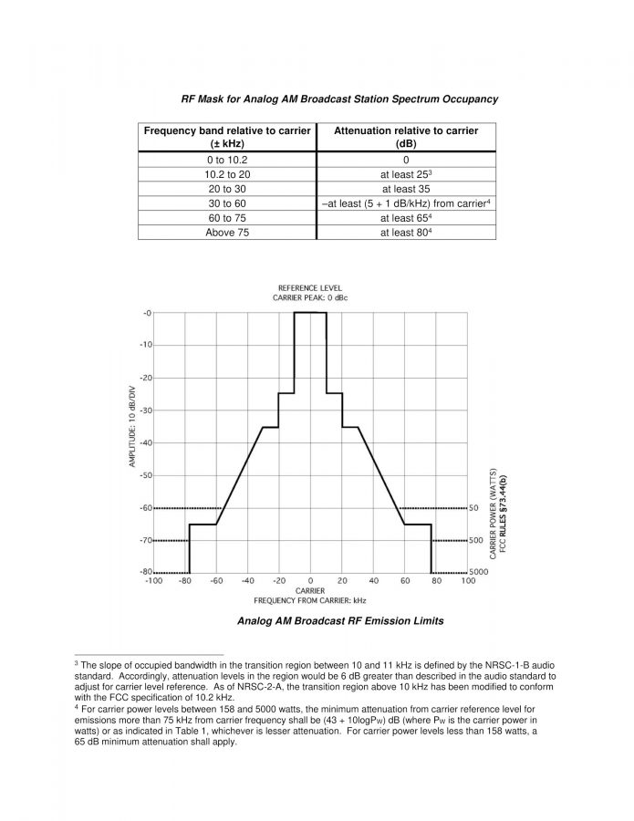
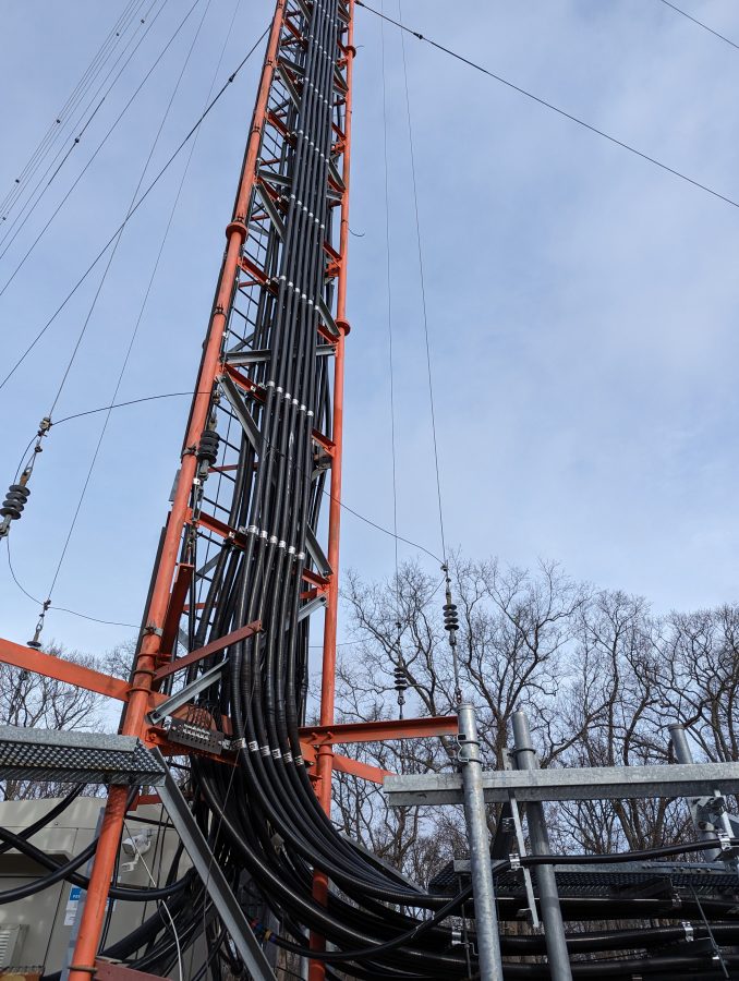
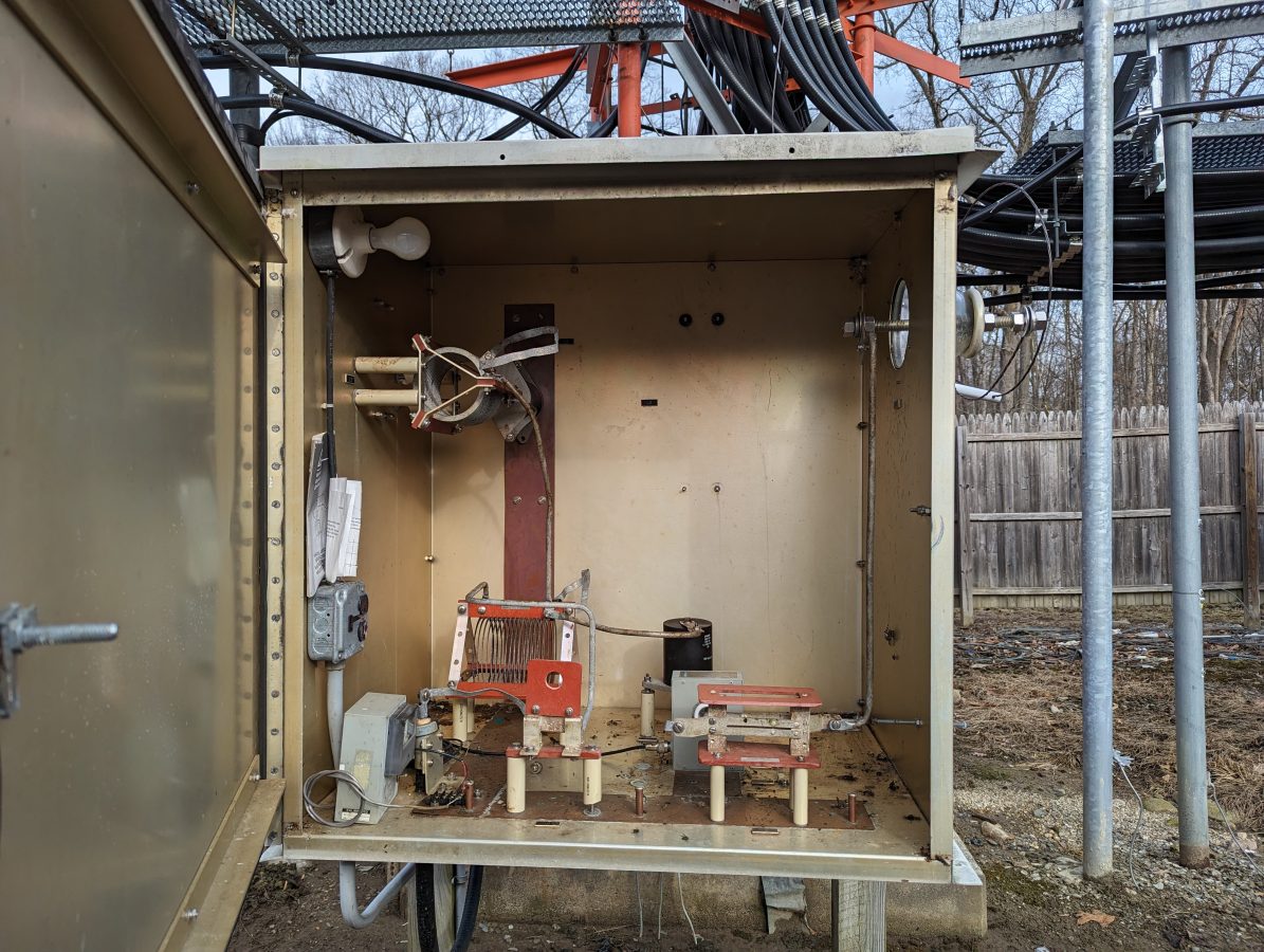
NRSC-2C AM mask requirementsHarmonics measurementsWINE folded unipole feed point
The antenna is a skirted tower that has many other services colocated on it. At the top is WRKI.
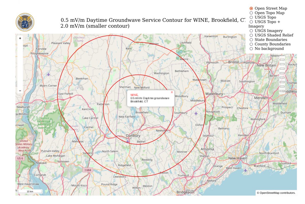
WINE ATUWINE daytime coverage map
Driving away from this site, I would have to agree with the predicted contour map above, at least on the highway. I think it may be a bit different driving around in town.
I have been tasked with fixing one of these glorious contraptions. Aside from the usual Energy Onix quirks; design changes not reflected in the schematic diagram and a company that no longer exists, it seems to fairly simple machine. Unfortunately, it has spent its life in less-than-ideal operating conditions.
Energy Onix Pulsar 1000 in the wild. Excuse the potato-quality photo
Upon arrival, it was dead in the water. Found copious mouse droppings, dirt, and other detritus within and without the transmitter. Repaired the broken start/stop switches, fixed the RF drive detector, replaced the power supply capacitors, and now at least the unit runs. The problem now is the power control is unstable. The unit comes up at full power when it is first switched on, then it drops back to 40 watts, then after it warms up more goes to about 400 watts and the audio sounds distorted. This all points towards some type of thermal issue with one of the power control op-amps or another composite device.
After studying the not-always-accurate schematic diagrams, the source of the problem seems to be the carrier-level control circuit. This is based around a Fairchild RC4200AN (U10 on the Audio/PDM driver board) which is an analog multiplier chip. That chip sets the level of the PDM audio output which is fed into the PDM integrator circuit. Of course, that chip is no longer manufactured. I can order one from China on eBay and perhaps that will work out okay. This all brings to mind the life cycle of solid-state components. One problem with the new technology; most solid-state components have a short production life, especially things like multiplier chips. Transmitters are generally expected to last 15-20 years in primary service. Thus, transmitter manufacturers need to use chips that will not become obsolete (good luck with that), or purchase and maintain a large stock of spare parts.
In the meantime, the chip is on its way from China. Truth be told, this fellow would be better off with a new transmitter.
I was at a transmitter site a few days ago scrapping a Continental 814-R1 transmitter. I started thinking (always a dangerous thing) about how many of these units I have decommissioned over the years. It turns out, quite a few:
Make/Model
Year new*
Year removed
Station
Disposition
GE BT25A
1948
1994
WPTR
Donated/scrapped
Gates BC5P
1960
2004
WWLO
Donated
Harris MW5A
1982
2000
WLNA
Scrapped
Gates BC1T
1961
2001
WLNA
Donated
Harris FM20H3
1972
2001
WYJB
Scrapped
RCA BT1AR
1960
2001
WROW
Donated
Harris BC1G
1972
2001
WDFL
Abandoned
Harris FM20H3
1971
2005
WHUD
Scrapped
BE FM30A
1988
2005
WHUD
Cannibalized
Harris FM5G
1972
2008
WSPK
Scrapped
Mc Martin BF3.5K
1976
2011
WCTW
Scrapped
RCA BTF-10ES
1978
2011
WRKI
Scrapped
Gates BC1T
1964
2011
WINE
Scrapped
Continental 315F-R1
1985
2013
WVMT
Donated
Collins 813F
1975
2014
WKXZ
Scrapped
RCA BTA1AR
1965
2014
WCHN
Scrapped
Collins 813F2
1978
2015
WKXZ
Scrapped
Collins 830D-1A
1968
2014
WKXZ
Scrapped
Harris FM20H3
1972
2013
WYJB
Scrapped
Harris BC5HA
1973
2013
WROW
Scrapped
Harris FM10H
1971
2013
WMHT-FM
Scrapped
Harris FM2.5H3
1973
2015
WEXT
Scrapped
Mc Martin BF3.5K
1972
2014
WSRK
Scrapped
CCA FM5000G
1980
2015
WTBD
Scrapped
RCA BTF1E
1972
2016
WZOZ
Scrapped
QEI 695T3.5
1996
2015
WBPM
Scrapped
QEI 695T5
1996
2015
WBPM
Scrapped
Harris HT3.5
1997
2015
WUPE-FM
Scrapped
Harris Z5CD
1997
2015
WXPK
Cannibalized
Energy Onix SSA1000
2000
2015
WDHI
Cannibalized
Harris MW1
1982
2016
WPUT
Abandoned
Mc Martin BF1K
1982
2016
WSUL
Scrapped
Mc Martin BF3.5K
1982
2016
WSUL
Scrapped
Continental 814R1
1980
2016
WDBY
Scrapped
Broadcast Electronics FM35A
1986
2017
WEBE
Cannibalized
CCA FM-1000D8
1973
2018
WDLA
Scrapped
Collins 828E
1978
2018
WSYB
Scrapped
Gates BC-1H
1971
2018
WHUC
Scrapped
Gates BC-1J
1954
2019
WBEC
Scrapped
Gates BC250GY
1969
2019
WSBS
Scrapped
Nautel V-7.5
2009
2021
WSPK
Cannibalized
Nautel V-10
2007
2023
WHUD
Cannibalized
Nautel V-10
2007
2023
WHUD
Cannibalized
Harris FM1H3
1970
2024
WBEC-FM
Scrapped
Thales TD2U
2005
2025
WPNI-DT
Scrapped
Harris MW1A
1983
2025
WKIP
Cannibalized
*In some cases the “Year New” is a guess based on when the station went on the air. Before you write me and say “But model XYZ transmitter wasn’t made until 19XX, I did not look at every nameplate and write all the information down as I did this.
RCA BTA-10U AM transmitter
First, if the transmitter was made before 1978, the possibility of PCB capacitors and transformers exists. In the case of the GE BT25A, massive amounts of PCBs needed to be disposed of properly. According to current federal laws, ownership of PCBs and PCB-contaminated items cannot be transferred. Thus, the transformer casings were cleaned and taken to Buffalo to be buried in a PCB-certified landfill. Otherwise, most other transmitters, such as the RCA BTA-10, may have a few PCB capacitors and perhaps the modulation transformer. Those items can be disposed of by calling an authorized environmental disposal company like Clean Harbors.
The rest of the transmitter is stripped of any useful parts. Things like vacuum variable capacitors, rectifier stacks, blower motors (if they are in good condition), HV power supply contactors, unique tuning parts, whole control and metering boards, tube sockets, etc.
The remaining carcass is then disassembled and hauled off. I have a guy that will do this for relatively little money. He takes the transmitter back to his warehouse cuts it up, sorts the various metals out, and then takes it to the scrap yard. This includes cutting all the windings off of transformers and power supply chokes, sorting out the brass and copper tuning parts, etc. Thus, most of the transmitter is recycled. Things like vacuum tubes, circuit boards, and other plastic parts are disposed of as e-waste.
This saddens me a little bit. Apparently, the Village of Valatie, NY is seeking repayment of a $500K loan from Transmitter Manufacturer Energy Onix. Since the passing of Bernie Wise, the company has basically folded.
The village may foreclose on the building if necessary, said Mayor Diane Argyle.
Located at 1306 River St., Energy-Onix was founded in 1987 by broadcast pioneer Bernard Wise, who is known for bringing the “grounded grid” to radio broadcasting. The company designed, manufactured and sold radio transmitters and tubes.
Sadly, there goes support for many Energy Onix and CCA transmitters still in the field. I know of several of those old CCA transmitters that are still cranking away, 40 or more years after they rolled out of the factory in Gloucester, NJ. I have tried, several times, to call Energy Onix since Bernie passed last year and the phone goes unanswered. I wonder if we could pick up the field support and service for these units. I wonder if there are any spare parts left at the old factory building?