Engineering Radio: The Oh Dear God Edition.
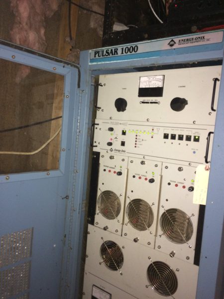
I have been tasked with fixing one of these glorious contraptions. Aside from the usual Energy Onix quirks; design changes not reflected in the schematic diagram and a company that no longer exists, it seems to fairly simple machine. Unfortunately, it has spent its life in less-than-ideal operating conditions.

Upon arrival, it was dead in the water. Found copious mouse droppings, dirt, and other detritus within and without the transmitter. Repaired the broken start/stop switches, fixed the RF drive detector, replaced the power supply capacitors, and now at least the unit runs. The problem now is the power control is unstable. The unit comes up at full power when it is first switched on, then it drops back to 40 watts, then after it warms up more goes to about 400 watts and the audio sounds distorted. This all points towards some type of thermal issue with one of the power control op-amps or another composite device.
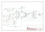
After studying the not-always-accurate schematic diagrams, the source of the problem seems to be the carrier-level control circuit. This is based around a Fairchild RC4200AN (U10 on the Audio/PDM driver board) which is an analog multiplier chip. That chip sets the level of the PDM audio output which is fed into the PDM integrator circuit. Of course, that chip is no longer manufactured. I can order one from China on eBay and perhaps that will work out okay. This all brings to mind the life cycle of solid-state components. One problem with the new technology; most solid-state components have a short production life, especially things like multiplier chips. Transmitters are generally expected to last 15-20 years in primary service. Thus, transmitter manufacturers need to use chips that will not become obsolete (good luck with that), or purchase and maintain a large stock of spare parts.
In the meantime, the chip is on its way from China. Truth be told, this fellow would be better off with a new transmitter.


I had a similar situation about three years ago. You tell the owner that the company is no longer in business, there are no parts readily available and the transmitter needs to be replaced. The guy I was working with understood and a brand new Nautel was ordered post haste. That and some quick antenna matching had that owner thinking I hung the moon, he paid me in full before I left after installing the new Nautel! The down side to this situation with the EO is you will get it back up and running THIS time and the owner/GM will expect you to be able to pull a rabbit out of your hat EVERY time it goes down from here on out.
AM in Boise has been off the air since June 24th. They have a Pulsar 5. Meanwhile, their translator plays merrily on.
This guy’s a mini- Brian Dodge.
“I have been tasked with fixing one of these glorious contraptions.”
Having BTDT, all I can say is I’m sorry. 😛
I’m fighting the same issues with a different brand- Omnitronix.
those “world standard” “easily obtainable” parts have a production lifespan much shorter than the transmitter itself.
It should probably be standard practice to purchase a 100% semiconductor spares kit when any solid state transmitter is installed and put it away somewhere. Often can be done for not much money. Of course needing time machines and all at this point.
If you want another one to play with… email me… I have one the works to about 250 w….
Well… if you are giving it away, it might be a fun project
Paul… I
I thought I had one to give you…
But I think it has the same problems yours has. Like you I just got it dropped in my shop (again) to be repaired.
I can get this one to 250 W with the power control full on. I haven’t got into it enough to see if the power supplies are down or PA transistors are bad but, it passes distorted audio… Contact me as I could use a little help. This is the first one I’ve seen. I have a couple of places to start but, like you I’d like to finish it ASAP.
We can fix all of Bernie’s boxes, and source parts and can provide some tech support on the phone. Contact me if we can help.
Mike Patton
Michael Patton & Assoc
225-266-9745 cell
I’ve been keeping one of these Pulsar 1000s on the air since 2013. So far it’s been power mosfets going out. Good think they are cheap! I’ve put in lots of them. Currently have a problem with power module No. 2. New mosfets don’t seem to fix the problem!
The RC4200 was used in some of the nautel transmitters too, including the J1000. I imagine you could get one from them.
Besides the more common overdrive, underdrive, lightning and transient problems, there is another factor for repeated Mosfet failure. I dealt with a Harris SX-5 that kept burning out Mosfets, and after doing a complete re-tune of the transmitter final in 2011, the problems completely stopped. The transistors are both resistive and reactive and must be exactly matched to the transmitter final circuit. You need an Oscilloscope, a Vector Network Analyzer, factory data, and experience to do this. But the failures can be stopped. A Harris Gates One that I re-tuned in 1998 has only lost one transistor. Address any RF drive, transient suppression or grounding issues first before looking at the tuning. There is no telling how many transmitters have been scrapped for lack of proper tuning of the final.
I just got one of those I just got I think I can make it work I have been a radio engineer for 30 plus year’s and take care of a radio station in pampa tx my home town but work I Amarillo TX as a electronics technician at a TV repair shop also work on broadcast equipment here as well also take care of some radio stations here as well also I have been keeping a old gates 1971 model am going lost the plate supply a year ago was no longer available so I used two microwave oven transformers to get it working again and works great but I know that it’s days are numbered if you like you can text me at XXX-XXX-XXXX (redacted).
With the DX series Harris figured out another failure mode with the FETs. When the RF is muted the decaying RF envelope starts dropping in frequency and becomes out of phase with the drive on the gates and the output of the FET then “POP” goes the FET.
“A.4.8 Oscillator Sync
“Oscillator Sync” synchronizes theRF drive phase to any ringing currents in the combiner/output network during VSWR protection.
The circuit replaces the oscillator signal with a current sample from the output network. The oscillator sync is adjusted with DIP switch S1 and inductor L4.
The Output Current sample from T6 at the combiner output is brought into the Oscillator at J3-1. Resistor R37 provides a
50-ohm input impedance, and zener diodes CR11 and CR12
protect Q4 from transient voltages. The signal phase is adjusted by DIP-switch selected capacitors C30 through C33 and L4. The signal is converted to TTL level by Q4 and fed to CMOS analog switch U4-11.
During normal operation, the Oscillator signal is routed through U4 to buffer-driver U3 and then to the Buffer Amplifier. During VSWR protection (and RF MUTE) a logic HIGH signal from the LED Board turns on Q5 and switches U4 so that the output current sample is used as the transmitter’s RF drive.
Do you still work on these. I have a 3 power levels amp. No books on it.