In the progression from Circuit Switched Data to Packet Switched Data, I can think of many different applications for something like this:
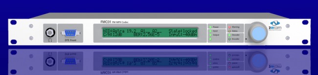
FMC01 MPX to IP CODEC
The FMC01 MPX to IP encoder can be used for multi-point distribution (multi-frequency or same-frequency network) of FM Composite audio, or as a backup solution over a LAN bridge, LAN extension, or public network. I can think of several advantages of using this for a backup when composite analog STLs are in use. There are many compelling reasons to extend the LAN to the transmitter site these days; Transmitter control and monitoring, security cameras, office phone system extensions, internet access, backup audio, etc. I would think, any type of critical infrastructure (e.g. STL) over a wireless IP LAN extension should be over a licensed system. In the United States, the 3.6 GHz WLAN (802.11y) requires coordination and licensing, however, the way the rules are set up, the licensing process is greatly simplified over FCC Part 74 or 101 applications.
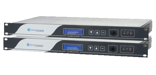
Another similar CODEC is the Sigmacom Broadcast EtherMPX.
Sigmacom Broadcast EtherMPX CODEC
Features include: • Transparent Analog or Digital MPX (MPX over AES), or two discrete L/R channels (analog or AES). • Built-in MPX SFN support with PTP sync (up to 6.000km in the basic version). No GPS receivers! • Unicast or Multicast operation to feed an unlimited number of FM transmitters with MPX from one encoder. • Linear uncompressed PCM 24-bit audio. • Very low audio latency: 2,5mS in MPX mode. • Perfect match with Sigmacom DDS-30 Exciter with Digital MPX input. • Can be used with high-quality 802.11a/n Ethernet links. • DC coupled, balanced Analog inputs & outputs with -130dBc noise floor. • No modulation overshoots due to compression or AC capacitor coupling. • Decoder provides simultaneous Analog & Digital output for transmitter redundancy. • Aux RS232 serial transparent link, Studio to Transmitter. • Auto switchover to Analog input when Digital signal is lost. • Centralized remote control & management software
One last thought; separating the CODEC from the radio seems to be a good idea. It allows for greater flexibility and redundancy. Using an MPX-type STL allows sensitive air chain processing equipment to be installed at the studio instead of the transmitter site.
More and more wireless LAN links are being installed between the transmitter and studio. Often these links are used for network extension, remote control, site security, VOIP telephony, and sometimes even as a main STL. These systems come in several flavors:
Moseley LAN link or similar system. Operates on unlicensed 920 MHz (902-928 MHz) band. Advantages: can use existing 900 MHz STL antennas, can work reliably over longer distances, transmitter, and receiver located indoors. Disadvantages: slow, expensive
ADTRAN TRACER or similar system with indoor transceivers and coax-fed antenna systems. Operates on unlicensed or licensed WLAN frequencies. Advantages: fast, transmitter and receiver located indoors, can be configured for Ethernet or T-1/E-1 ports. Disadvantages; expensive
Ubiquiti Nano bridge or similar system where the transceiver is located in the antenna, the system is connected via category 5/6 cable with POE. Operates on unlicensed or licensed WLAN frequencies. Advantages; fast, relatively inexpensive. Disadvantages; equipment located on the tower, difficult to transition base insulator of series fed AM tower.
Ubiquiti Rocket or similar system where the antenna and transceiver are separate, but the transceiver is often located on the tower behind the antenna and fed with category 5/6 cable with POE. Operates on unlicensed and licensed WLAN frequencies.
For the first two categories of WLAN equipment, standard lightning protection measures are usually adequate:
Good common point ground techniques
Ground the coaxial cable shield at the tower base and at the entrance to the building
Appropriate coaxial-type transmission line surge suppressors
Ferrite toroids on ethernet and power connections
For the second two types of WLAN equipment, special attention is needed with the ethernet cable that goes between the tower and POE injector or switch. Shielded, UV-resistant cable is a requirement. On an AM tower, the shielded cable must also be run inside a metal conduit. Due to the skin effect, the metal conduit will keep most of the RF away from the ethernet cable. Crossing a base insulator of a series excited tower presents a special problem.
The best way to get across the base insulator of a series excited tower is to use fiber. This precludes the use of POE which means that AC power will be needed up on the tower to power the radio and fiber converter. This may not be a huge problem if the tower is lit and the incandescent lighting system can be upgraded to LEDs. A small NEMA 4 enclosure can house the fiber converter and POE injector to run the WLAN radio. Some shorter AM towers are no longer lit.
Another possible method would be to fabricate an RF choke out of copper tubing. This is the same idea as a tower lighting choke or a sample system that uses tower-mounted loops. I would not recommend this for power levels over 10 KW or on towers that are over 160 electrical degrees tall. Basically, some 3/8 or 1/2-inch copper tubing can be wound into a coil through which a shielded ethernet cable can be run. Twenty to twenty-five turns, 12 inches in diameter will work for the upper part of the band. For the lower part, the coil diameter should be 24 inches.
In all cases where CAT 5 or 6 cable is used on a tower, it must be shielded and the properly shielded connectors must be used. In addition, whatever is injecting power into the cable, ether POE injector or POE switch must be very well grounded. The connector on the shielded Cat5 or 6 cable must be properly applied to ensure the shield is grounded.
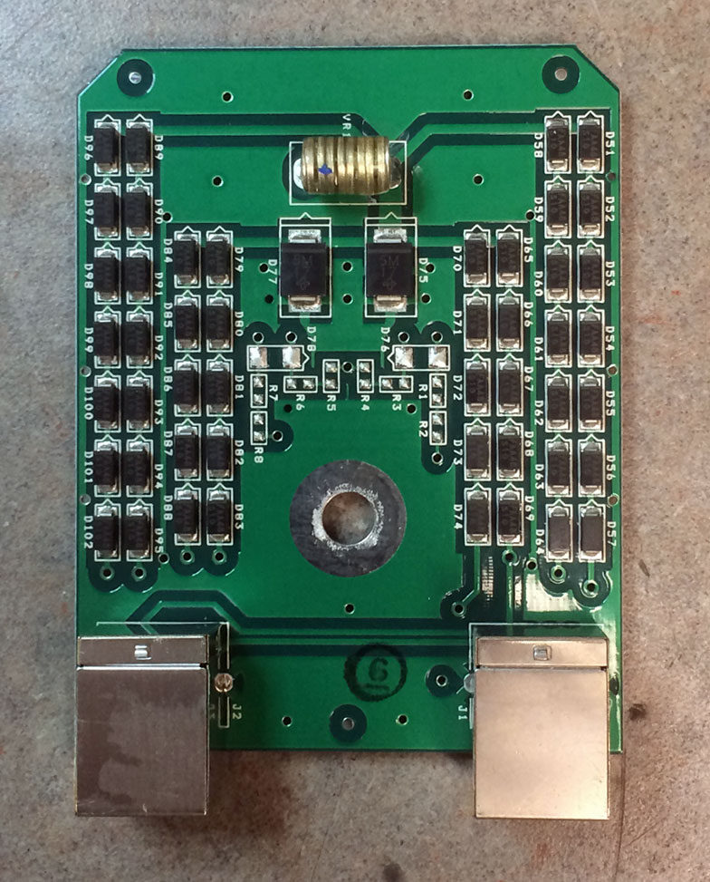
In addition to that, some type of surge suppressor at the base of the tower is also needed. Tramstector makes several products to protect low voltage data circuits.
Transtector APLU 1101 series data line protector
These units are very well made and designed to mount to a tower leg. They come with clamps and ground conductor designed to bolt to a standard copper ground buss bar.
Transtector APLU 1101 series data line protector
There are various models designed to pass POE or even 90 VDC ring voltage.
Transtector APLU 1101 series data line protector
This model is for POE. The circuit seems to consist mostly of TVS diodes clamping the various data conductors.
As more and more of these systems are installed and become a part of critical infrastructure, more thought needs to be given to lightning protection, redundancy and disaster recovery in the event of equipment failure.
Most radio station networks that I have seen are divided along several different lines based on functions. These functions are:
Office network; E-mail, document storage and retrieval, printing, applications like traffic and billing, promotions, music scheduling, and so on
Automation network; automation servers, workstations, and audio editing machines used in production
Audio over IP (AOIP) network; any AOIP consoles, devices, or STL equipment
Voice over IP (VOIP); telephone system
Wireless LAN; WLAN or WIFI
It is helpful, then, to segment the network into different broadcast domains to reduce the congestion on any one network. That is where a good subnetting scheme can be beneficial. Subnets segment the network into smaller parts, reducing the amount of broadcast traffic and increasing network speeds by reducing MAC table sizes, and thus switching and lookup times. They also can secure certain areas of the network from the outside or other subnets, adding a level of security. For example, it may not be a good idea for automation computers or AOIP consoles to have access to the internet. Certain functions in routers and switches can be enabled for that added security.
It is also important to efficiently use IP addresses in a large organization where WANs are used. The better the subnetting scheme, the easier it is to understand and the better it performs. Avoiding or reducing discontiguous networks is key to efficient and speedy routing. That is an important consideration where applications like AOIP and VOIP are concerned
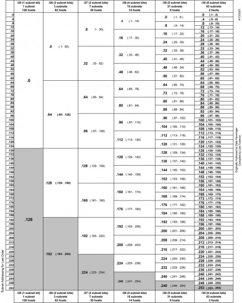
To really understand subnetting, it must be broken down into fundamental parts. This pertains to IPv4, which will likely remain in use for quite some time. The big chart, class B networks:
3nd octet
4th octet
CIDR
Decimal
Wild card
Hosts
3rd Up by
Subnets
00000000
00000000
/16
255.255.0.0
0.0.255.255
65,534
255
0
10000000
00000000
/17
255.255.128.0
0.0.127.255
32,766
128
2
11000000
00000000
/18
255.255.192.0
0.0.63.255
16,382
64
4
11100000
00000000
/19
255.255.224.0
0.0.31.255
8,190
32
8
11110000
00000000
/20
255.255.240.0
0.0.15.255
4,094
16
16
11111000
00000000
/21
255.255.248.0
0.0.7.255
2,046
8
32
11111100
00000000
/22
255.255.252.0
0.0.3.255
1,022
4
64
11111110
00000000
/23
255.255.254.0
0.0.1.255
510
2
128
11111111
00000000
/24
255.255.255.0
0.0.0.255
254
1
256
Class C networks
3rd octet
4th octet
CIDR
Decimal
Wild card
Hosts
4th Up by
SubnetsB
SubnetsC
11111111
00000000
/24
255.255.255.0
0.0.0.255
254
255
256
0
11111111
10000000
/25
255.255.255.128
0.0.0.127
126
128
512
2
11111111
11000000
/26
255.255.255.192
0.0.0.63
62
64
1024
4
11111111
11100000
/27
255.255.255.224
0.0.0.31
30
32
2048
8
11111111
11110000
/28
255.255.255.240
0.0.0.15
14
16
4096
16
11111111
11111000
/29
255.255.255.248
0.0.0.7
6
8
8192
32
11111111
11111100
/30
255.255.255.252
0.0.0.3
2
4
16384
64
11111111
11111110
/31
255.255.255.254
0.0.0.1
0
2
N/A
11111111
11111111
/32
255.255.255.255
0.0.0.0
0
1
N/A
The terms “Class B” and “Class C” networks are outdated. Basically, I broke the chart up along a classful boundary to make it easier to read.
An IP v4 address consists of four octets of binary data. A common example is 192.168.1.154, which in binary numbers looks like this: 11000000.10101000.00000001.11111110. It is converted to base ten numbers (dotted decimal) so that we humans can deal with it. A typical subnet mask seen in many office networks is 255.255.255.0, which in binary looks like this: 11111111.11111111.11111111.00000000. When a router receives a packet, it does something called an “ANDing process.” When a router ANDs, it overlays the subnet mask on the network address and uses the following function: 1+1 = 1, 1+0 = 0 and 0+0 = 0. Thus, in the above example, a router AND would look like this:
Dotted Decimal
Binary Octets
192
168
1
254
255
255
255
0
192
168
1
0
11000000
10101000
00000001
11111110
11111111
11111111
11111111
00000000
11000000
10101000
00000001
00000000
The subnet mask is telling the router to ignore the last octet, thus saving a bit of time and processing power. It may seem very small and insignificant. When considering that routers make sometimes hundreds or thousands of routing decisions in a second, even a small bit of work reduction adds up quickly. Subnet masks allow routers to look at only the layer three network address, ignoring the host portion. This takes advantage of IPs inherent hierarchical addressing system and speeds the process of routing to the proper destination.
Another way to look at it:
IPv4 subnet chart, click for .pdf version
There are three IPv4 address ranges set aside for private (internal) use:
192.168.0.0 to 192.168.255.255 /16
172.16.0.0 to 172.31.255.255 /12
10.0.0.0 to 10.255.255.255 /8
Thus, very large networks can use an internal IP address scheme in the 10.0.0.0 range and have up to 16,777,216 hosts, or 224 addresses minus two, one for the network line address and one for the broadcast address. That would be one giant network clogged with ARP requests, ICMP packets and other miscellaneous multicast messages. A notation of /16 means that 16 bits are used for the network address, the remaining address bits are host bits. A /24 network has 24 network bits and 8 host bits making the available hosts 254.
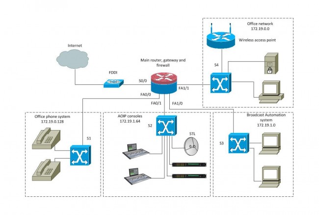
An example of an efficient network would be a medium market operation with six radio station under one roof. This facility has ten studios and a newsroom using AOIP consoles, a VOIP phone system, an automation system, an office network with an internal file server and exchange server. The number of required hosts on each subnetwork is
Office network, servers and wireless hosts: 78
VOIP phone system: 70
AOIP consoles and nodes: 30
Broadcast automation system: 22
Given IP address: 172.19.0.0 /22
In most instances, office networks are usually installed on one class C segment, that is to say, the network mask is 255.255.255.0. However, in the example above, 254 hosts are not needed on the office network, thus it can be divided in half using the subnet mask of 255.255.255.128, leaving the other half for the VOIP phone system. This subnetting scheme would leave 126 hosts on the office network and 126 hosts on the VOIP network. The AOIP console and broadcast automation system can be placed on another class C segment, using the subnet mask of 255.255.255.192, which would give each subnet 62 hosts. All subnets would have room to expand. Each subnet is isolated from the others by a router. The office subnet contains the gateway to the internet, usually .1 or .126 (first or last) IP address.
That would look something like this:
Office network
Line address
First available
Last available
Broadcast
Subnet mask
172.19.0.0
172.19.0.1
172.19.0.126
172.19.0.127
255.255.255.128
VOIP phone system
Line address
First available
Last available
Broadcast
Subnet mask
172.19.0.128
172.19.0.129
172.19.0.254
172.19.0.255
255.255.255.128
AOIP consoles and nodes
Line address
First available
Last available
Broadcast
Subnet mask
172.19.1.0
172.19.1.1
172.19.1.62
172.19.1.63
255.255.255.192
Broadcast Automation system
Line address
First available
Last available
Broadcast
Subnet mask
172.19.1.64
172.19.1.65
172.19.1.126
172.19.1.127
255.255.255.192
That keeps the network segments small but has room to grow. This is a diagram of a converged network:
Radio Broadcast Facility converged network
With a setup like this, reliability is the key to a happy life. The router should be a good Cisco product with four or more Fast Ethernet ports. A second way to do this would be to have four routers plugged into a distribution switch and use OSPF to route between subnetworks. The switches should also be a good Cisco product, which can take advantage of port security options and QoS on the VOIP and AOIP segments. VOIP systems usually require Power over Ethernet (POE) ports, thus that switch can be specialized for that purpose.
Many AOIP systems want to see Gigabit switches or at least Fast Ethernet switches with Gigabit or better backplanes. Any AOIP STL system can be connected to the AOIP network along with other things like AOIP remote broadcast and studio telephone solutions.
Many WLAN access points can be configured as a network router and DHCP server for wireless hosts.
The largest users of the public (i.e. internet) network would be the VOIP phone system and office network. The broadcast automation network may also be a if voice tracking or other program delivery over WAN is used.