As more and more broadcast facilities are moving toward IP data for all types of data transfer including digitized audio, video, telephony, documents, email, applications, and programs. Managing an IP network is becoming more and more important. In most broadcast facilities, Ethernet-based IP networks have been the normal operating infrastructure for email, printing, file sharing, common programs, file storage, and other office functions for many years. Either directly or indirectly, most broadcast engineers have some degree of experience with networking.
With many more IP-based audio consoles, routing systems, STL’s and other equipment coming online, understanding IP networking is becoming a critical skill set. Eventually, all distribution of content will transition to IP-based systems and the current network of terrestrial broadcast transmitters will be switched off.
The difference between an ordinary office network and an AoIP (Audio over IP) or VoIP network is transfer consistency. In an office network, data transfer is generally bursty; somebody moves a file or requests an HTTP page, etc. Data is transferred quickly from point A to point B, then the network goes back to its mostly quiescent state. In the AoIP environment, the data transfer is steady state and the data volume is high. That is to say, once a session is started, it is expected to say active 24/7 for the foreseeable future. In this situation, any small error or design flaw, which may not be noticed on an office network can cause great problems on an AoIP network. The absolute worst kind of problem is intermittent failure.
Monitoring and analyzing data flow on a network can be a critical part of troubleshooting and network system administration. Data flow analysis can discover and pinpoint problems such as:
Design flaws, infrastructure bottlenecks and data choke points
Worms, viruses, and other malware
Abusive or unauthorized use
Quality of Service (QoS) issues
Cisco defines flow as the following:
A unidirectional stream of packets between a given source and destination—both defined by a network-layer IP address and transport-layer source and destination port numbers. Specifically, a flow is identified as the combination of the following seven key fields:
Source IP address
Destination IP address
Source port number
Destination port number
Layer 3 protocol type
ToS byte
Input logical interface
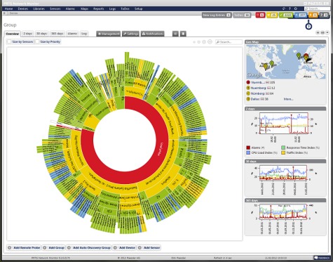
Packet sniffers such as Wire Shark can do this, but there are far better and easier ways to look at data flow. Network monitoring tools such as Paessler PRTG can give great insight as to what is going on with a network. PRTG uses SNMP (Simple Network Management Protocol) on a host machine to run the server core and at least one other host to be used as a sensor. There are instructions on how to run it as a virtual machine on a windows server, which would be the proper way to implement the server, in my opinion.
For small to medium installations, the freeware version may be all that is needed. For larger networks and major market installations, one of the lower-cost paid versions may be required.
Most radio station networks that I have seen are divided along several different lines based on functions. These functions are:
Office network; E-mail, document storage and retrieval, printing, applications like traffic and billing, promotions, music scheduling, and so on
Automation network; automation servers, workstations, and audio editing machines used in production
Audio over IP (AOIP) network; any AOIP consoles, devices, or STL equipment
Voice over IP (VOIP); telephone system
Wireless LAN; WLAN or WIFI
It is helpful, then, to segment the network into different broadcast domains to reduce the congestion on any one network. That is where a good subnetting scheme can be beneficial. Subnets segment the network into smaller parts, reducing the amount of broadcast traffic and increasing network speeds by reducing MAC table sizes, and thus switching and lookup times. They also can secure certain areas of the network from the outside or other subnets, adding a level of security. For example, it may not be a good idea for automation computers or AOIP consoles to have access to the internet. Certain functions in routers and switches can be enabled for that added security.
It is also important to efficiently use IP addresses in a large organization where WANs are used. The better the subnetting scheme, the easier it is to understand and the better it performs. Avoiding or reducing discontiguous networks is key to efficient and speedy routing. That is an important consideration where applications like AOIP and VOIP are concerned
To really understand subnetting, it must be broken down into fundamental parts. This pertains to IPv4, which will likely remain in use for quite some time. The big chart, class B networks:
3nd octet
4th octet
CIDR
Decimal
Wild card
Hosts
3rd Up by
Subnets
00000000
00000000
/16
255.255.0.0
0.0.255.255
65,534
255
0
10000000
00000000
/17
255.255.128.0
0.0.127.255
32,766
128
2
11000000
00000000
/18
255.255.192.0
0.0.63.255
16,382
64
4
11100000
00000000
/19
255.255.224.0
0.0.31.255
8,190
32
8
11110000
00000000
/20
255.255.240.0
0.0.15.255
4,094
16
16
11111000
00000000
/21
255.255.248.0
0.0.7.255
2,046
8
32
11111100
00000000
/22
255.255.252.0
0.0.3.255
1,022
4
64
11111110
00000000
/23
255.255.254.0
0.0.1.255
510
2
128
11111111
00000000
/24
255.255.255.0
0.0.0.255
254
1
256
Class C networks
3rd octet
4th octet
CIDR
Decimal
Wild card
Hosts
4th Up by
SubnetsB
SubnetsC
11111111
00000000
/24
255.255.255.0
0.0.0.255
254
255
256
0
11111111
10000000
/25
255.255.255.128
0.0.0.127
126
128
512
2
11111111
11000000
/26
255.255.255.192
0.0.0.63
62
64
1024
4
11111111
11100000
/27
255.255.255.224
0.0.0.31
30
32
2048
8
11111111
11110000
/28
255.255.255.240
0.0.0.15
14
16
4096
16
11111111
11111000
/29
255.255.255.248
0.0.0.7
6
8
8192
32
11111111
11111100
/30
255.255.255.252
0.0.0.3
2
4
16384
64
11111111
11111110
/31
255.255.255.254
0.0.0.1
0
2
N/A
11111111
11111111
/32
255.255.255.255
0.0.0.0
0
1
N/A
The terms “Class B” and “Class C” networks are outdated. Basically, I broke the chart up along a classful boundary to make it easier to read.
An IP v4 address consists of four octets of binary data. A common example is 192.168.1.154, which in binary numbers looks like this: 11000000.10101000.00000001.11111110. It is converted to base ten numbers (dotted decimal) so that we humans can deal with it. A typical subnet mask seen in many office networks is 255.255.255.0, which in binary looks like this: 11111111.11111111.11111111.00000000. When a router receives a packet, it does something called an “ANDing process.” When a router ANDs, it overlays the subnet mask on the network address and uses the following function: 1+1 = 1, 1+0 = 0 and 0+0 = 0. Thus, in the above example, a router AND would look like this:
Dotted Decimal
Binary Octets
192
168
1
254
255
255
255
0
192
168
1
0
11000000
10101000
00000001
11111110
11111111
11111111
11111111
00000000
11000000
10101000
00000001
00000000
The subnet mask is telling the router to ignore the last octet, thus saving a bit of time and processing power. It may seem very small and insignificant. When considering that routers make sometimes hundreds or thousands of routing decisions in a second, even a small bit of work reduction adds up quickly. Subnet masks allow routers to look at only the layer three network address, ignoring the host portion. This takes advantage of IPs inherent hierarchical addressing system and speeds the process of routing to the proper destination.
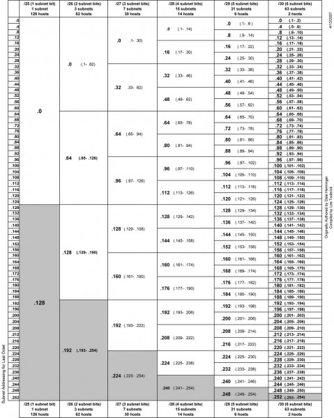
Another way to look at it:
IPv4 subnet chart, click for .pdf version
There are three IPv4 address ranges set aside for private (internal) use:
192.168.0.0 to 192.168.255.255 /16
172.16.0.0 to 172.31.255.255 /12
10.0.0.0 to 10.255.255.255 /8
Thus, very large networks can use an internal IP address scheme in the 10.0.0.0 range and have up to 16,777,216 hosts, or 224 addresses minus two, one for the network line address and one for the broadcast address. That would be one giant network clogged with ARP requests, ICMP packets and other miscellaneous multicast messages. A notation of /16 means that 16 bits are used for the network address, the remaining address bits are host bits. A /24 network has 24 network bits and 8 host bits making the available hosts 254.
An example of an efficient network would be a medium market operation with six radio station under one roof. This facility has ten studios and a newsroom using AOIP consoles, a VOIP phone system, an automation system, an office network with an internal file server and exchange server. The number of required hosts on each subnetwork is
Office network, servers and wireless hosts: 78
VOIP phone system: 70
AOIP consoles and nodes: 30
Broadcast automation system: 22
Given IP address: 172.19.0.0 /22
In most instances, office networks are usually installed on one class C segment, that is to say, the network mask is 255.255.255.0. However, in the example above, 254 hosts are not needed on the office network, thus it can be divided in half using the subnet mask of 255.255.255.128, leaving the other half for the VOIP phone system. This subnetting scheme would leave 126 hosts on the office network and 126 hosts on the VOIP network. The AOIP console and broadcast automation system can be placed on another class C segment, using the subnet mask of 255.255.255.192, which would give each subnet 62 hosts. All subnets would have room to expand. Each subnet is isolated from the others by a router. The office subnet contains the gateway to the internet, usually .1 or .126 (first or last) IP address.
That would look something like this:
Office network
Line address
First available
Last available
Broadcast
Subnet mask
172.19.0.0
172.19.0.1
172.19.0.126
172.19.0.127
255.255.255.128
VOIP phone system
Line address
First available
Last available
Broadcast
Subnet mask
172.19.0.128
172.19.0.129
172.19.0.254
172.19.0.255
255.255.255.128
AOIP consoles and nodes
Line address
First available
Last available
Broadcast
Subnet mask
172.19.1.0
172.19.1.1
172.19.1.62
172.19.1.63
255.255.255.192
Broadcast Automation system
Line address
First available
Last available
Broadcast
Subnet mask
172.19.1.64
172.19.1.65
172.19.1.126
172.19.1.127
255.255.255.192
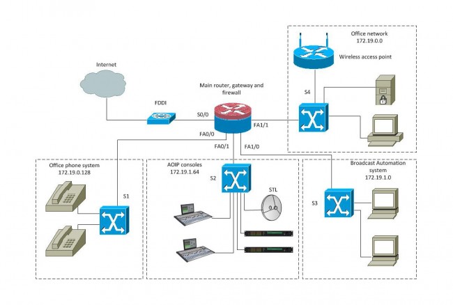
That keeps the network segments small but has room to grow. This is a diagram of a converged network:
Radio Broadcast Facility converged network
With a setup like this, reliability is the key to a happy life. The router should be a good Cisco product with four or more Fast Ethernet ports. A second way to do this would be to have four routers plugged into a distribution switch and use OSPF to route between subnetworks. The switches should also be a good Cisco product, which can take advantage of port security options and QoS on the VOIP and AOIP segments. VOIP systems usually require Power over Ethernet (POE) ports, thus that switch can be specialized for that purpose.
Many AOIP systems want to see Gigabit switches or at least Fast Ethernet switches with Gigabit or better backplanes. Any AOIP STL system can be connected to the AOIP network along with other things like AOIP remote broadcast and studio telephone solutions.
Many WLAN access points can be configured as a network router and DHCP server for wireless hosts.
The largest users of the public (i.e. internet) network would be the VOIP phone system and office network. The broadcast automation network may also be a if voice tracking or other program delivery over WAN is used.