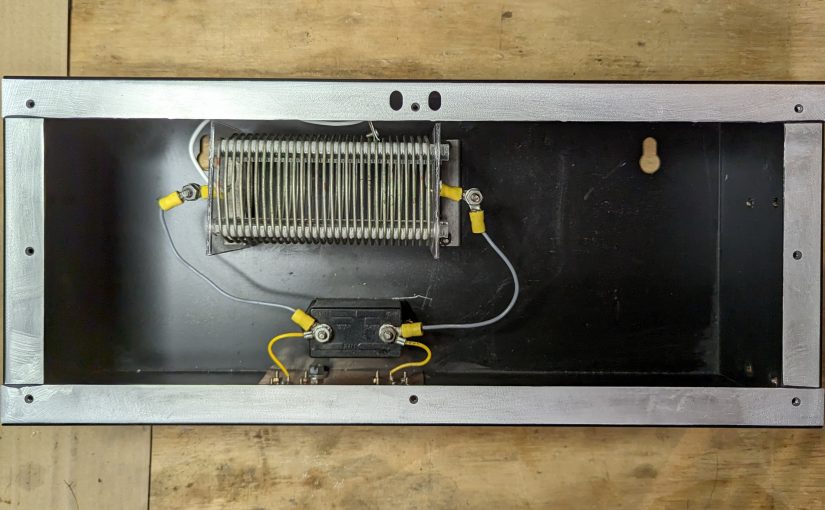
One small RF project that I am working on; a 770 KHz notch filter. I always figure if I am having this problem, then others may be having it too. This is a relatively simple idea, a resonant LC circuit (AKA a tank circuit) tuned to the carrier frequency. It should have a bandwidth of +/- 15 KHz of the design frequency. Another requirement; use the parts I have available. Finally, the environment in which this is to be used is a high-noise room; with lots of computers, LED lights, etc therefore it needs to have excellent RF shielding.
Something like this would work well for anyone that lives around an AM transmitter site and is having problems with receiver sensitivity or transmitter intermodulation.
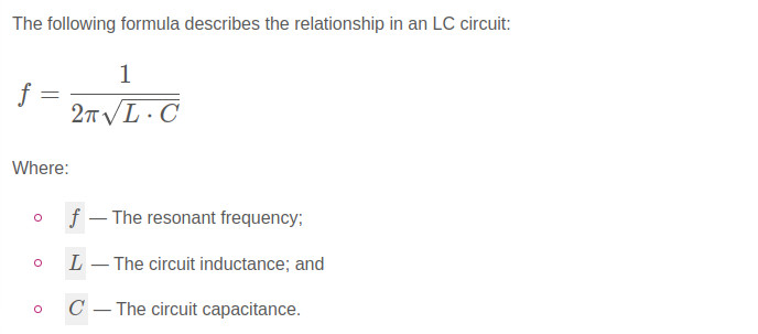
The basic design looks like this:

Time for a trip to the local storage facility known as “The Barn.” In my backyard, there is a small agricultural structure that is used for storage of just about everything. In The Barn, I found several parts salvaged from an old Energy Onyx Pulsar AM transmitter. As such, they are more than capable of receiver operation and could likely handle a fair amount of RF power in the transmit mode.
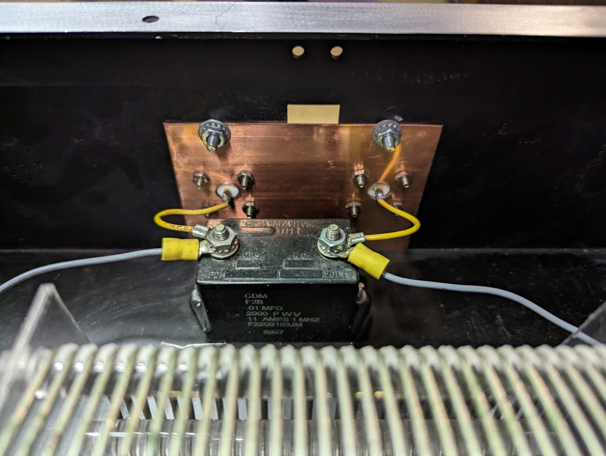
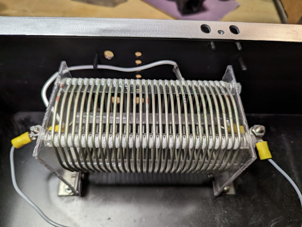
Finding a type F2B 0.01 uF capacitor, rated at 2000 volts and 11 amps, the value of the inductor was calculated. For the inductor, a 20 uH coil with taps will work great. For receive-only applications, much smaller-sized components can be chosen. Also, there are many bandstop filters with multiple poles. Those are great, but I like the simplicity of the parallel resonant LC circuit.
The N connectors were salvaged from I don’t know where and the enclosure used to house a power supply for a Radio Systems console.
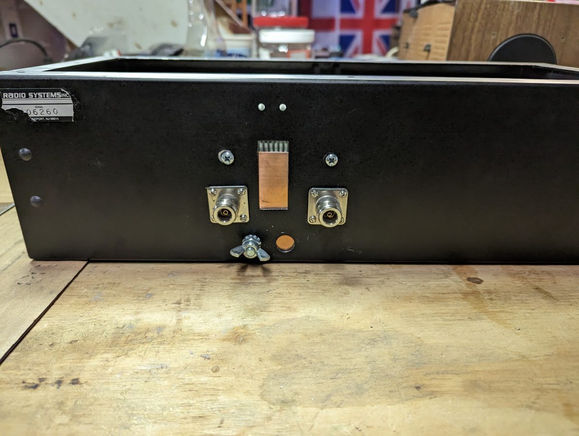
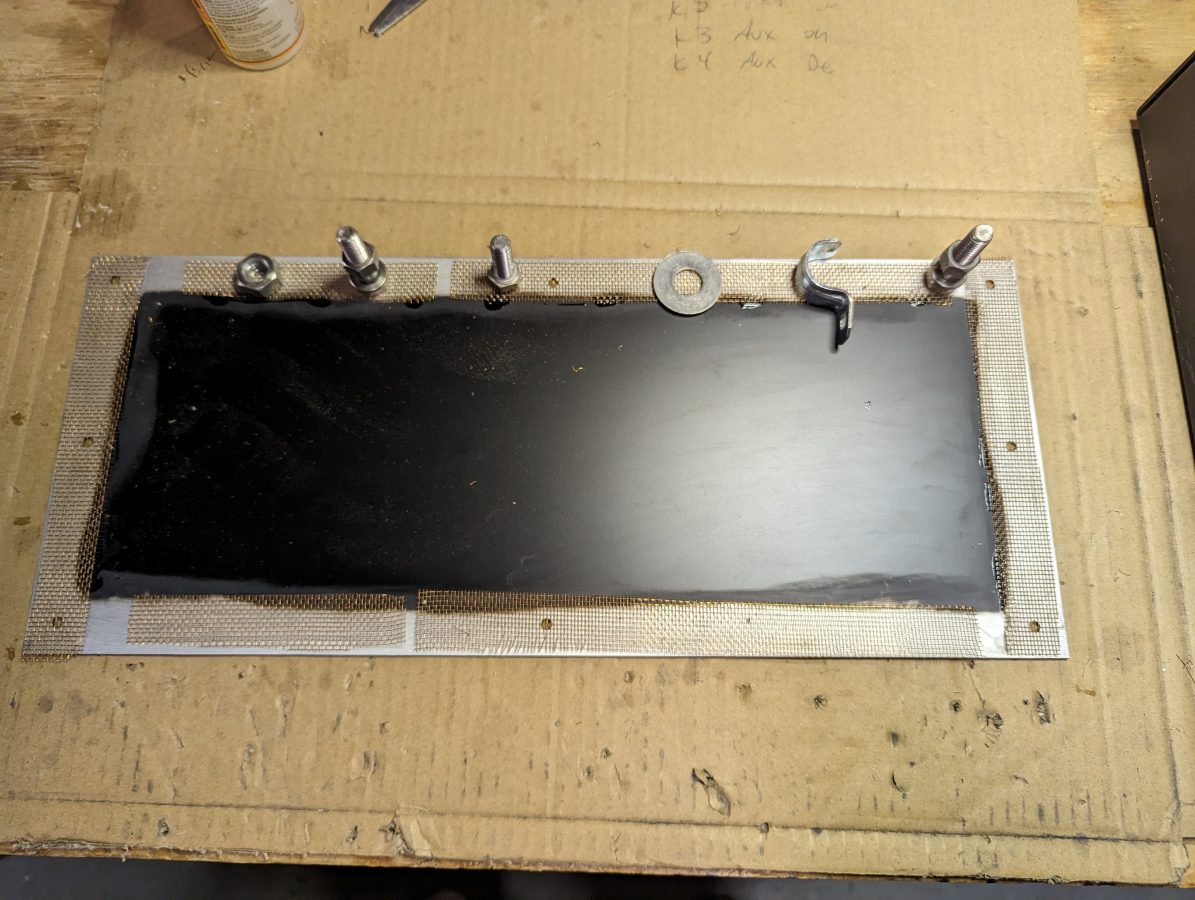
For shielding, I sanded the paint off of the enclosure where the lid is attached and tacked some brass screen down with gorilla glue. This will make a good RF contact surface. The outer of the N connectors are bonded to a piece of copper ground strap which also has a grounding lug on it.
I used the Libra VNA to tune it up:
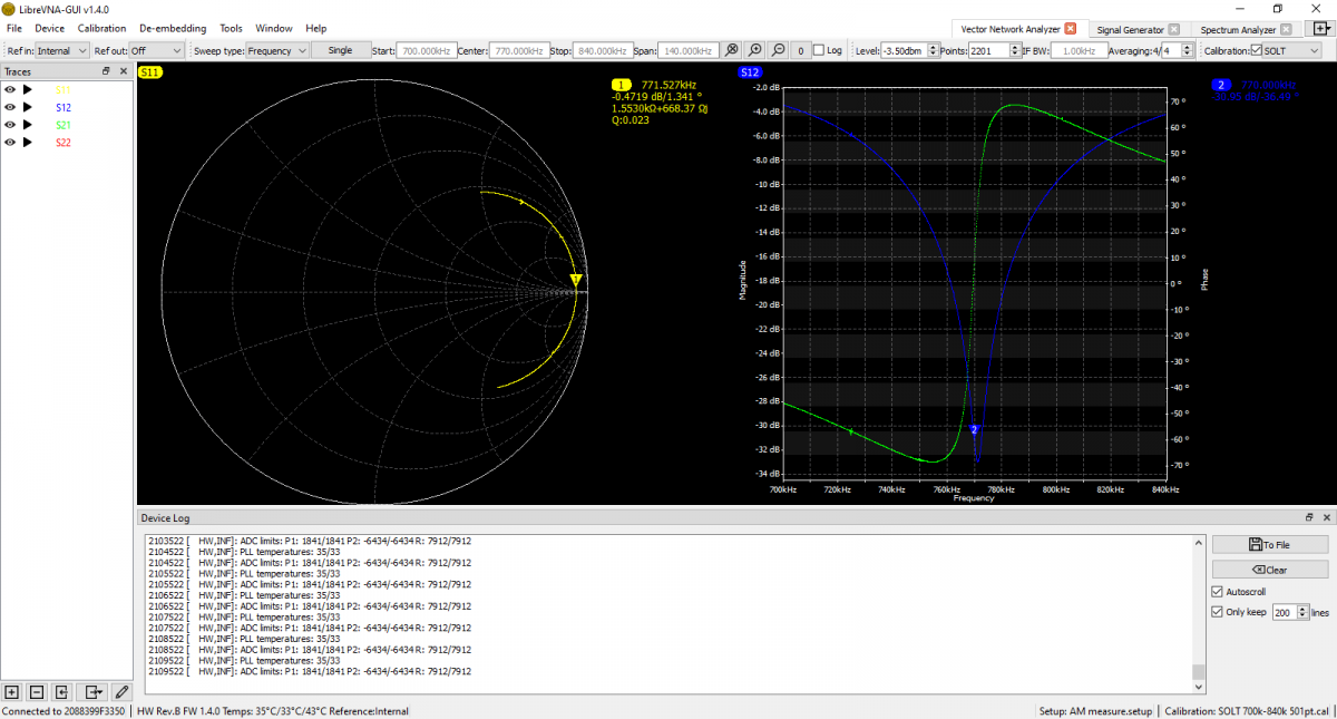
The scan shows it is -31 dB on the carrier frequency. It is -17 dB on 760 KHz and -20 dB on 780 KHz. This is good, because I may still want to listen to the station on the remote receiver. According to the smith chart, it is actually resonant on 771.5 KHz, but that is close enough for this application. I think the resonance went up slightly when I put the cover on after the tune-up.
There are several tank circuit calculators online. It is best to have more capacitance and less inductance to keep the Q of the circuit low and suppress the sidebands as well as the carrier.
