As a part of our studio build-out in Walton, we had to install a high-capacity STL system between the studio and transmitter site. Basically, there are five radio stations associated with this studio and the satellite dish and receivers are going to be located at the transmitter site.
The audio over IP gear is getting really sophisticated and better yet, more reliable. For this application, we are using a Cambium networks (Motorola Canopy) PTP-250 radio set and a pair of Wheatstone IP88 blades on either site. Since there is quite a bit of networked gear at the transmitter site, the IP88s will live on their own VLAN. The PTP-250s will pass spanning tree protocol, rapid spanning tree protocol, 802.1Q, and other layer two traffic.
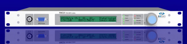
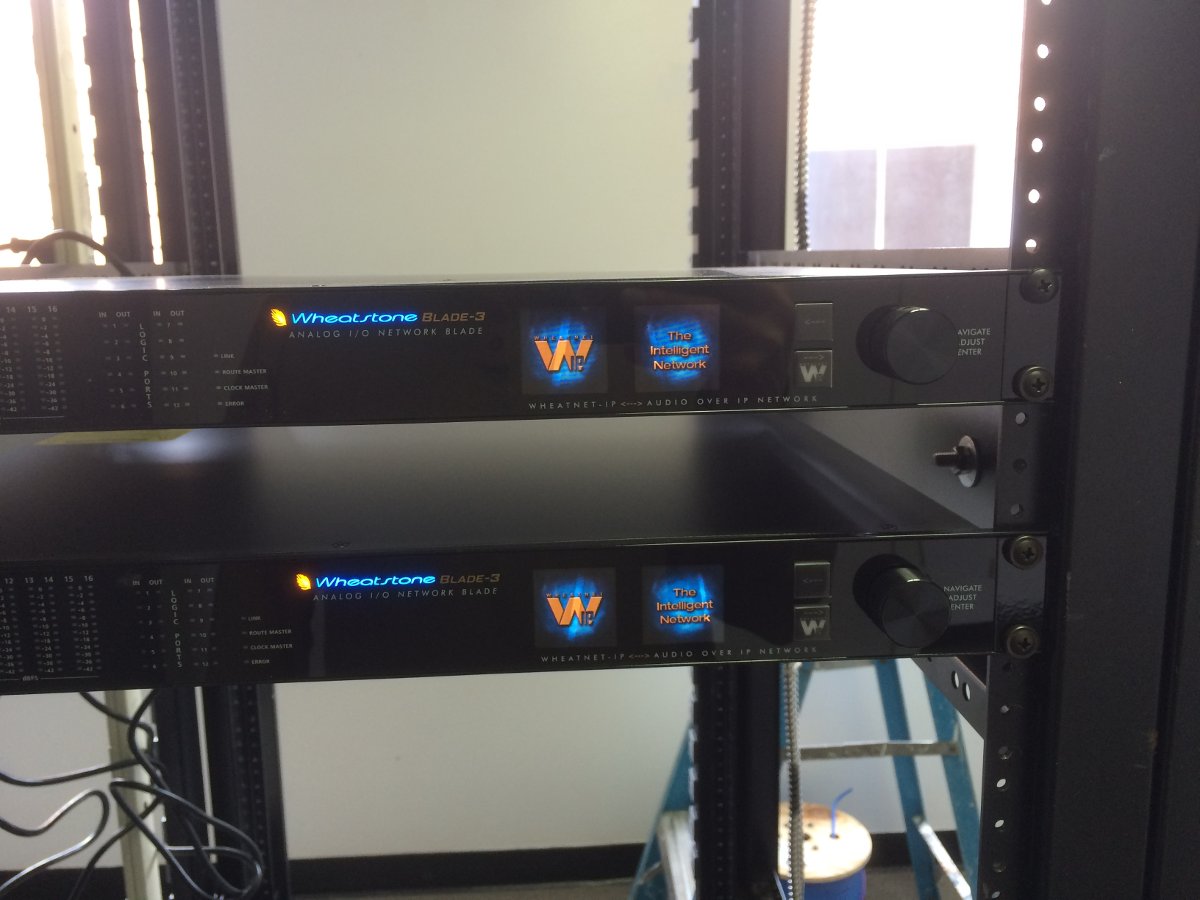
The Wheatsone IP88A blades are the heart of the system. Not only do they pass 16 channels of audio, we can also pass 8 logic closures bi-directionally. This is key because we are shipping satellite audio and contact closures back from the transmitter site. The IP88A setup is fairly easy, once the IP address is entered. The web GUI is used for the rest of the configurations including making the connections between units.
The switches are managed units. The switchports need to be set up via command line to pass VLAN traffic. There is an appendix in the IP88 manual that outlines how to do this with various managed switches. This is the most important step for drop-out free audio. The switchports that connect to the two radios are set up as trunk ports using either VTP or 802.1Q.

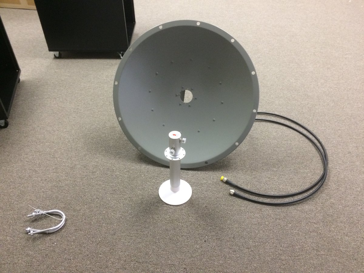
The PTP-250 radios were already on hand, new in the box. They are built really well and look like they should not break in a year or so. These particular units are connectorized, therefore an external antenna was needed. There are many such antennas, this system ended up with an RF Engineering & Energy 5150-5850 MHz dual-polarized parabolic dish with RADOMES. RADOMES are necessary to prevent ice or snow build up in the winter.
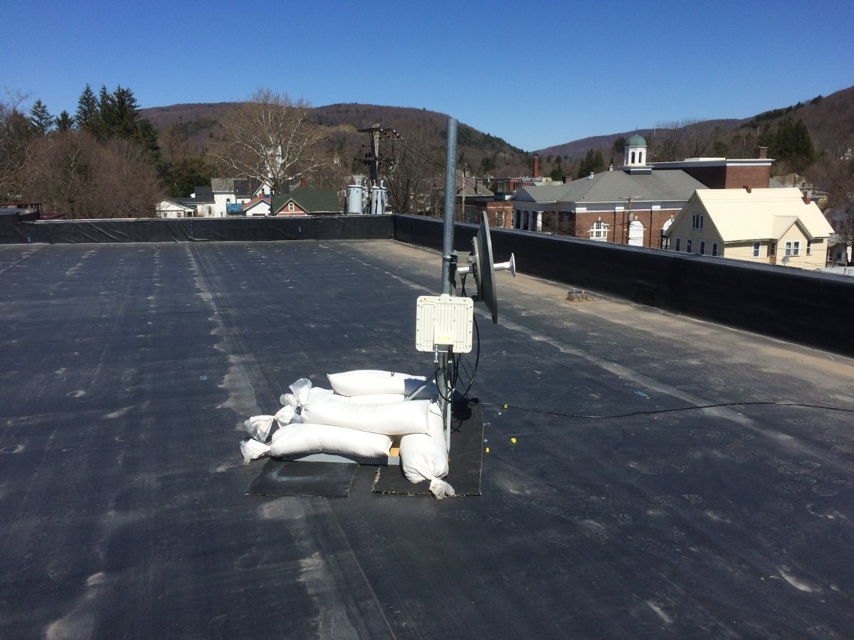

Since the path is only 3.37 miles (5.43 kilometers), I set them up with a 40 MHz wide channel. This is a rural, small-town setting. When I looked at the 5.8 GHz band on a spectrum analyzer, it looks fairly uncongested. These are MIMO single or dual payload selectable. I will try them as single payload units since the path is short and the band is uncongested. This should keep the throughput high.

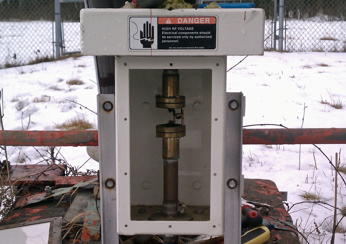
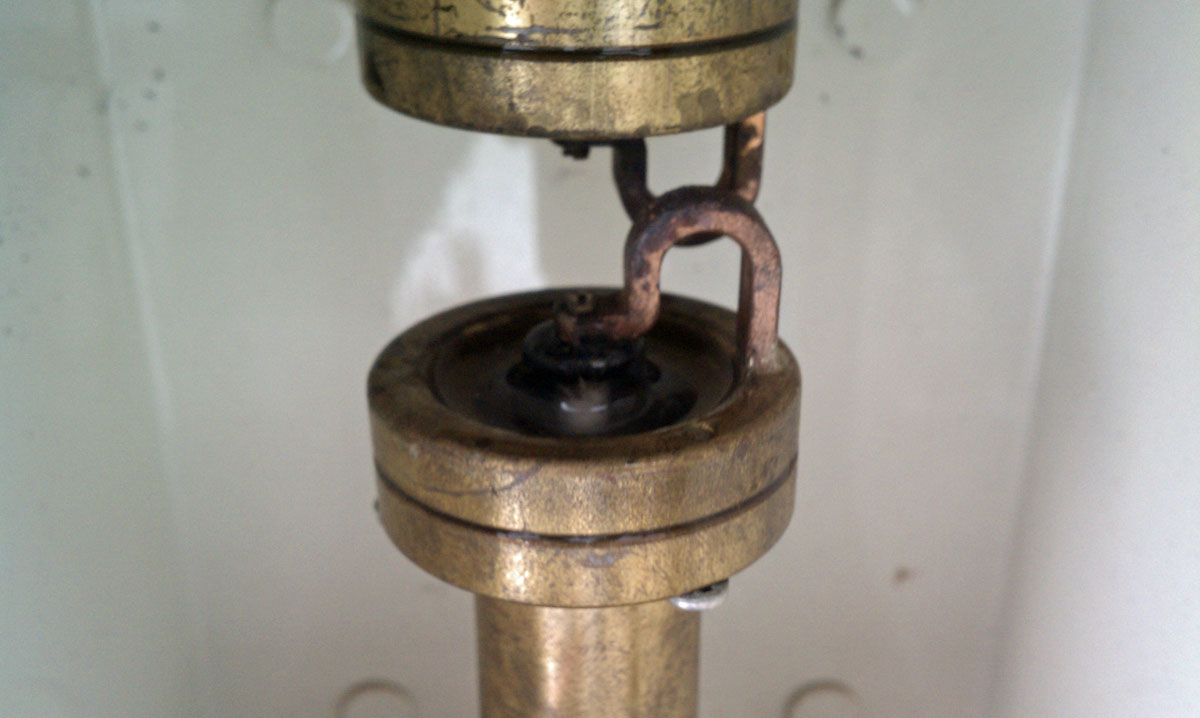
The PTP-250s use POE injectors in mounted in the rack rooms. CAT5e shielded cable with the proper connectors properly applied is a must for lighting protection. The PTP-250 units came with Cambium PTP-LPU lightning protectors. I also installed Polyphaser AL-L8XM-MA type N surge suppressors on each RF port of each PTP-250.