Nanobridge M5 wireless LAN link, Part II

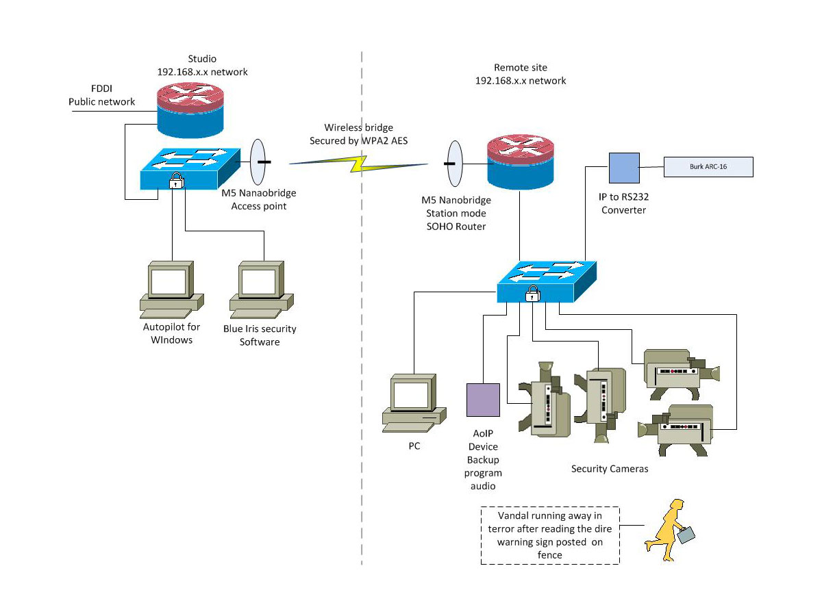
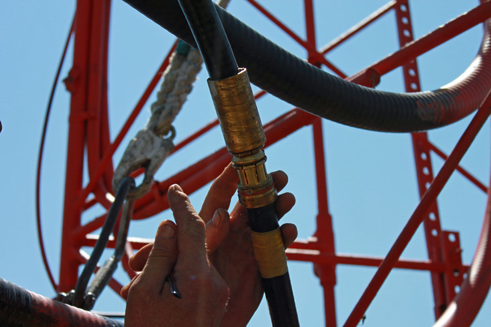
After a bit of delay, we were able to return to the WICC transmitter site to install the Wireless LAN link.  The installation was pretty straightforward.  The studio unit was mounted on an existing STL tower on the top of the elevator room, the transmitter unit was mounted on an existing pipe on the roof of the transmitter building.

M5 Nanobridge mounted on transmitter building with radome
M5 Nanobridge mounted on transmitter building with RADOME

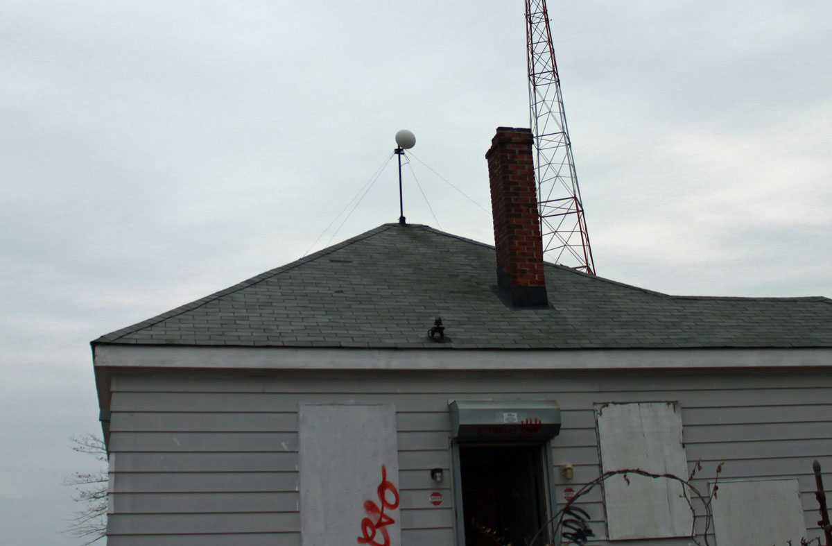
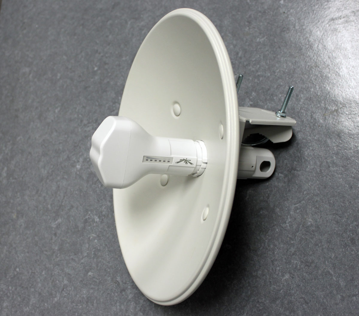
I included RADOMEs for a couple of reasons; first, there is a lot of critters around of the two-legged and winged kind. The upright two-legged critters may be attracted to the signal-strength lights at night. This unwanted attention could invite the juvenile delinquent’s bored teenagers to throw various objects found laying around on the ground at the antenna, damaging it.  The winged type critter may be inclined to view the feed horn as a good nesting location. The other reason is this site gets a lot of rain, wind, ice, and snow, therefore the RADOMEs afford some protection against the weather.

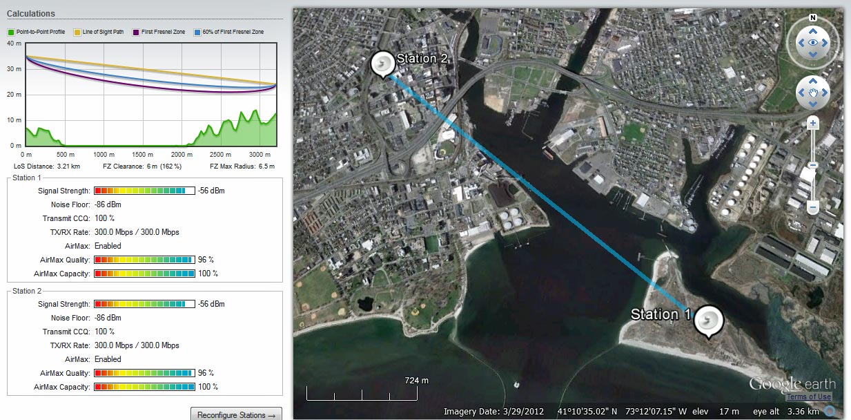
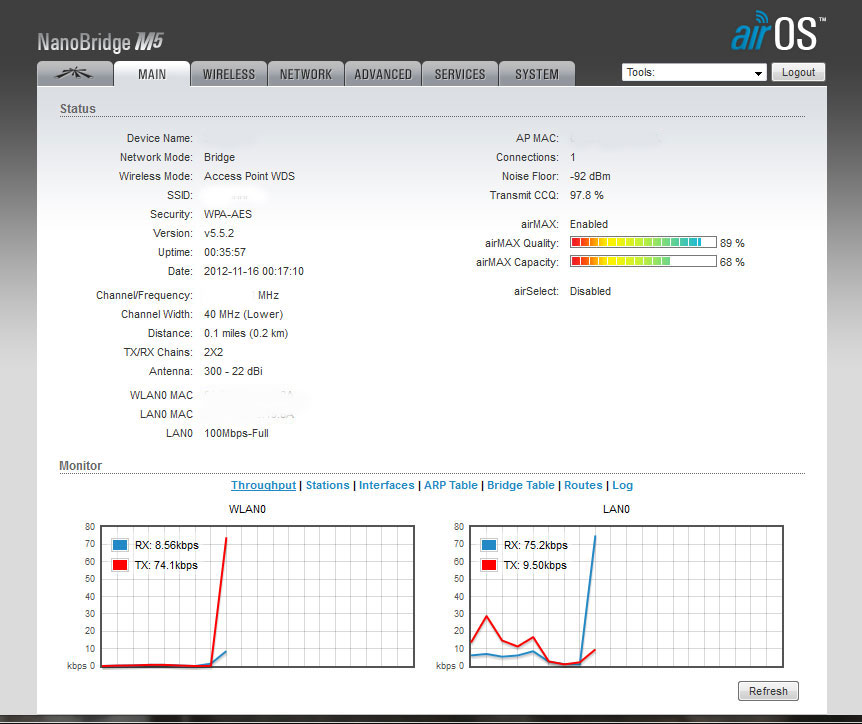
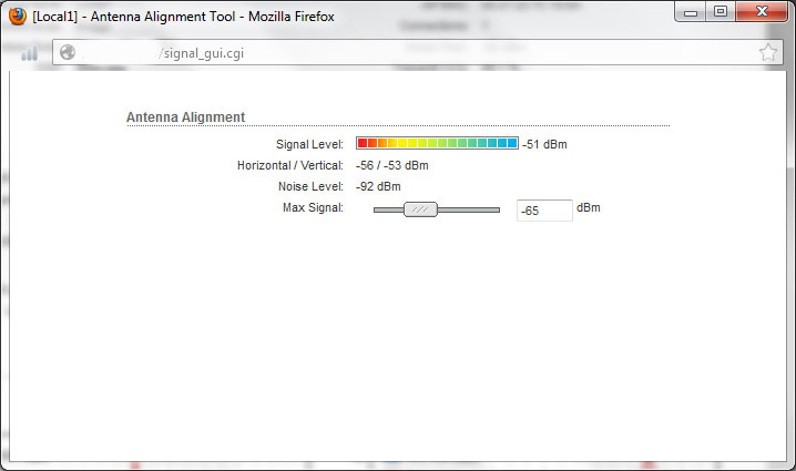
Aiming the antennas was pretty straightforward, but requires at least two people.  Using landmarks, we aligned the dishes in the general direction of each other.  Both ends of the system were turned on and we had a -89 dBm signal path, and somewhat surprisingly, the radios linked up and my laptop grabbed an IP address via DHCP.  Using the signal strength meter on the side of the antenna, each dish was peaked in turn:

M5 Nanobridge Antenna signal strength meter

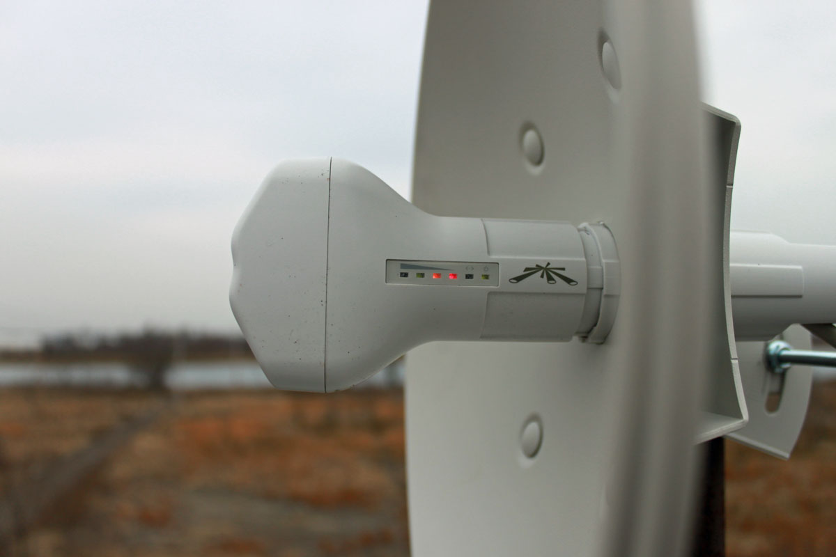
Then, somebody on either end went below and looked at the signal strength screen on the web interface while the other end peaked.  In the end, we had about -65 dBm signal strength, which is somewhat less than the -58 dBm predicted.  I think we can do better, so on the next clear day, I am going to peak the signal again.

The data rate initially reported was over 100 MBPS, however, once I started transferring files back and forth, that dropped to about 50 MBPS.  If it is raining, that rate drops to about 35 MBPS, which is still far above what we need this link to do.  As a test, I streamed a youtube video, downloaded a Windows update, loaded several web pages, and checked my email simultaneously.  There were no issues with the data rate while those tasks were being preformed.

It is quite amazing to me that these little inexpensive radios can work so well.  My boss thinks that they will be blown up by lightning during the first thunderstorm of the season.  I don’t know.  There are several of these units have been installed at mountaintop tower sites and have been working for several years without issue.

Next step, installing the IP cameras and warning signs on the fence, setting up the monitoring software, etc.

Transmitter site security cameras

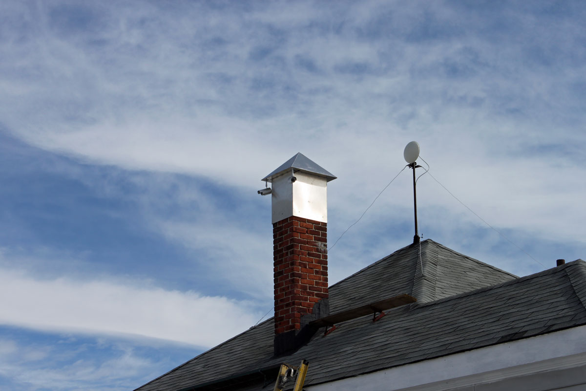
Cameras mounted on old chimney platform.  This is the first set of cameras covering the south, north, and west approaches.  A fourth camera will be mounted on the back of the building covering the east approach.  Then, under the eves’ cameras will be mounted on all four corners of the building and the generator shed.  If anything moves, it will be recorded.

Ubiquiti Nanobridge M5 IP radio

I am in the process of installing a pair of the Nanobridge M5 units as an IP network link between a transmitter site and the studio location. The path is relatively short, about 1.5 miles over mostly water.  The main reason for this is to replace the analog phone lines used for remote control data and backup programming delivery to the transmitter site.  One added benefit, we are also installing several  IP cameras to keep an eye on the place.  We purchased the Nanobridge system for $80.00 per side.  The price is pretty good, but the configuration and testing are a bit intensive.

Network diagram
Network Diagram

There are many versions of these spread spectrum radios, some are licensed, and some are license free.  These are inexpensive, license-free links that I would count on for short paths or use in non-congested areas.  In congested areas, licensed (Part 101) links should be used, especially for critical infrastructure like STLs.

Since I dreamed up this idea, I figured I should make sure it is going to work before recommending it to the powers that be.  I have learned the hard way, almost nothing is worse than a failed project with your name on it.  Better to over-study something than to go off half-cocked, spend a bunch of money, then realize the idea was flawed from the start.  See also: Success has a thousand mothers but failure is an orphan.

Nanobrige path study, 5.8 GHz
Nanobrige path study, 5.8 GHz, moderate noise floor, 1.5 miles

Looks pretty good.  300 MB/s bi-directional which is faster than the Ethernet port on the unit.  This will be set up in bridge mode with pretty robust encryption.  The transmitter site side is configured in the router mode, creating a second class A network at the remote site.

Nanobridge M5 22 dBi antenna

Next step, configuring the units.  The Nanobridge units were set up in a back to back configuration in the engineering room.  Each end comes with a default IP address of 192.168.1.20.  The units were several steps behind the latest firmware version, therefore the firmware was upgraded first.  The default admin user, password, and IP addresses were changed.  There is no greater security risk than default user and password.  The wireless security feature is enabled using WPA2-AES PSK and a greater than 192-bit access code.  The unit allows for any access code length up to 256 bits.  With a key of between 192 and 256 bits, the number of possible solutions is between 6.2771 E 57 and 1.1579 E 77, which should be pretty hard to crack.  By way of reference, a 192-bit password has 24 ASCII characters and a 256-bit password has 32 ASCII characters.

Air OS main screen
Air OS main screen

The system requires an access point, which is configured for the studio side making the transmitter site stub network the station side.  The access point is configured not to advertise its SSID, thus it should be transparent to anyone sniffing around.  The WLAN is configured as a layer two bridge, which will cut down on the data overhead, as layer three framing will not need to be opened between the two units.  The transmitter site network is set up with SOHO router function built into the Nanobridge.  One static route is needed to get to the main network.  Once the security cameras are installed, PAT may need to be used to access individual camera units via the public network.

Ubiquity air os signal strength screen

Next step, deploy the units and aligning antennas.  These are 22 dBi gain antennas, which have a pretty tight beam width.  Maximum transmit power is 23 dBm, or 200 mW.  The transceiver/antenna unit has a handy signal strength meter on the side of the unit, which is good for rough in.  The web interface has a more precise meter.  In addition to that, there is a java based spectrum analyzer, which is very handy for finding open channels in congested areas.  These units can also be used on UNii frequencies with special requirements.

According to the manufacturer, UV-resistant shielded Category 5e cable should be used for outdoor installations.  We have several spools of Belden 1300A, which fits the bill.  The shielded Cat 5 is necessary for lightning protection as the cable shield offers a ground path for the antenna unit.  The antenna mounting structure is also grounded.  I did not take the equipment apart to examine, but I believe the POE injector and antenna have 15KV TVSS diodes across all conductors.  It will be interesting to see how these units do at the transmitter site, where there are two 300-foot towers that likely get struck by lightning often.

More pictures of the installation when it is completed.

Next step, put the system into service and monitor the link.  At the transmitter site, a re-purposed 10/100 Ethernet switch will be installed for the cameras, computer, IP-RS232 converter, and anything else that may need to be added in the future.  One thing we may try is an Audio of IP (AoIP) bridge like a Barix or Tieline for program audio and room audio.

The Polyphaser IS-PT50HN-B

I found this on the floor at an old transmitter site:

Polyphaser IS-PT50HN-B DC block surge suppressor

Since it appears to be discarded, I ignored the dire warnings and opened it up to look inside:

Polyphaser IS-PT50HN-B DC block surge suppressor

This is is a DC blocked lightning surge suppressor designed for 890-980 MHz, 750 watts maximum.  The two parallel wires represent a capacitor, coupling the radio to the antenna, the inductor acts as an RF block to the gas discharge tubes.  The design is such that the inductor acts to block the normal in-use radio frequencies but will allow the 10-30 KHz lightning pulse to pass to the gas discharge tubes and thence to ground.  The inductor and gas discharge tubes are on the antenna side of the unit.  I measured these units with a DVM and they all appear to be good.

My only comment on this unit is that there is no effort to maintain the transmission line impedance.  At the upper end of the UHF spectrum, this can lead to return loss and wasted power.  For a receive application, it may not be so bad, but for a transmitter, I would rather use something else.

For lower VHF frequencies, something like this can be DIY fabricated with minimal expense and effort.  The case must be bonded to the station ground.

Whatever can happen, will happen

This is a universal truism that can also be expressed as “Murphy’s Law.”  I don’t rightly know how Murphy received credit for this, however, I chalk it up to either the luck of the Irish or the gift of self-promotion.  Either way, that principle was demonstrated again with a 950 MHz STL link between Mt. Beacon and Peekskill, NY for WHUD.

I noticed, while doing some transmitter maintenance, the receive signal strength of the STL had dropped from 300 µV to 30 µV.   That is an alarming development.  Therefore, we scheduled a tower crew for the next day, not wanting to go off the air over the coming holiday, which would be a sure bet otherwise.  Upon arrival, the tower crew noticed a strange thing in the STL transmission line at the base of the tower, which looked like some type of a splice.  Truth be told, I have been associated with this station since 1999 and had never noticed the splice before.  This STL system was installed in 1998 when the station’s studio moved from Peekskill to Beacon.   I can say, of all the things that have gone wrong over the years, this STL system was always very reliable.  Regardless of that, I quick check with a spectrum analyzer showed a 3 dB return loss at 137 feet (41.75 m), exactly the distance from the transmitter room to the base of the tower.

3 dB return loss, distance to fault 137 feet

A 3 dB return loss coincides exactly with the drop in received signal strength at the other end of the path.  Thus, the tower crew took apart the splice and water poured out of it.  I would estimate at least 4-6 ounces of water (180 ml), perhaps more.

7/8 coax cable splice connector
7/8 coax cable splice connector, opened up

We then began to take in the details:

  • The 7/8 coax coming out of the building was Cablewave FLC78-50J
  • The 7/8 coax going up the tower was Andrew LDF4-50A
  • The splice connector was Andrew L45Z
  • The center conductor threaded connector did not fit properly into the Cablewave cable, it was too loose.
  • The cable was chaffing on a tower leg, about 50 feet above the splice because it was not properly secured to the tower
  • The 7/8 splice connector was missing an O ring on the backnut of the Cablewave cable

Thus, water ingress causes the high return loss.  Problems with this system began immediately after Hurricane Irene, at the end of last August.  We were able to make a temporary fix using two type N connectors of the proper manufacturer for each type of cable.  The radio station returned to air just before noon,  about 45 minutes after turn off.  After the repair, the return loss dropped to about 20 dB, which is good.

The permanent fix is for the entire run of cable from the transmitter room to the STL antenna to be replaced.  That type of line splice should have never been used on a 950 MHz STL, and it was certainly wrong to mix cable types with an Andrew connector.  Those little details will always manifest themselves eventually.