The malfunctioning STL antenna

Right after Tropical Storm Irene, it was noted that the STL signal strength at the WHUD transmitter site was low. Normally it was 300+ µV, but now reading around 100 µV, which is a problem. Upon further investigation, it was revealed that the STL transmitter on the intermediate hop had higher than normal reflected power.

Time to call the tower crew.

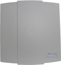
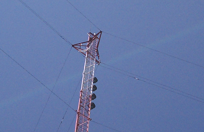
The STL transmit antenna for WHUD’s STL (WPOU464) hop is a Scala Paraflector (PR-950), mounted at the 280-foot level on this tower:

Scala PR-950 on a guyed tower

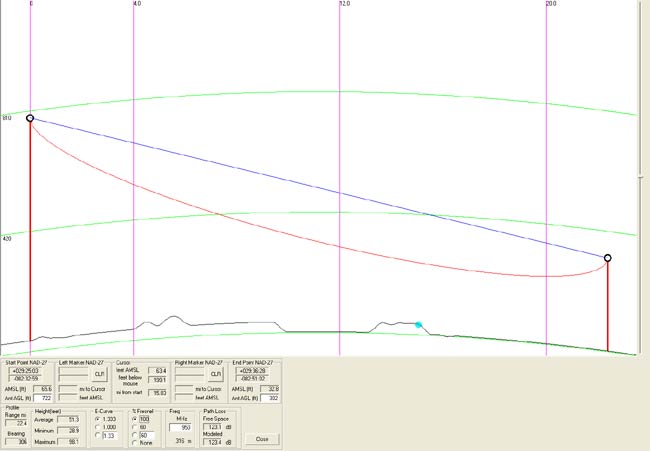
The fact that it happened after a major storm and the transmitter was showing higher than normal reflected power indicates a problem with either the antenna or the jumper between the 7/8″ Cablewave coax and the N connector on the antenna.  A measurement with a spectrum analyzer shows very high return loss:

WHUD STL antenna return loss

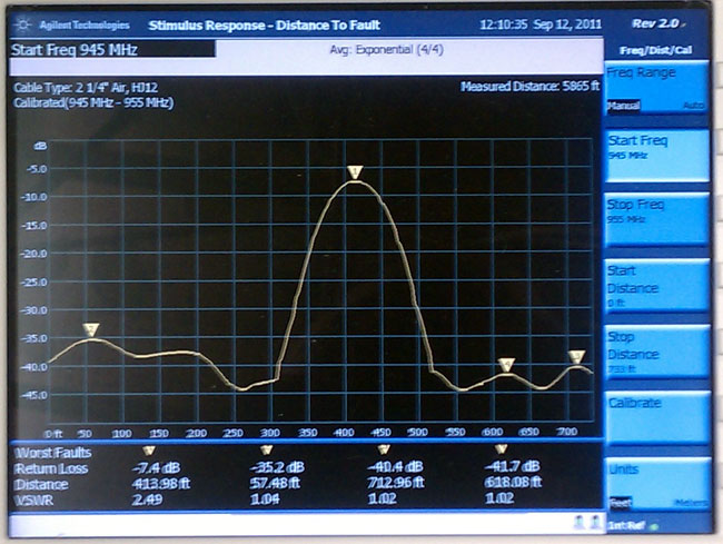
This shows the distance to fault 413 feet, with a return loss of -7.4 dB.  That distance is either near or at the antenna and -7.4 dB indicates a lot of reflected power.  We had the tower climber take apart the jumper connections and terminate the jumper with a known good 50-ohm load.  The return loss did not change.  We then had him swap out jumpers and reconnect to the antenna.  That did the trick:

WHUD STL antenna with new jumper

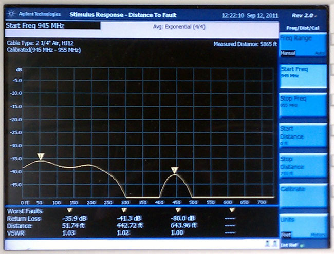
Much better, most of the power is now being radiated by the antenna, the VSWR is 1.02:1.  The impedance bump at 51 feet is a sharp bend in the coax where it is attached to an ice bridge.  Reconnecting the transmission line to the transmitter and turning it on confirms that all is normal again.  The problem with the jumper was found in one of the connectors, it was full of water.

Water contaminated Andrew flexwell connector
Water-contaminated Andrew flexwell connector

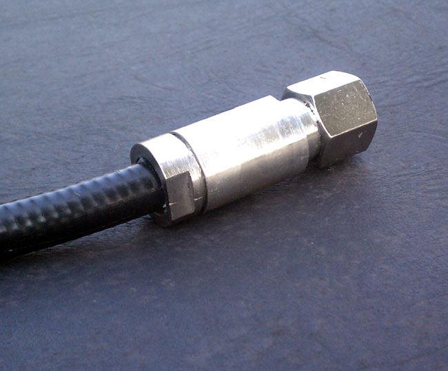
I cut away the boot, water had entered the connector from the back because waterproofing and tape was not applied all the way to the coax.  This was installed in 1998 when the station moved from Peekskill to its current location in the town of Fishkill.  The fact that it happened now in the nice weather when Mt. Beacon is still accessible and not in the middle of winter means the radio gods are smiling on us.

Wireless LAN bridges and STLs

Wireless LAN technology has been around for quite a while.  Point-to-point 2.4 and 5.8 GHz spread spectrum hardware has also been around for some time.  These systems operate in the ISM bands at relatively low power levels and are license free.  There are several different makes and models, however, they all have some similar specifications.  Most have DS-1 (T-1) or ethernet 10 base T or 100 base T 802.3 architecture.  Some are field configurable for either format.

The advantage of using 802.3 ethernet is the availability of ethernet sound cards and the possibility of making inexpensive audio to ethernet A/D converter.  However, if a station is currently using telephone company DS-1 service, then they likely have the audio to DS-1 multiplexers on hand.

Axxcelera AB Full Access outdoor unit

I have used the Axxcelera point to point system as an inter-city relay for a satellite downlink.  Axxcelera is owned by Moseley, which has a long history in the STL business.  The point-to-point system has an indoor unit, which has the RJ-45 ports, and an outdoor unit, which has the RF section and an integrated antenna.  The two units are connected via Cat 5 cable (be sure to use UV resistant cable) through a power injection port.  The newer units do not need the power injection port.  The system gain is about +46 dBm and the claimed effective range is 20 miles.  I’d suspect it to be somewhat less than that with the integrated antenna.  There is also an N connector for an external antenna, making the outdoor unit a MMA (Mast Mounted Amplifier).

The indoor unit came configured with four 10 base T ports, which we reconfigured for DS-1 service.  We connected a QEI CATLINK T-1 mux with several 7.5 KHz audio channels and one control channel connected to a broadcast tool DSC 3264 (Starguide satellite receiver channel controller) that allowed the station to change channels on the fly.  It took some doing, but in the end, the system worked well.  The path was about 1/2 mile through downtown buildings, it was line of sight but did not have full Fresnel clearance.  I never heard of any dropouts.

The other system that I have used is the ADTRAN TRACER.  This system is different in that it does not have an integrated antenna, an external antenna is required.  We installed this over an eight-mile path using two six-foot grid parabolic dishes (Radio Waves G6-2.4NF) on 2.4 GHz.  The primary configuration is a rack-mounted indoor unit with either four or eight 802.3, E-1, or T-1 ports.  These ports are not field configurable.  The antenna connector is a type N.  There is also a split configuration available; an indoor unit with the T-1 ports and an outdoor MMA.  This setup is best used where transmission line lengths would create prohibitive losses.  MMA’s are not my first choice in these systems, there are too many things that can go wrong when active components are mounted high above ground level.

This system replaced two Telephone company T-1 lines and is used as an STL for two stations and an inter-city relay for a satellite downlink site.  It also extends the office LAN (802.3 ethernet) to the transmitter site where a backup audiovault server lives.  This is accomplished through a T-1 port using an ethernet to T-1 bridge.

ADTRAN Tracer 6000 series microwave radio

ADTRAN also created a path analyser spreadsheet.

The license-free aspect of these system makes them easy to deploy.  There are several frequency plans available and the paths are fairly robust.  In highly congested areas, however, interference may become an issue.  Of course, because they are unlicensed, frequency coordination would be a real problem.  Axxcelera has the ExcelFlex which is a unit requiring a license that can run in any frequency band from 6-38 GHz

It’s cold enough to…

Cause the STL receiver to unlock.  A quick peak at the thermometer this morning showed -12° F outside.  Meanwhile, out on the island, the WICC TFT STL receiver decided that it was just too cold to continue and gave up the ghost.  Weak sister.  This created quite a bit of hiss on the WICC signal until about 11 AM, when the program director finally called me to tell me of the situation.

Via remote control, we switched over to the backup analog 8 KHz 15 KHz TELCO line, which sounds fine, given the talk radio program material.

Unfortunately, vehicle access to the transmitter site is now gone.  I have the option of taking the Bridgeport harbor master boat over to the dock and walking .9 miles, or driving to the Long Beach parking lot and walking 1.3 miles in order to repair it.  This will likely be tomorrow, as the weather is supposed to be better, 36°F and light snow.  Well, it is what I get paid to do.

Pleasure Beach, Bridgeport, CT

Regarding the analog 8 KHz TELCO line, that is an anomaly.  These analog circuits where used to wire the country together, once delivering all of the network programming to affiliate stations before the widespread use of satellites.  They require unloaded dry pairs and normally have an equalizer on the Z (far) end.  Nowadays everything is digital, try and find a tech to repair one of these circuits when it goes down.  Fortunately, this is a short distance circuit.

STL paths

I learned this one the hard way, all climates, and terrain are not equal.   An important detail when planning a Studio to Transmitter Link.  The RF STL  is usually in the 950 MHz band, although lately, people have been using 2.4 and 5.8 GHz unlicensed systems with good results.  What works well in the northeast, for example, might not work that great in Florida, where tropospheric ducting and multi-path can create reception problems.

One example of this happened in Gainesville, Florida.  A station there had a 15-mile path over flat ground with tall towers on either end.  It had full line of sight and Fresnel zone clearance.  Ordinarily, the signal strength was -65 dB, which is about 25-30 dB of headroom for the equipment being used.  However, in the mornings, most often in the late summer or early autumn, there would be brief dropouts of a few seconds.  After two years of suffering through the mysterious morning dropouts, we finally rented a plane and flew the STL path, only to discover there was a swamp right in the middle that was not on the topographical map.  On those mornings when dropouts occurred, it was surmised that dense fog would rise up, causing the RF path to bend and creating multipath at the receive antenna.  Since it was a Moseley Starlink, the digital demodulator would unlock due to high BER.  The signal strength never moved off of -65 dB.

Of course, had this been an analog STL, it would not have dropped out, although it may have gotten a little noisy for a few minutes.

950 MHz STL path study

I have learned to be very conservative with my STL path analysis, using software tools like RF Profiler to look at the theoretical path, but also surveying ground obstacles like trees and buildings, which are not accounted for in the USGS terrain database.  There are several RF software programs out there that will do the same thing.

Last week, when a station manager insisted that an STL path was possible from a proposed new studio location, I deferred to the path study, which showed only about 50% Fresnel zone clearance.  While it was true that the path is less than a mile, and it is also true that one can see the top of the transmitting tower from the roof; trees, buildings, and even an access road create problems that could potentially cause STL dropouts.  We are not going down that road again.  The station manager, whose background is in sales, was told to find another location or order a TELCO T-1.