Does this thing work?

I found this obviously used GPS antenna in a storage room at one of our client’s transmitter sites.

How often have you asked that same question about some older piece of equipment lying around? There is a trend among engineers to hold off on getting rid of old equipment because someday, perhaps, it can be used again. Often, these treasures so lovingly stored away for many years or decades do not work when that day finally comes along, leading to disappointment and despair.

This GPS antenna falls into that category.

What to do, what to do…

Fortunately, there is an easy way to test this antenna and do other things with GPS. I had one GT-U7 GPS receiver module left over from a previous project.

Couple that with an FT232RL FTDI USB to serial converter and a bit of software from u-blox. The GPS receiver is a clone of a u-blox M6 GNSS chip, meaning the u-center software will work with it. That is a free Windows software application. The u-center software is great because you can access all of the options on the GPS receiver chip. Since this is to be used for testing, I enabled the LNB voltage sensing and protection features in the antenna configuration menu. Thus, the software will notify if there is a short circuit or open circuit in the GPS antenna under test.

GPS survey receiver parts

I had this nice Hammond 1590WB diecast enclosure left over from a previous project. It’s probably a bit of overkill, any small enclosure would work, but why buy something new?

Here is a complete list of parts:

  • GT-U7 GPS Module Satellite Navigation Positioning GPS Receiver, u-blox NEO M6 clone, Amazon B07P8YMVNT, $12.99
  • FT232RL Mini USB to TTL Serial Converter Adapter Module 3.3V/5.5V, Amazon B00IJXZQ7C, $6.49
  • IPEX to SMA jumper, RG-178, 4 inch, Amazon B0B9RYL56H, $8.78
  • Hammond Manufacturing 1590WB, Amazon B005T59VNS, $9.63
  • Mini USB 2.0 Cable, USB A to B Cable, 3 feet, Amazon B00006B6PH, $3.95

The cross-connect between the two modules is fairly straightforward:

GT-U7 pinuseFT232RL pinuse
2TXD2RXD
3RXD3TXD
4GND5GND
5VCC4VCC
Pin out
Internal mounting

This particular FTDI module has a jumper to set the VCC to 3.3 or 5 volts DC. I left it on 5VDC to run the GPS receiver and provide LNB power to the connected GPS antenna.

I used a piece of packing foam tacked into the inside of the enclosure with gorilla glue, then tacked the FTDI module to the foam with gorilla glue. The GPS module is tucked under the header for the FTDI chip.

The software is pretty easy to use. The most difficult thing is figuring out which com port and baud rate to use. To find the com port, open the Windows device manager then plug the FTDI module in. The new serial device should register automatically. Click on the new device to get the com port information. I find the GT-U7 modules are most often set to 9600 from the factory, but it could be anything. I suggest trying different baud rates until you start seeing data.

Putting all of those things together, we get this miniature USB power GPS receiver with software that can show how well a GPS antenna is working and whether or not the location has good (or good enough) reception. One could also check the coax going to a GPS antenna and make sure that it is working right and not too long. Or check and see if a line amplifier is working, etc.

The answer to the above question is, yes!

u-center software screenshot, GPS antenna under test

The used GPS antenna is picking up plenty of signals from a less-than-optimum position. I’d say this is a keeper.

Device under test; GPS antenna on window sill
GPS survey receiver

A little bit of orange paint, also left over, and a few labels and it looks like a professional unit. Not bad for some leftover parts I had lying around.

Rohde Schwarz Test & Measurement Fundamentals

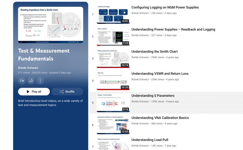
I found a great resource for learning about test and measurement on Rohde Schwarz’s YouTube channel. Each video is about 5 to 15 minutes long and covers the basics of RF test equipment, measurement parameters, and definitions.

Rohde Schwarz Test and Measurement Fundamentals

Measuring RF systems is an important part of Broadcast Engineering. Many folks think that RF plants are going away, replaced by all IP content distribution. I disagree; Terrestrial Broadcasting will be around for a while yet. AM and FM radios are still ubiquitous in cars, homes, businesses, etc. There is no other information distribution method that is as simple and robust as over-the-air broadcasts. That is why Federal Emergency Management is still spending money on hardening broadcast facilities.

The Internet and Mobile Data in particular are susceptible to failure in emergencies. Cellular networks were almost useless due to congestion or system outages during the 9/11 attack or a natural disaster such as Hurricane Sandy.

Radio still has a role to play.

As the older Broadcast Engineers retire, there is a dearth of qualified RF specialists who can make accurate measurements on antenna systems, filters, and other transmission system components. There are very few mentoring opportunities, especially in commercial broadcasting. Gone are the days of several engineers on staff, when there was time to teach the younger people some hard-learned lessons. One of the reasons I write this blog is to pass along some of that knowledge to others so that the industry might survive.

RIP Ray; you were a good guy

By now, most have heard of the passing of Ray Topp, publisher of Radio Guide magazine. I was shocked when I first learned about it in the middle of February. The family has decided to cease publishing the magazine, which is understandable, but also a loss for the industry. The goal of Radio Guide was to provide “real-world technical information.” When I wrote an article, I always thought about the various people I worked with over the years and what they were concerned with.

If you have not read the Radio World article: Ray Topp, Publisher of Radio Guide Dies

The last I heard from Ray was the third week in December. He said he had a bout of COVID and there were some complications. He said he was trying very hard to get the January/February 2023 issue done. I sent in my article in early January but never heard anything back, which is unusual. When the publishing date came and went, I thought that perhaps he was still recovering. Unfortunately, that was not so.

My final article for Radio Guide was to be titled: Learning with the Libra VNA

Since it was never published, I figured perhaps some might find it useful.

1001 uses for a NanoVNA

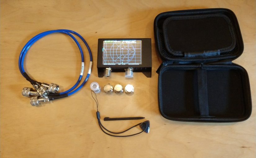
Recently, I pried open my wallet and plunked down the sum of $150.00 for one of these little devices. Now, to be certain, this is not a replacement for a real VNA, especially at a high-power broadcast site. However, it can be used for basic troubleshooting and I have had a good deal of fun fooling around with it.

First, a few quick specifications:

  • Type: SSA-2N NanoVNA V2.2
  • Frequency range: 50 KHz to 3 GHz
  • Power output: -50 to +10 dB
  • Measurement points: 201 (or 1024 with software and computer)
  • Measurement types: S11, S12 and S21
  • Screen Size: 4-inch touch screen
  • Traces: up to 4
  • Battery: 3000mAh Lithium Ion
  • Software OS (VNA-QT): Win 7, Win 10, Linux, MacOS

The unit I purchased came with a small carrying case, calibration loads, and test jumpers. The software is downloadable and easily configured.

What I really like about it is the internal battery and the touch screen.

So what can it be used for?

  • Test a coaxial cable
  • Measure the length of a coaxial cable
  • Figure out what frequency an antenna is designed for
  • Tune a 1/4 wave stub to make a notch filter
  • Measure the characteristics of a crystal/holder
  • Measure a capacitor
  • Measure an inductor
  • Tune a parallel resonant LC circuit to make a notch filter
  • Tune a filter can
  • Test a high pass, low pass or band pass filter
  • Sweep an antenna (Simple AM, FM, RPU, STL, WiFi)
  • Check isocouplers for proper circuit functioning
  • Etc

Pretty much anything you need to know about RF antennas, filters, and transmission lines can be learned with a VNA. One thing to keep in mind; the measurement points are limited, especially in the stand-alone mode. Thus, the smaller the frequency span, the better the measurement resolution will be.

What is this antenna for?
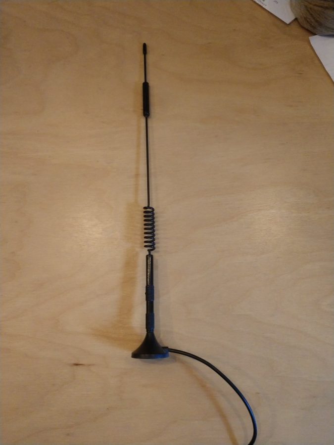
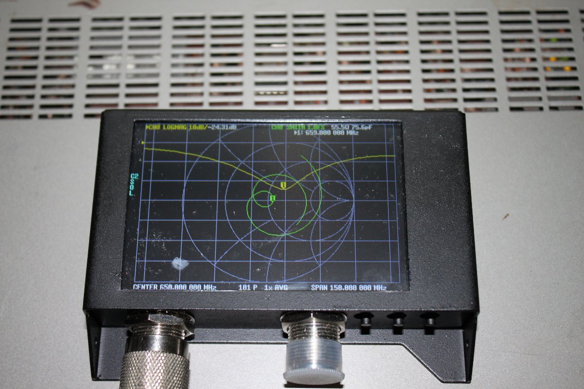
Antenna under test, 659 MHz center frequency

While this is a very inexpensive device designed mainly for Amateur Radio, it can be useful to diagnose antenna and transmission line problems. Would I depend on it to make precise measurements? No. Especially things required by the FCC like base impedance measurements on an AM tower or channel filter measurements for a TV station. Would it work at a high RF transmitter site with multiple AM/FM/TV transmitters? No and chances are you might burn out the front end. Those types of things are best done with professional equipment that has much better accuracy and resolution.

It is a pretty good little tool for basic troubleshooting. One can look at the individual components of an AM ATU for example, or measure the input impedance to see if there has been a shift (should normally be 50 ohms). It is small enough that it can be included in a basic tool kit. It is self-powered. Not bad at all for the price.