1001 uses for a NanoVNA

Recently, I pried open my wallet and plunked down the sum of $150.00 for one of these little devices. Now, to be certain, this is not a replacement for a real VNA, especially at a high-power broadcast site. However, it can be used for basic troubleshooting and I have had a good deal of fun fooling around with it.

First, a few quick specifications:

  • Type: SSA-2N NanoVNA V2.2
  • Frequency range: 50 KHz to 3 GHz
  • Power output: -50 to +10 dB
  • Measurement points: 201 (or 1024 with software and computer)
  • Measurement types: S11, S12 and S21
  • Screen Size: 4-inch touch screen
  • Traces: up to 4
  • Battery: 3000mAh Lithium Ion
  • Software OS (VNA-QT): Win 7, Win 10, Linux, MacOS

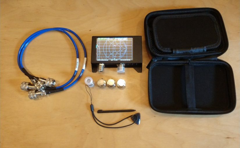
The unit I purchased came with a small carrying case, calibration loads, and test jumpers. The software is downloadable and easily configured.

What I really like about it is the internal battery and the touch screen.

So what can it be used for?

  • Test a coaxial cable
  • Measure the length of a coaxial cable
  • Figure out what frequency an antenna is designed for
  • Tune a 1/4 wave stub to make a notch filter
  • Measure the characteristics of a crystal/holder
  • Measure a capacitor
  • Measure an inductor
  • Tune a parallel resonant LC circuit to make a notch filter
  • Tune a filter can
  • Test a high pass, low pass or band pass filter
  • Sweep an antenna (Simple AM, FM, RPU, STL, WiFi)
  • Check isocouplers for proper circuit functioning
  • Etc

Pretty much anything you need to know about RF antennas, filters, and transmission lines can be learned with a VNA. One thing to keep in mind; the measurement points are limited, especially in the stand-alone mode. Thus, the smaller the frequency span, the better the measurement resolution will be.
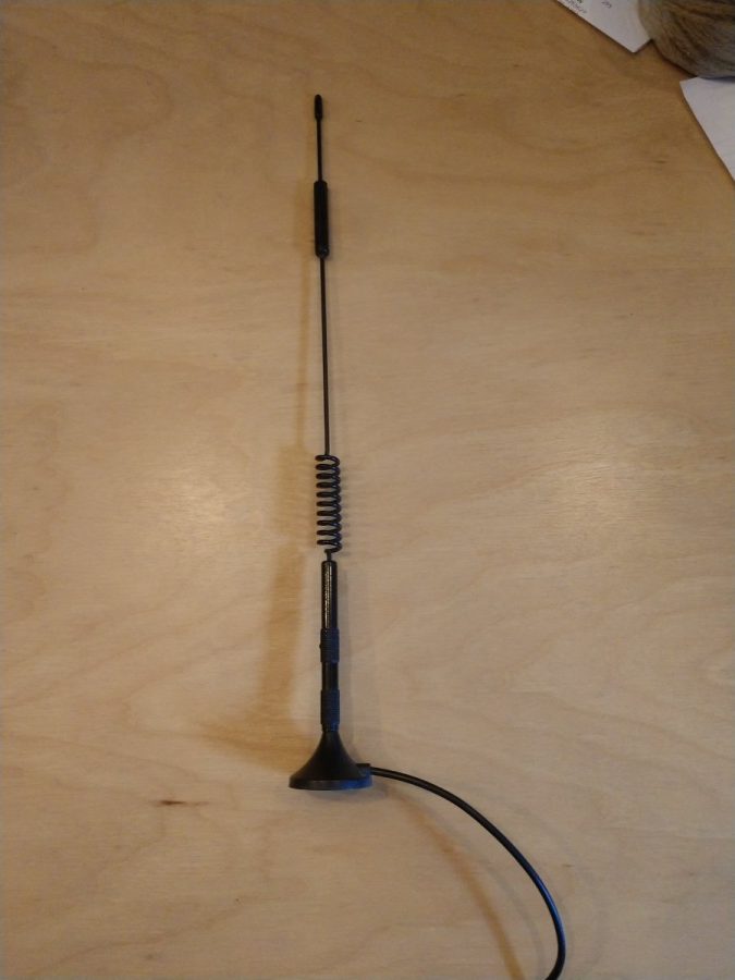
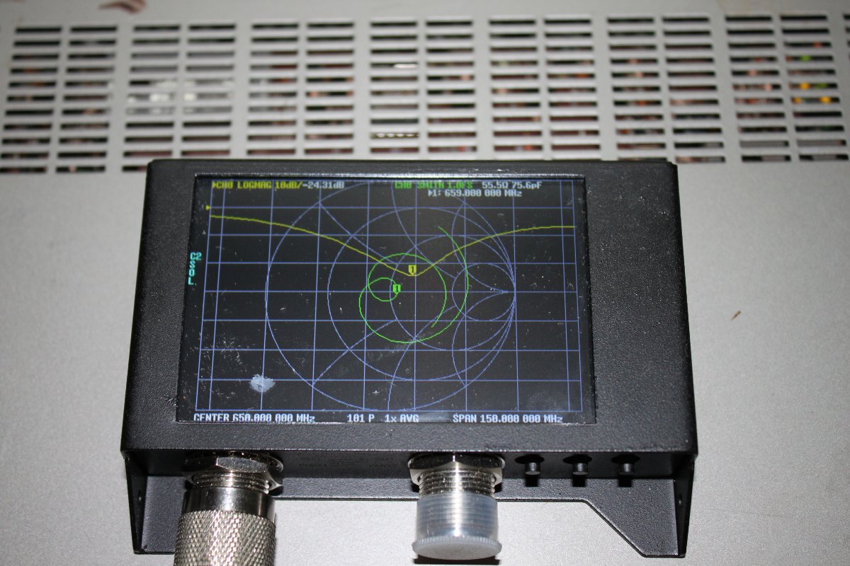
What is this antenna for?
Antenna under test, 659 MHz center frequency

While this is a very inexpensive device designed mainly for Amateur Radio, it can be useful to diagnose antenna and transmission line problems. Would I depend on it to make precise measurements? No. Especially things required by the FCC like base impedance measurements on an AM tower or channel filter measurements for a TV station. Would it work at a high RF transmitter site with multiple AM/FM/TV transmitters? No and chances are you might burn out the front end. Those types of things are best done with professional equipment that has much better accuracy and resolution.

It is a pretty good little tool for basic troubleshooting. One can look at the individual components of an AM ATU for example, or measure the input impedance to see if there has been a shift (should normally be 50 ohms). It is small enough that it can be included in a basic tool kit. It is self-powered. Not bad at all for the price.

Hot Elbow

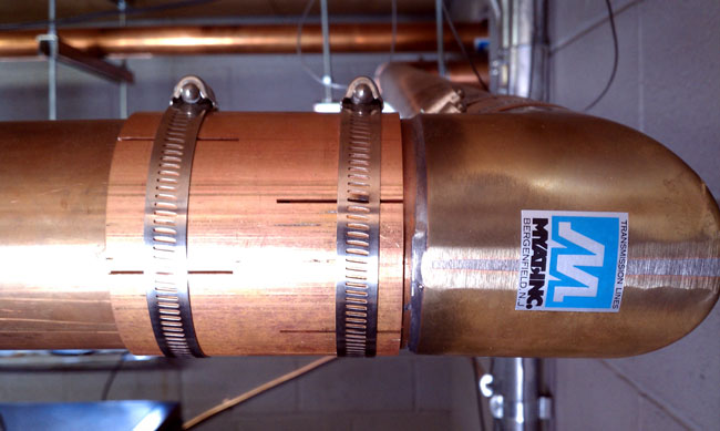
Found this 3-inch rigid elbow to be a little warm when we were removing a dividing wall as a part of an AC upgrade:

MYAT 3 inch elbow
MYAT 3 inch elbow

As measured with my Fluke 62 mini IR thermometer, the temperature is 163°F (72.7°C) at the clamp and drops down in both directions.

This is at WEBE and this particular section of the transmission line is running 34 KW into the analog/digital combiner in the next room.  The clamps are tight, but you can see a little scorch mark on the stainless steel clamp right over the slot in the field flange.  That is where there is a gap between the outer conductors, which possibly means the inner conductor was cut slightly too long during installation.  I suspect this and or a problem with the bullet is causing the heating issue.  I was never (and still am not) a fan of those field flange-type elbows, I’d much prefer the flanged type with a field flange on the straight line section.

34 KW is getting into the semi-serious power level for FM broadcasting.  At those levels, even small impedance mismatches can lead to big problems.  We have a new elbow, field flanges, and bullets on order.  Unfortunately, we will have to take the station off the air to replace this.

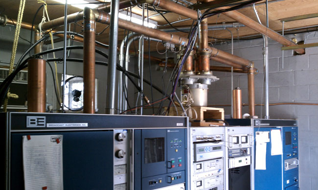
WEBE transmitter site with partition removed

This is all a part of an air conditioning project. There was a plywood partition wall between the front and the back of the transmitters which was impeding airflow.  All of the HVAC contractors who bid on the AC job identified it as a problem that needed to be addressed before the big 5-ton wall-mount AC units were installed.

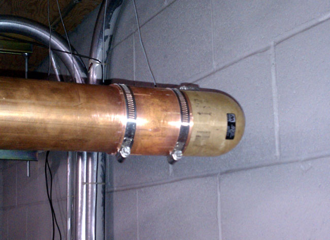
Update: Replaced elbow last night (8/4).  Went off at 10 pm and back on at 10:25.  Found the inner conductor had been pushed out of place and was off center on the outside (toward the wall side) of the elbow.  This was an older elbow that did not have the nylon inner spacers on the center conductor.  The inner conductor was dark purple.  Before replacement, the elbow was 138°F (59°C) under full power (34 KW).  After replacement, it was 97°F (36°C) as was the rest of the transmission line.  At these power levels and frequencies, even small, minor imperfections cause impedance shifts and become issues.

Myat 3 1/8 inch elbow

I cleaned up and reused the bullets and the outer conductor with scotch brite. I also used more support wires because I believe the elbow was starting to pull apart, which can sort of be seen in the first picture.