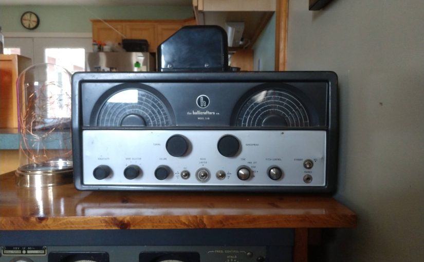
I read with interest the Radio World Article: Why reviving Shortwave is a non-starter. The main premise of the article is that reviving Shortwave broadcasting to Russia is just wishful thinking. Since I am still in contact with persons in Russia, I figured I would attempt to ask them what they thought about it (without putting them at risk, of course).
The short answer; the opinion by Daniel Robinson and Keith Perron is correct. Shortwave is a non-starter in Russia. I asked a series of questions of my Russian friends and received the following answers:
Question: Do Russians own AM/FM radios?
Answer: Yes, especially those with cars. Most listening to analog AM or FM radio is done in cars and sometimes at work wearing headphones.
Question: How about Shortwave or Longwave sets?
Answer: Amateur radio operators and some hobbyists may own these radios, but not the general population.
Question: Are there any leftover shortwave sets from Soviet times/the cold war period?
Answer: Not likely, and if there are, they probably don’t work. Soviet equipment was not high quality.
Question: What about listening to the radio at home?
Answer: Not very many people do this. Most people watch TV while at home or stream movies.
Question: Where do most people get their news?
Answer: The state media TV services (Russia-1 or Channel-1). A few people may stream news from overseas, although this is getting harder and harder to do. Anyone who does this will likely use a VPN.
Question: How many people can find, download, install, and configure a VPN?
Answer: Mostly young people will do this, but it is getting harder to find VPN apps. They are getting removed from online sources and people are afraid to install them on their mobile devices in case they have interactions with the police. Approximately 10% might be using a VPN.
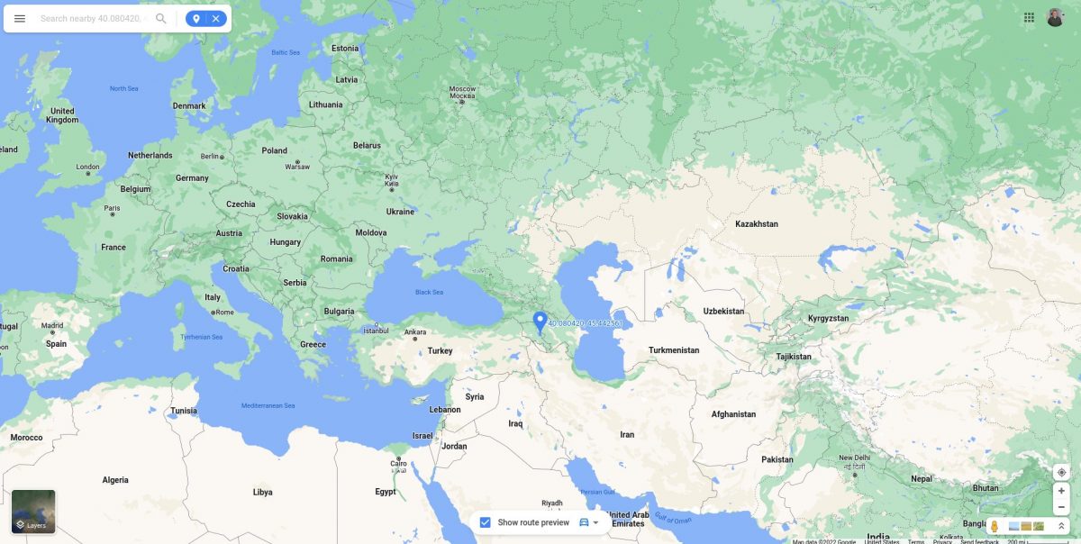
Question: Could Russia disconnect the internet completely from the rest of the world?
Answer: Yes, but it would be difficult. The internet in Russia was not designed to do this the same way as say North Korea or the Great Firewall of China. There are many physical connections out of the country and not everything is well documented. It is much more likely that they will block, censor and track users rather than completely disconnect.
Question: Are there any sources of outside information available in Russia right now?
Answer: For those that are searching for it, yes but likely not for much longer.
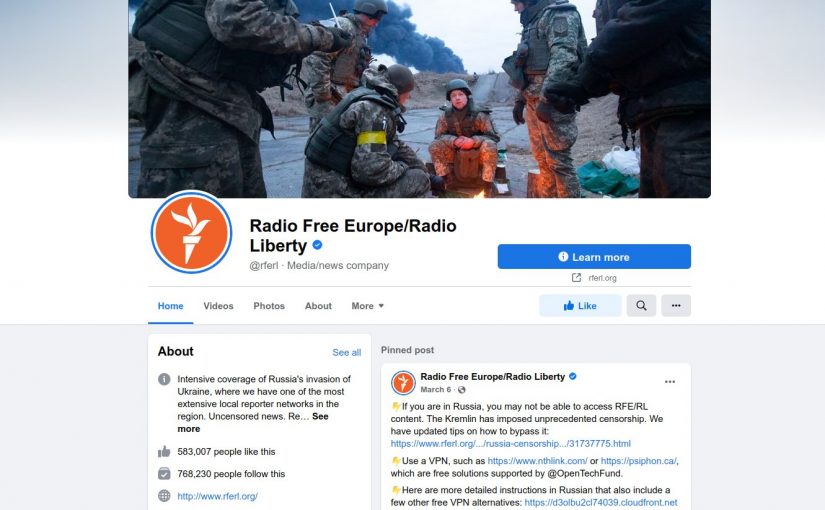
Question: If Radio Free Europe/Radio Liberty were available on AM/FM or Shortwave, would people listen to it?
Answer: No one cares. Unlike during Soviet times, no one really cares about western news or opinion. Things changed in 2014 with the first set of western sanctions. The cultural ministry (Roskomnadzor) began blocking access to internet sites they deemed detrimental. There were few independent media voices left. With the 2016 US election and anti-Russia investigations, most Russians believe that the west is turned against them. The news, as presented on Russia-1 is believed as true.
As a radio professional, I believe in the medium including HF broadcasting. The point of my Russian friends; even if the programs were directly receivable via radio (of any type), most Russian people would ignore them. It is not a technical matter of getting programming to them. It is more a perception problem, brought on by years of propaganda and negative press from the west. If shortwave had been reinstated in 2007 when the first signs of censorship began to appear in Russia, things might be different. Instead, no one seemed to notice or care.
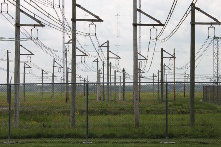
HF broadcasting, like all radio services, can be effective when nothing else works. Much of the VOA’s HF service is targeted to Africa and Cuba, two places that do not have a high percentage of internet users. It is very expensive to build and operate. To revive HF, it will need to get smaller and less expensive. DRM (Digital Radio Mondial) shows promise in this regard, but there is a dearth of available receivers (a quick search on Amazon nets zero usable results). Instead of trying to burn holes through the ionosphere with giant 500 KW AM modulated transmitters coupled to huge antennas with +20 dB gain or more, smaller digitally modulated transmitters with simpler antennas could net the same or better results. If these systems were placed closer to the intended target audience, so much the better.
Clearly, the world has changed. It is time to re-examine (and perhaps update) some of this old technology for 21st-century use. Whatever happens, there are no short, quick, or easy answers. It took decades of time and a momentous effort to bring western ideas to the communist block. This was all undone in a few years by budget cuts.