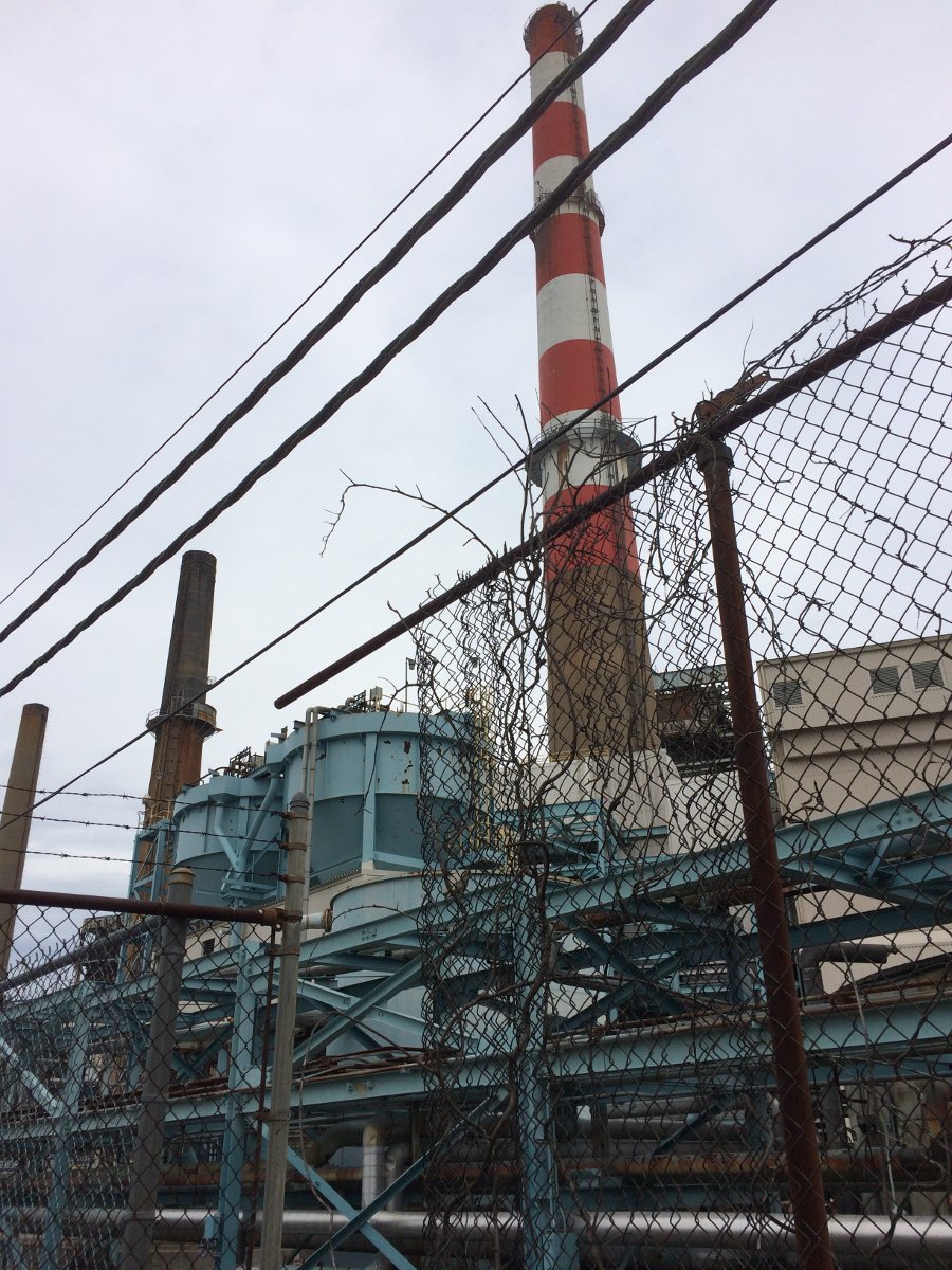
I am currently finishing an interesting project involving putting up two translators on a diplexed AM tower which also holds a mobile phone/data tenant as well. All-in-all, this seems to be a very efficient use of vertical real estate.
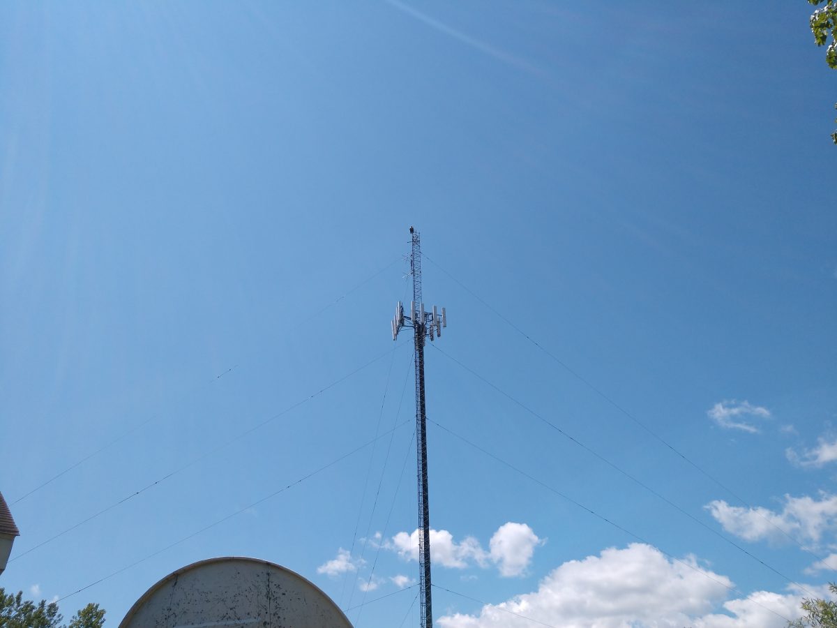
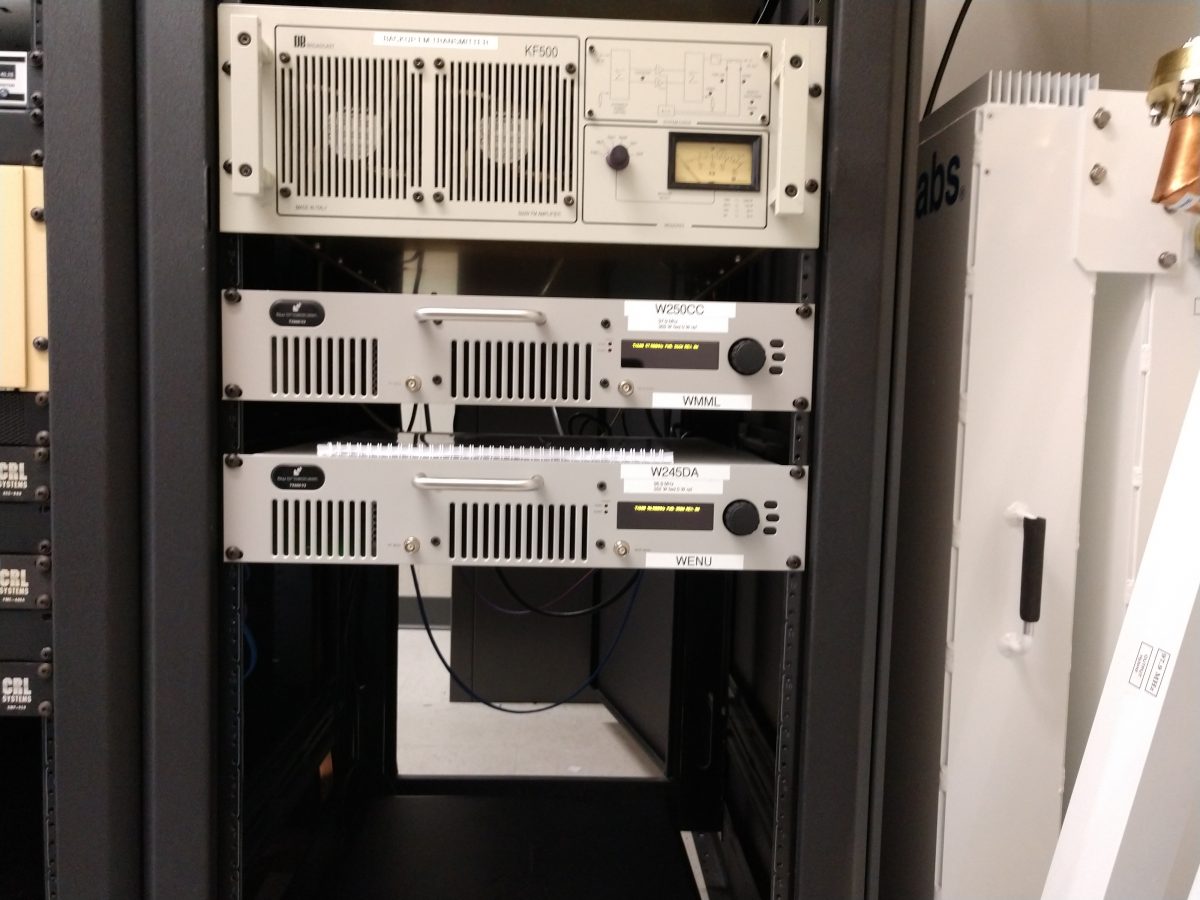
The AM stations are WMML and WENU in Glens Falls, NY. The AM stations are diplexed using a Phasetek diplexor/ATU.
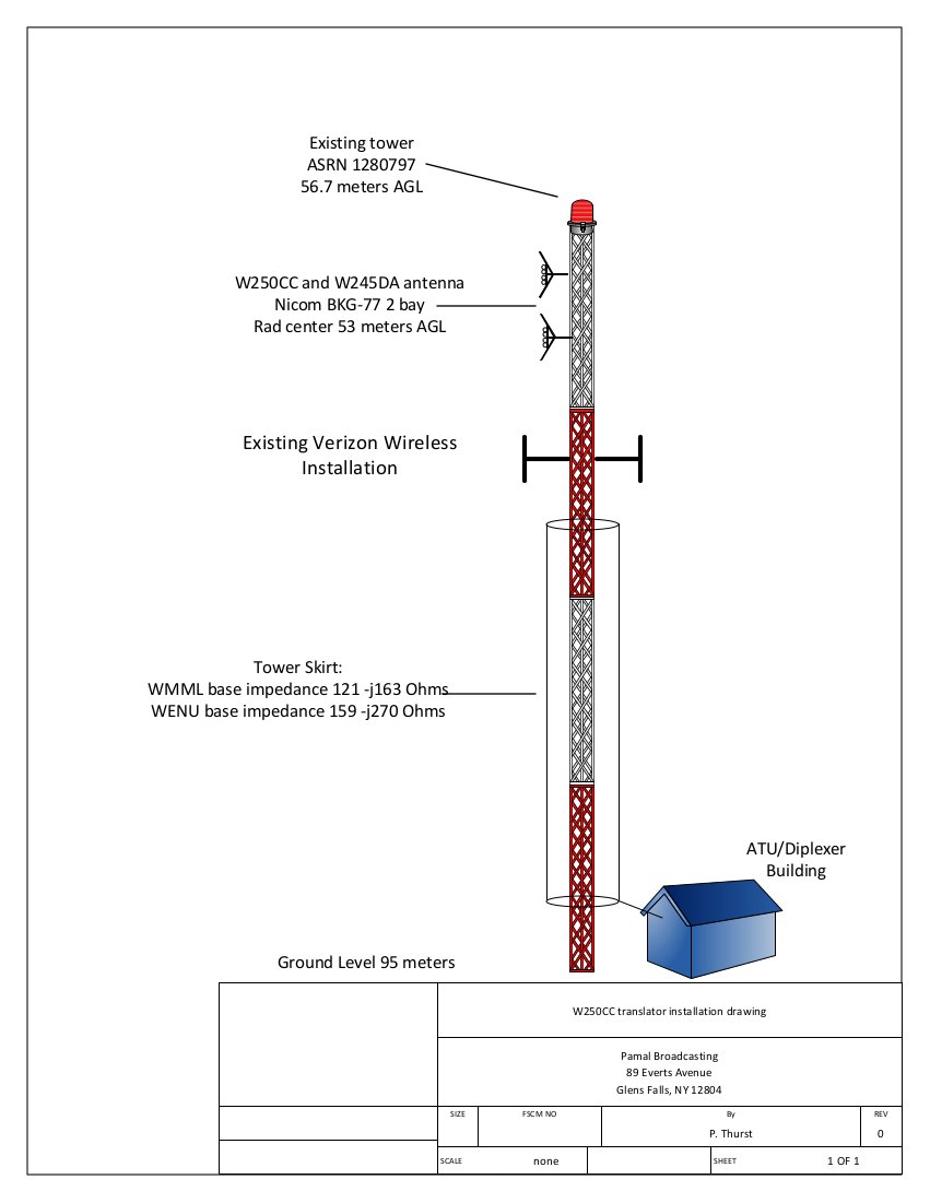

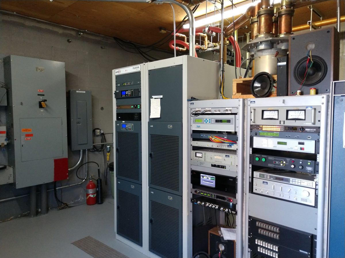
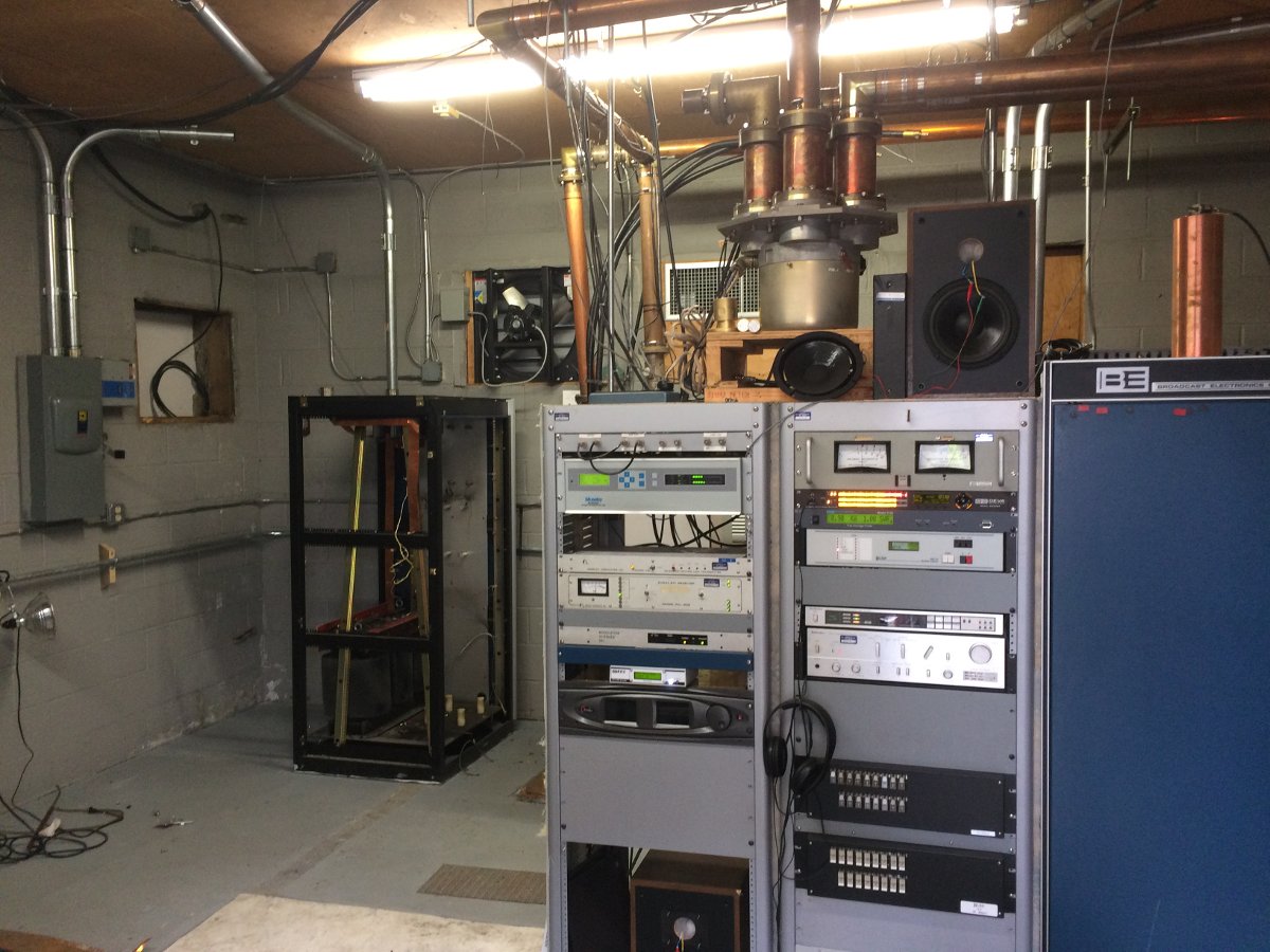
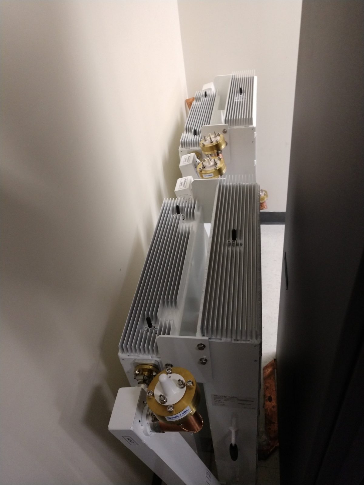
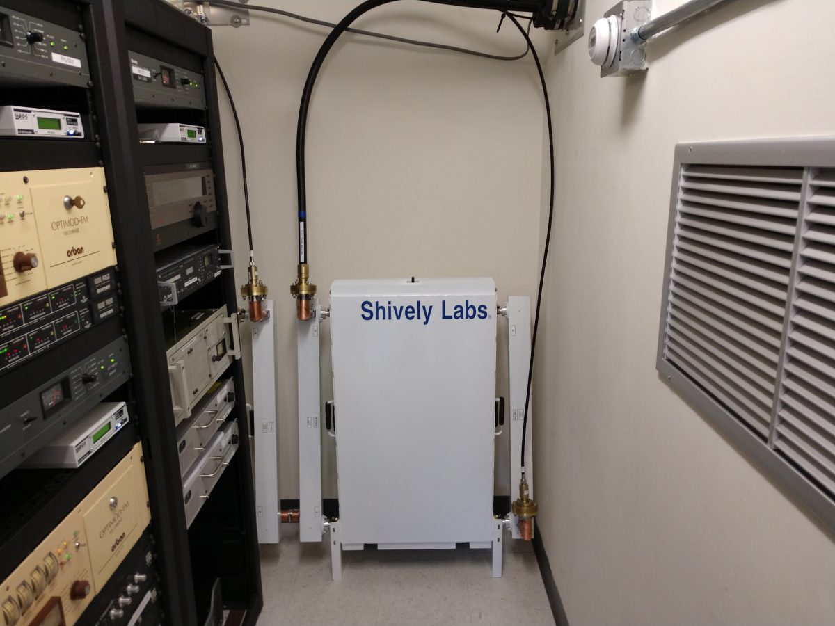
The translators are W250CC and W245DA which are using a NICOM BKG-77/2 two bay 3/4 wave spaced antenna mounted at 53 meters AGL. The translators use a Shively 2640-04/2 filter/diplexor which is a broadband input port in addition to the translator input ports. Since these translator signals are only 1 MHz apart, the higher-power Shively filter was installed because it has better rejection characteristics. The broadband input port allows the NICOM antenna to be used as a backup for any of the three FM stations; WKBE 107.1, WNYQ 101.7, or WFFG 100.3. Two transmitter sites for those stations are mountaintop locations which are very difficult to get to in the wintertime. Having a backup site available takes some of the pressure off during storms or other emergencies.
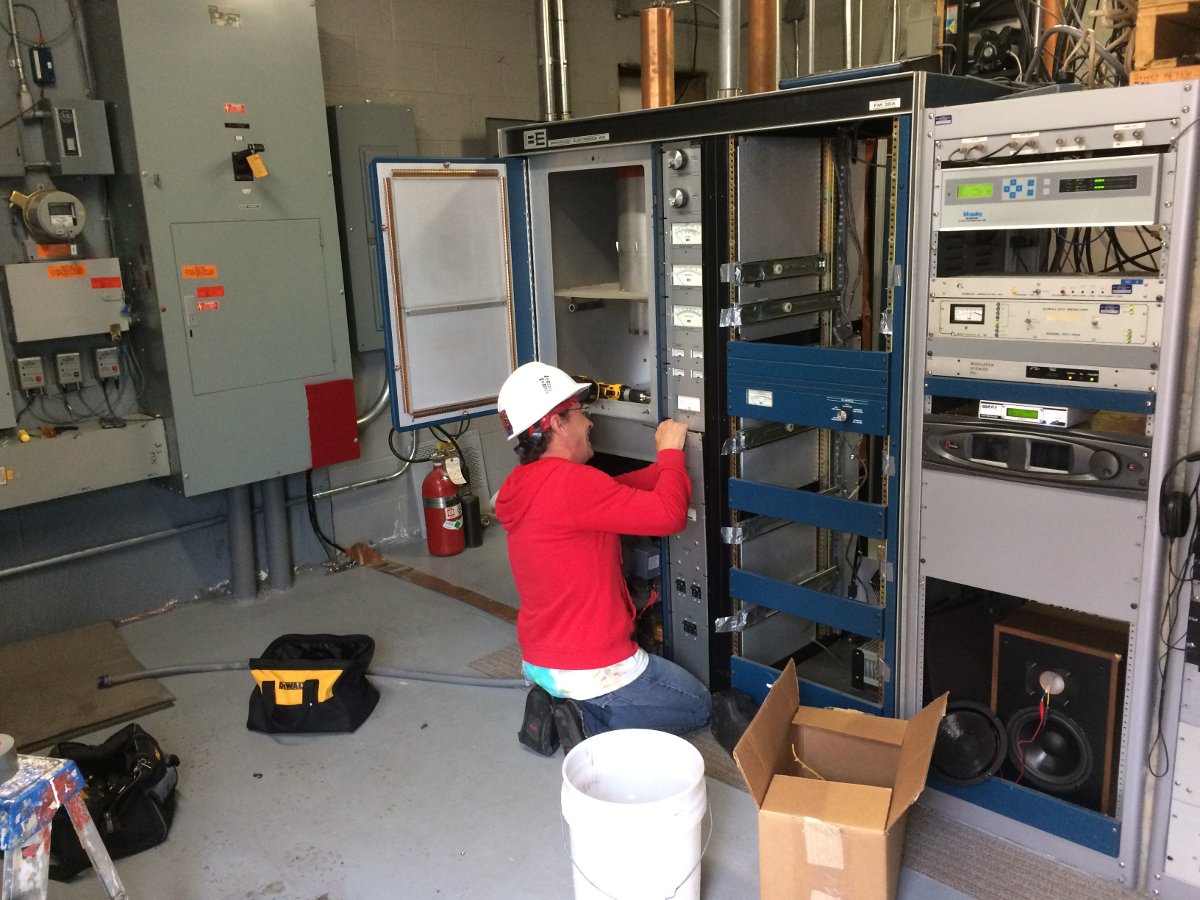
The NICOM FM antenna was mounted on the tower when W250CC went on the air in October 2016. When it was installed, the base impedances for both AM stations were measured. For some reason, WENU 1410 KHz seems to be more sensitive to any changes on the tower, thus the WENU ATU needed a slight touch-up. When working on diplexed AM systems, it is also important to make sure that both trap filters, which are parallel resonant LC circuits, are tuned for maximum rejection of the other signal. During this particular installation, nothing was added to the tower and no change in the base impedance for either station was noted.
As a condition of the construction permit, measurement of spurious emissions of all stations sharing the common antenna needed to be completed to ensure compliance with FCC 73.317(b) and 73.317(d). I made careful measurements of the potential intermod products between the two translator frequencies. This measurement was completed with my TTI PSA6005 spectrum analyzer.
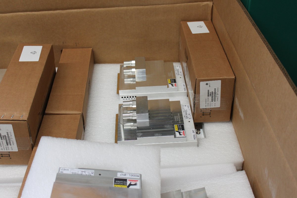
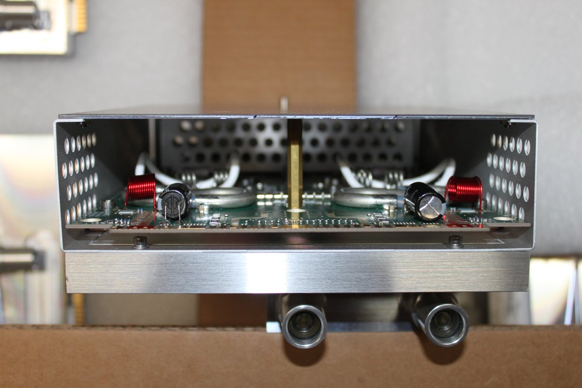
The primary concern here is mixing products between the two transmitters. Both transmitters are BW TXT-600 with low pass filters before the output connector. There are three frequencies of interest;
- (F1 – F2) + F1 or (97.9 MHz – 96.9 MHz ) + 97.9 MHz = 98.9 MHz
- F2 – (F1 – F2) or 96.9 MHz – (97.9 MHz – 96.9 MHz) = 95.9 MHz
- F2 + F1 or 97.9 MHz + 96.9 MHz = 194.8 MHz
That, plus harmonic measurements out to seven or eight harmonics of the fundamental frequency should be enough to demonstrate compliance with FCC out-of-band emissions standards. Being that this site has LTE carriers, it is very important to measure the harmonics in those bands. Mobile data systems often use receiver pre-amps, which can amplify harmonics from the FM band and make them look out of compliance. Having a base set of readings to fall back on is always the best course in case the “out of tolerance” condition gets reported to the FCC.
Measurements on these frequencies must meet the emissions standards outlined in FCC 73.317 (d), which states:
Any emission appearing on a frequency removed from the carrier by more than 600 kHz must be attenuated at least 43 + 10 Log10 (Power, in watts) dB below the level of the unmodulated carrier, or 80 dB, whichever is the lesser attenuation.
Harmonic frequencies to be measured:
| Harmonics for 96.9 MHz fundamental | Harmonics for 97.9 MHz fundamental | Comments |
| 193.8 | 195.8 | |
| 290.7 | 293.7 | |
| 387.6 | 391.6 | |
| 484.5 | 489.5 | |
| 581.4 | 587.4 | |
| 678.3* | 685.3* | US LTE Band 71 |
| 775.2* | 783.2* | US LTE Band 5 |
| 872.1* | 881.1* | US LTE Band 5 |
| 969.0 | 979.0 |
*Frequencies that fall within the mobile data LTE bands. Traces were recorded and saved for these frequencies.
All of that information, once compiled is attached to the FCC form 350-FM, which, once filed grants Program Test Authority.