I have been working on an AM station lately. WBNR signed on in 1959 and follows the now familiar AM trajectory; after making bank in the ’60s, ’70s, and ’80s, revenue declined, maintenance deferred, yada, yada, yada…
After a stint with a news-talk format, the station changed to “Real Country,” a few years ago. WAT! Music on the AM? Actually, it is doing quite well. The perception is that AM sounds terrible and nobody listens to it. The stock AM radio in my Subaru (made by Pioneer) sounds pretty good on AM. I have noticed that when I first tune a station in, it sounds narrow-banded, slightly better than a telephone. However, after a second or two, the bandwidth opens up and it can sound quite good. I have also heard this station playing at several local businesses. When we turn it off to do maintenance, the phone starts ringing. Clearly, somebody is listening…
This station is part of a three-station simulcast. The AM station to the north got rid of its directional antenna and added an FM translator a few years ago. That has made a big difference. Thus a translator was acquired for this station as well.
The translator was held up by an informal objection filed by Prometheus, Et. Al. as part of a blanket filing against all new translator licenses by the LPFM advocate. In any case, the Construction Permit has been on hand for a while, so the owner felt it was time to move forward with building out the new FM signal.

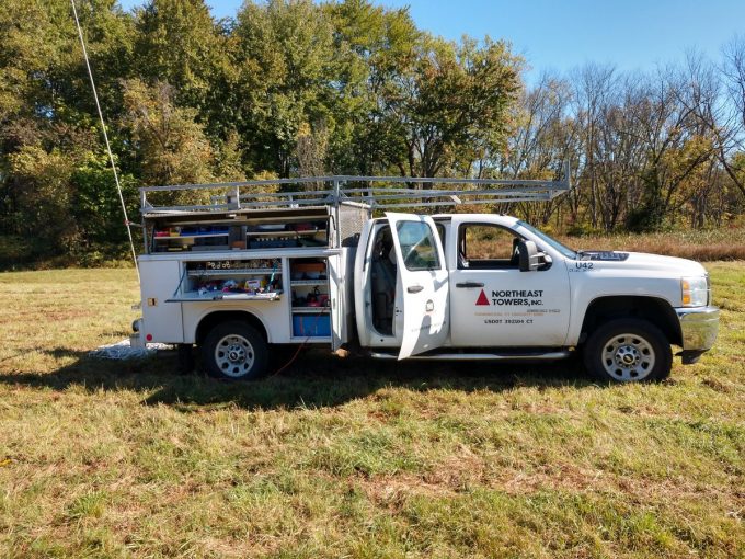
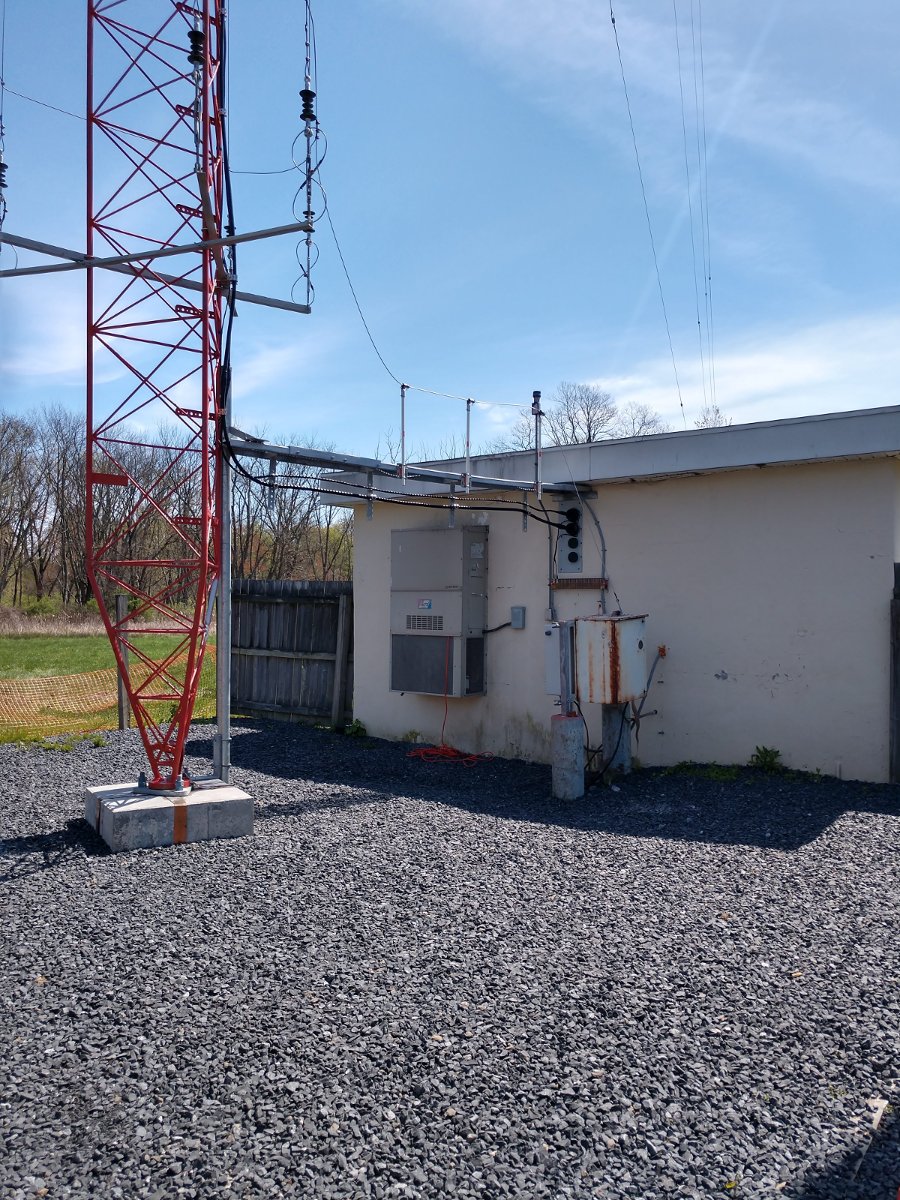
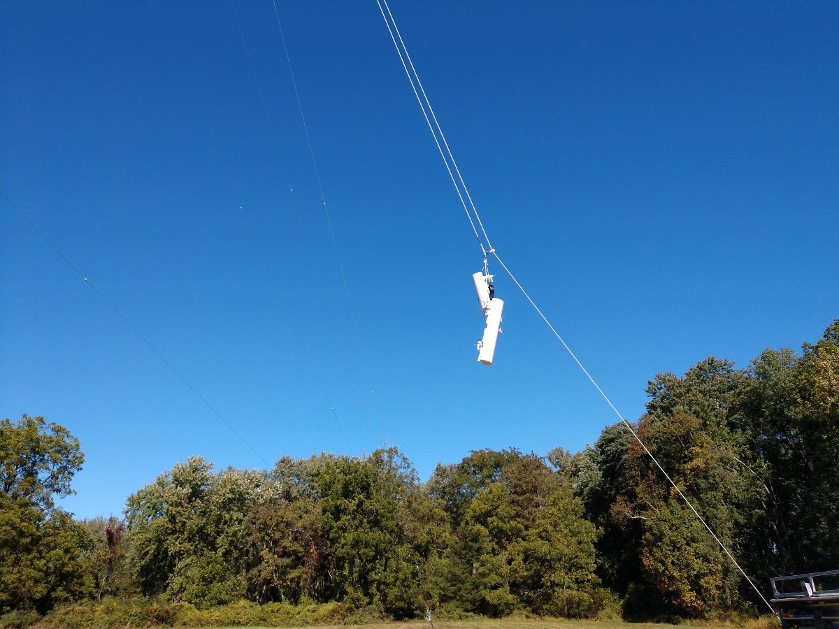
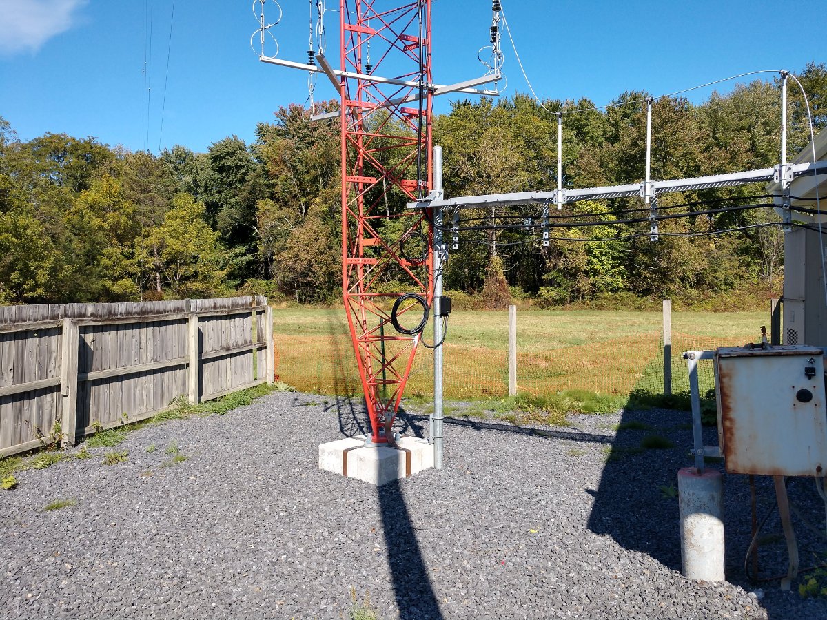
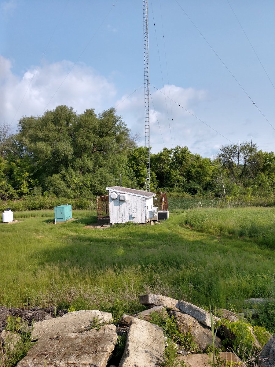
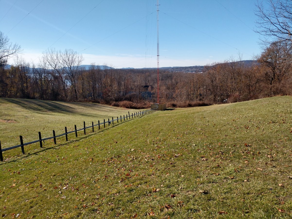
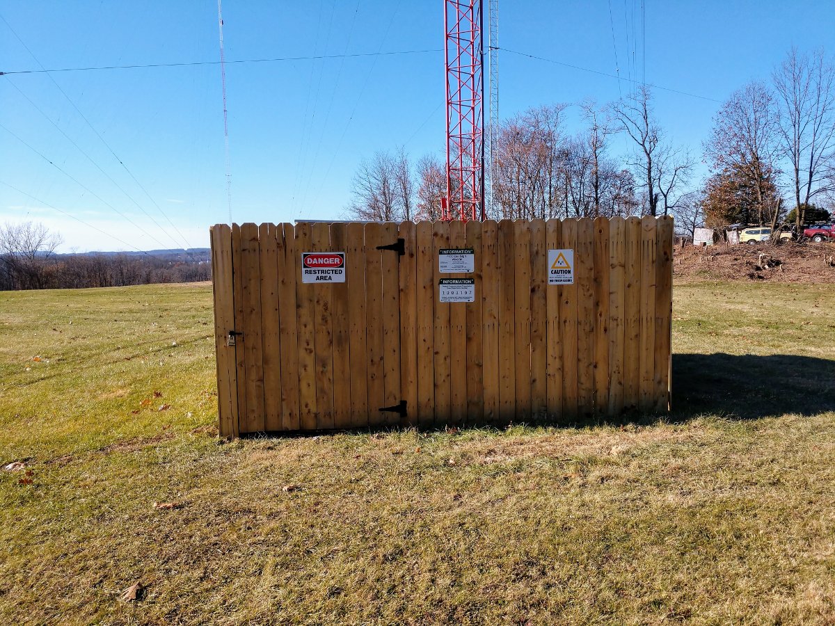
Installing the single-bay Shively 6812 antenna on the side of one of the nighttime towers triggered some other things. A bit of the deferred maintenance was addressed; new stockade fences around all the towers replaced the original fences put up in 1988. Those original fences were falling down.
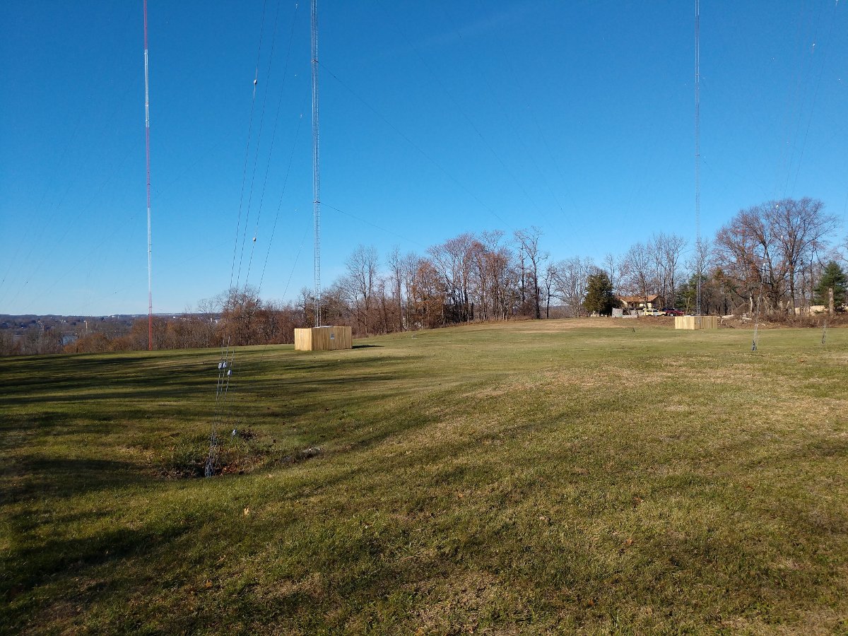
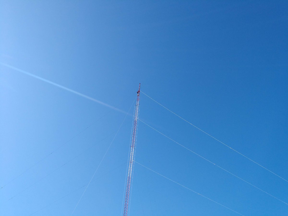
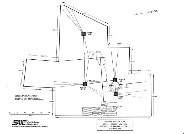
The antenna system for WBNR is actually quite elegant, perhaps even beautiful. A simple two-tower system for the daytime array and a separate two-tower system for the nighttime array. The nighttime towers are top-loaded, adding about 30.7 degrees in electrical height.
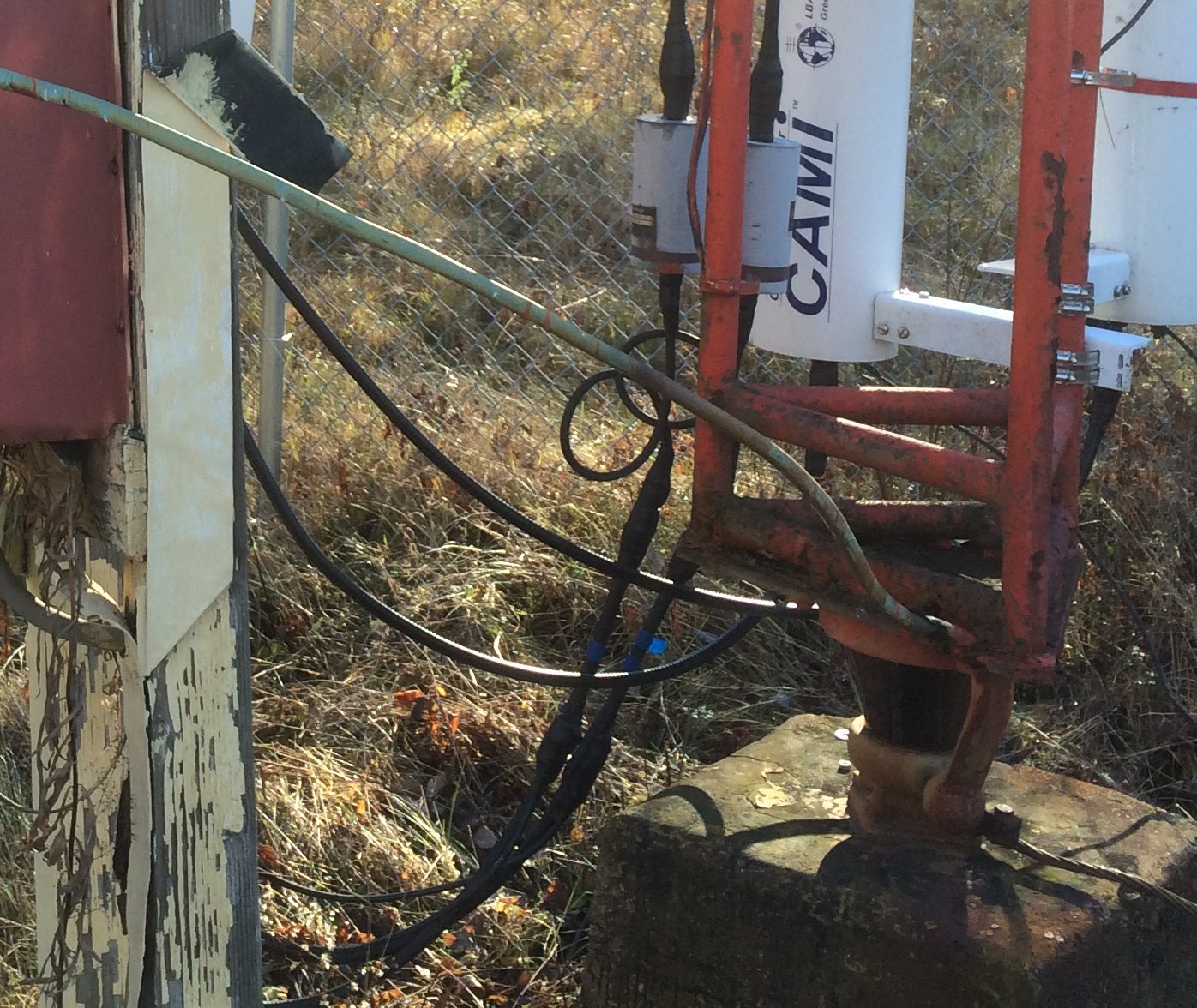
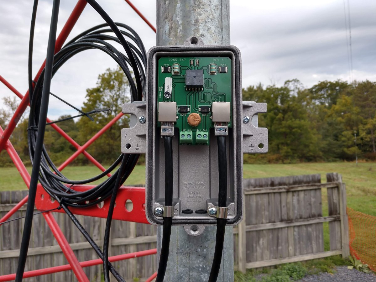
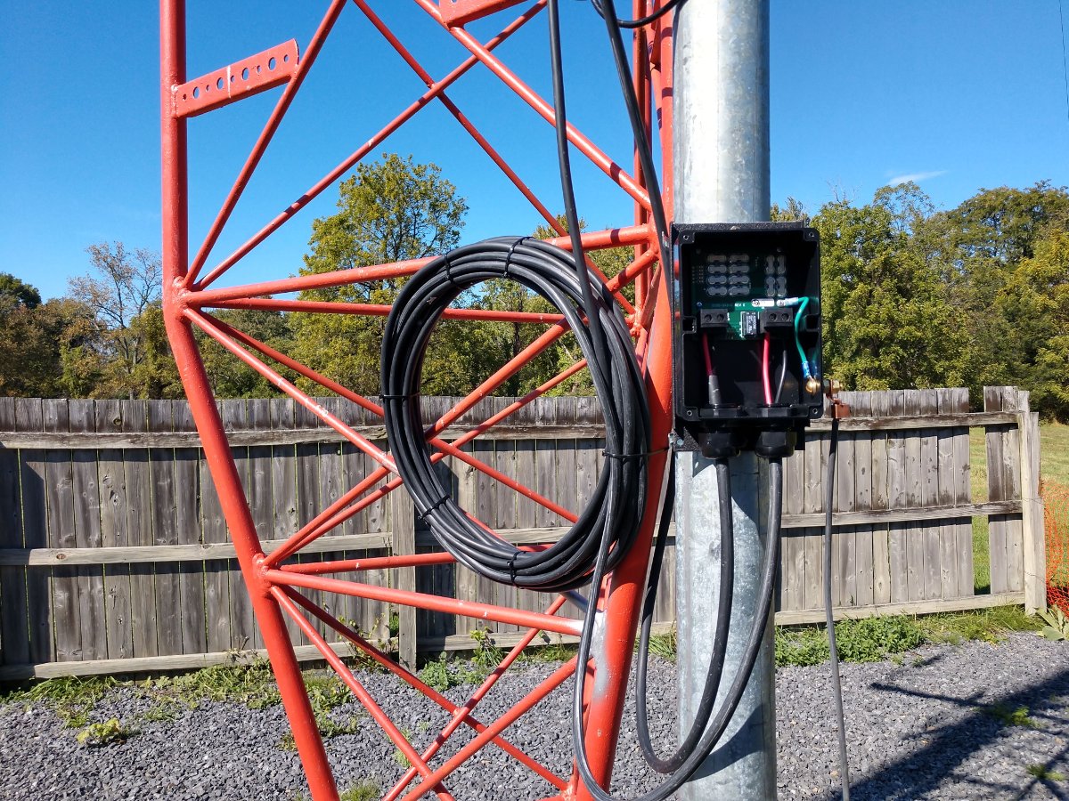
The CP for the translator required some extra steps because of the mounting on the night tower of the AM array. Before and after impedance measurements need to be taken on the tower in question. Another requirement of the CP, is a set of before and after monitor points need to be taken.
While I was measuring the base impedance, I decided to measure all the towers instead of just the nighttime tower that has the translator antenna mounted on it. This is a good point of reference if any problems arise in the future. Often, this information can be found in the technical paperwork from the original license application. Those files can be a treasure trove of information. Unfortunately, it appears that a good portion of the original paperwork is missing.
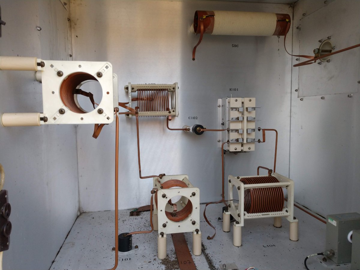
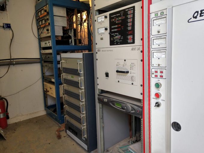
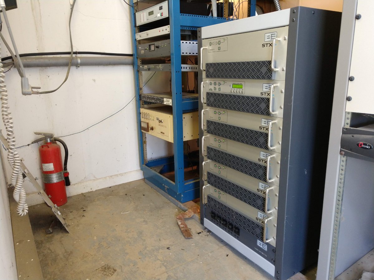
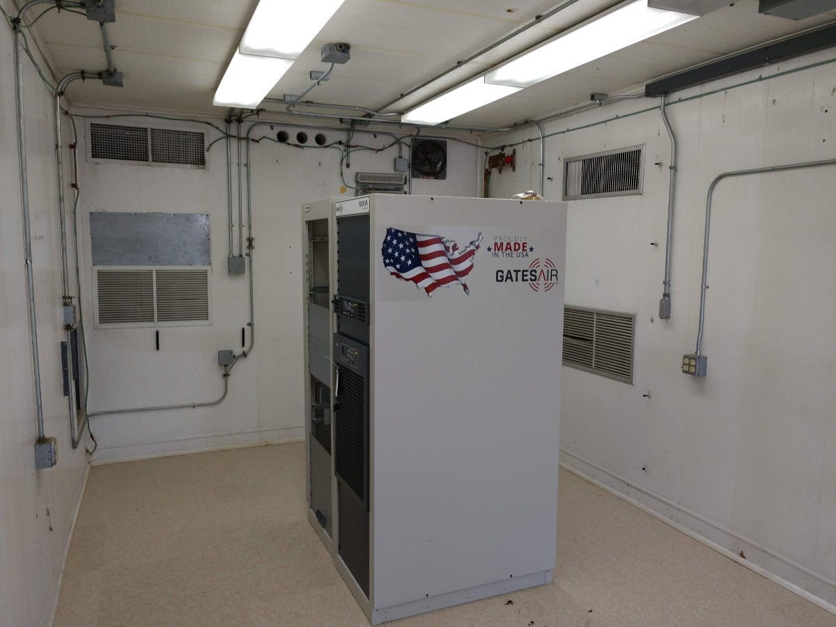
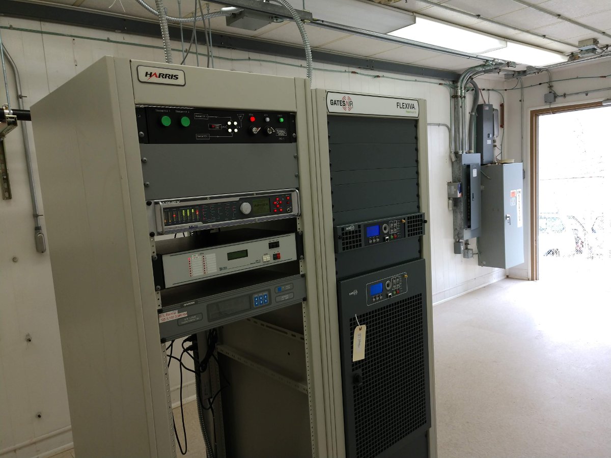
The Phasor and ATUs are a late 80’s Harris product. They are actually in remarkable shape, all things considered. All of the RF contactors are Harris HS-4P motor-driven units. They are rated at 30 Amps, RF-RMS. I don’t think that they are supported by GatesAir. I have a small stock of spare finger stock and contact bars. I suppose, if I had to, I could make or adapt parts to repair.
Looking at the base currents and the base current ratios for both the day and night patterns (base current ratios are on the station license), the tower impedance has changed very little over thirty years. That is good news, especially with those 215-degree-tall nighttime towers.
The WBNR license application did contain an overall system diagram showing the Phasor and all the ATUs. It did not contain any component ids or other information. I scanned that in, created a vector graphics file, and expanded it to a 24 x 36 inch size. I was able to fit all the component values and other information on the diagram.

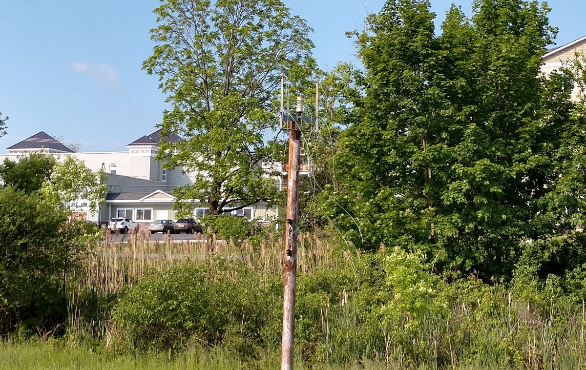
The other issue is the monitor point descriptions. They include statements such as “Point is marked with yellow and white paint on a tree,” or “In the northeast corner of the Texaco research facility parking lot.” Those references are long gone and I would prefer to use a set of GPS coordinates. Using the topographical maps from the proofs, I found each monitor point and then recorded a set of GPS coordinates for each. In the future, they will be much easier to find. If anyone is still doing monitor points, I would recommend this method.
Yet another problem; the phasor control system was damaged by lightning. The overly complicated Harris Phasor control card was replaced with something more straightforward and reliable. I designed a simple set of relays, one for daytime and one for nighttime, to change the antenna system over. The transmitter interlock goes through the relay contacts, so the transmitter PDM is killed while the power changes. Tally back from each of the towers is handled by a set of relays for each pattern, which is also interlocked with the transmitter. All of this prevents the RF contactors from switching hot, something that has caused some damage in the past.
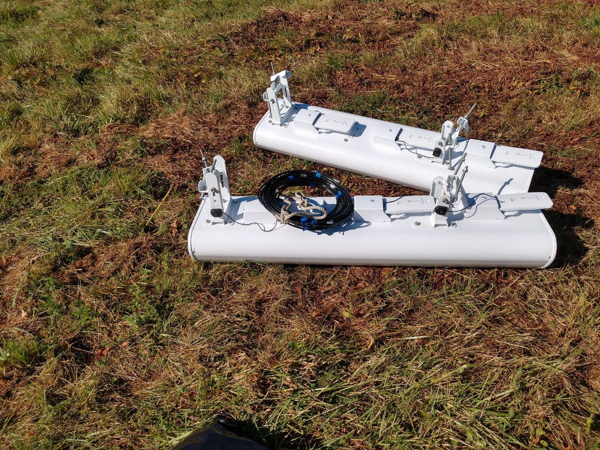
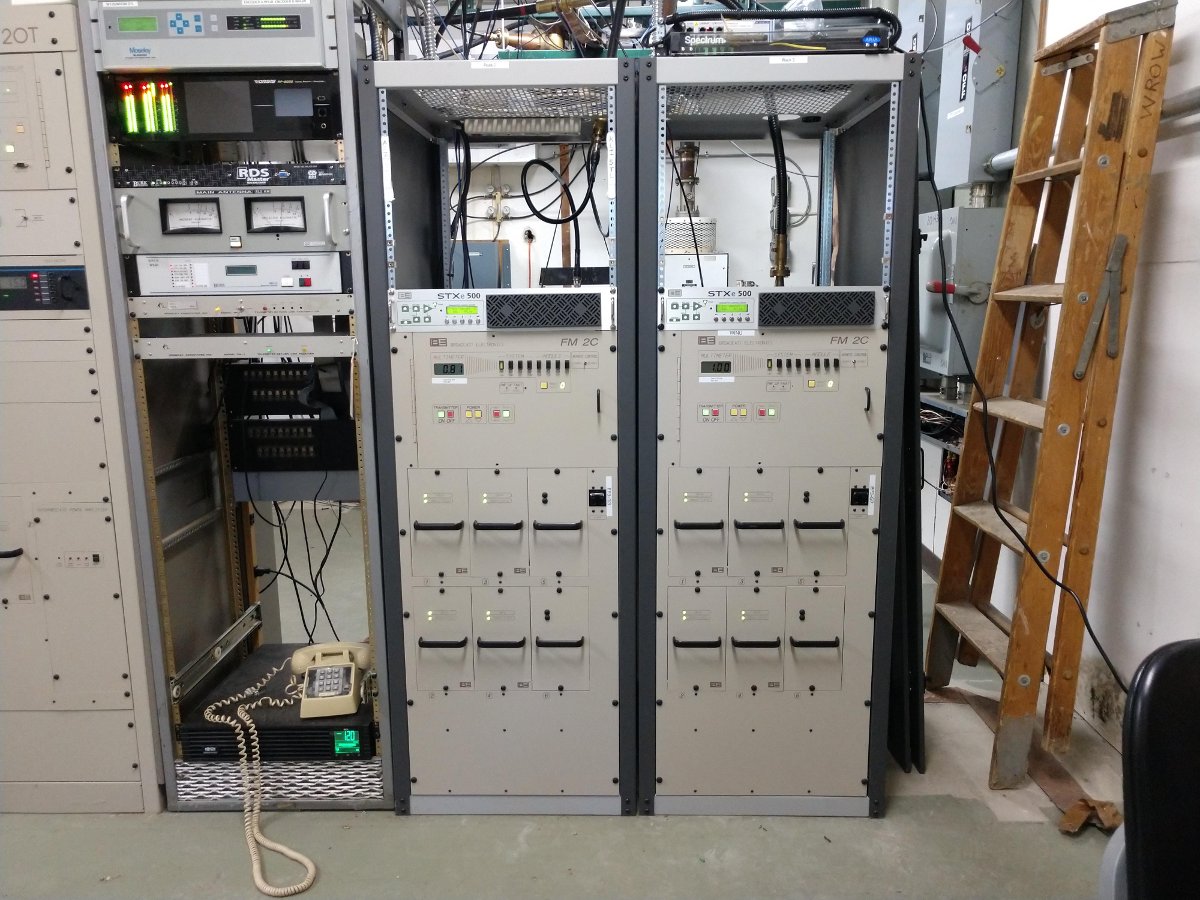
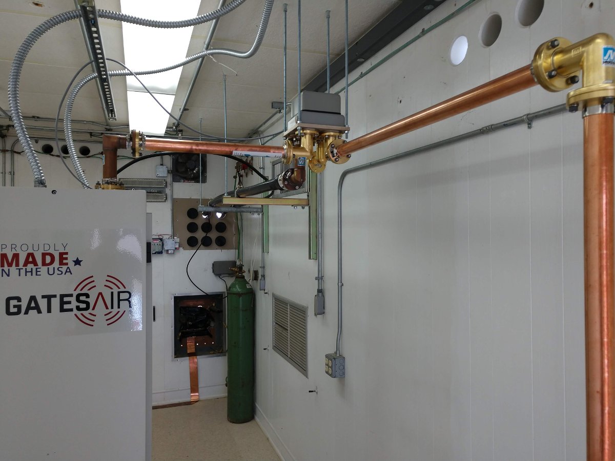
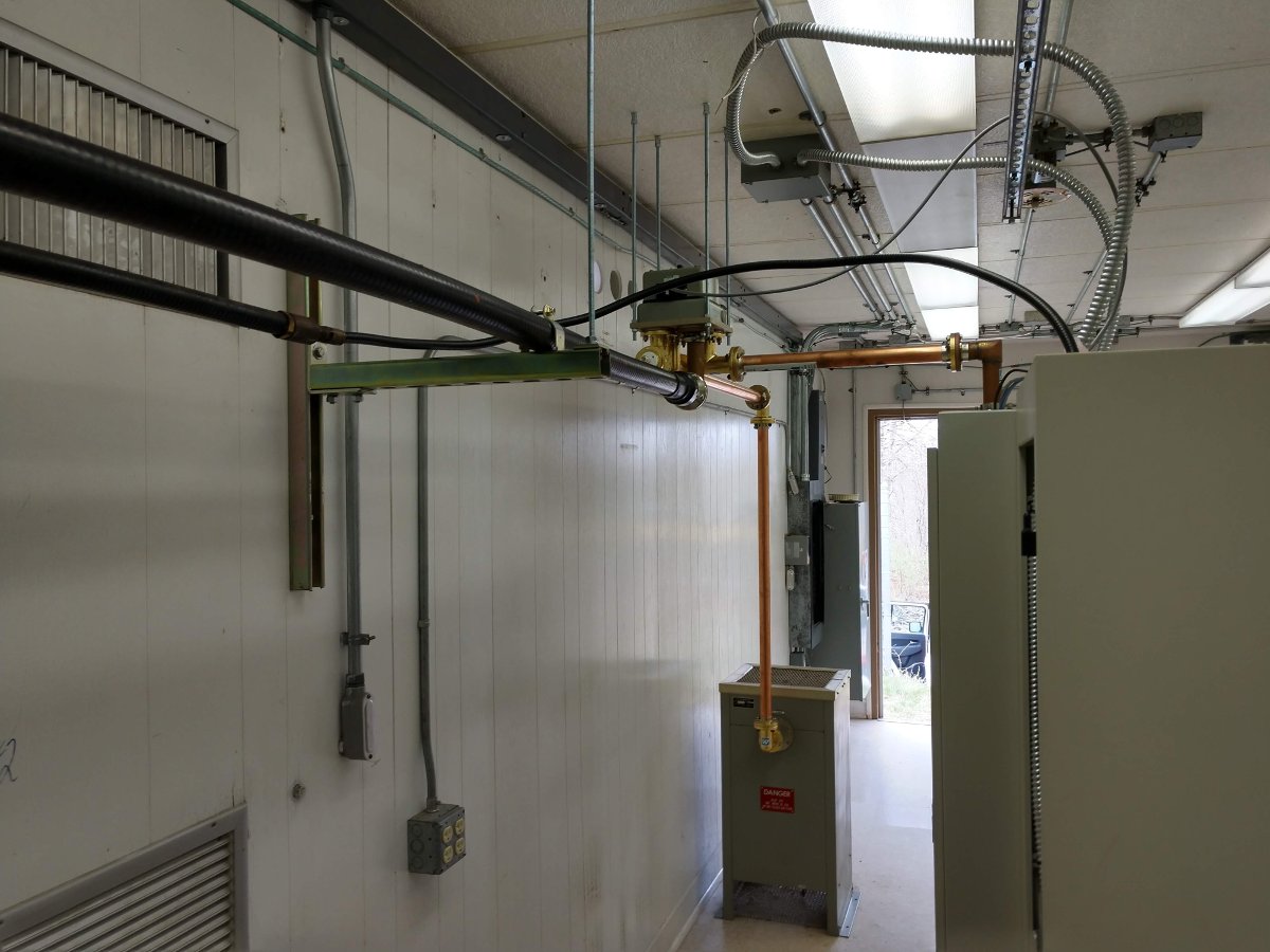
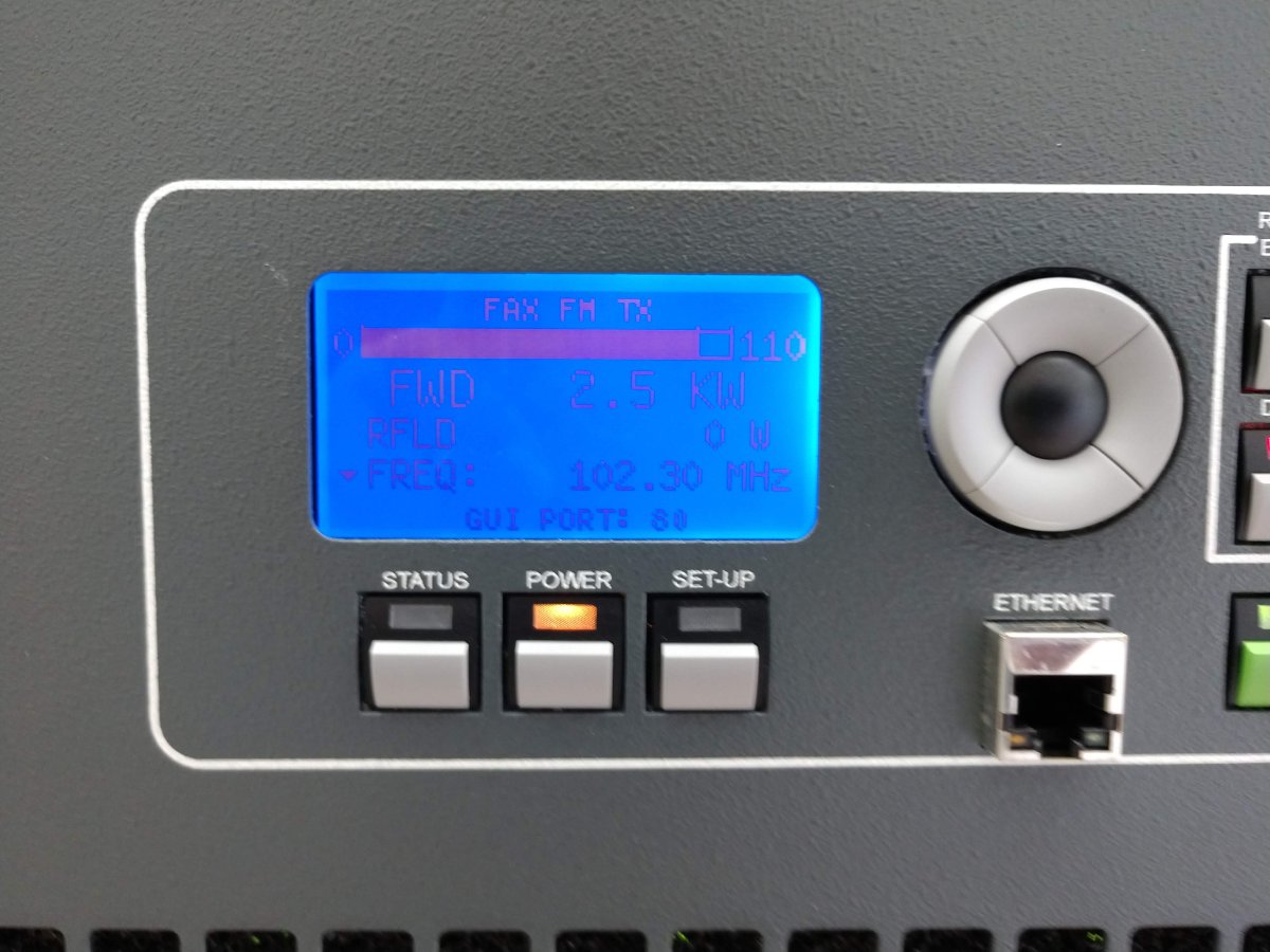
W243EM is 100 ERP watts, non-directional with a 1 bay Shively 6812-1R antenna installed at 381 feet (116 Meters) AGL on one of the nighttime towers.
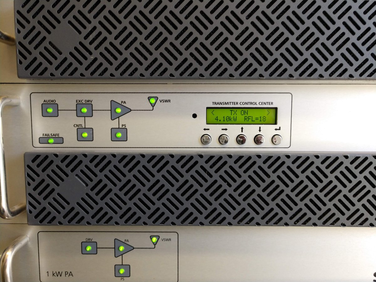
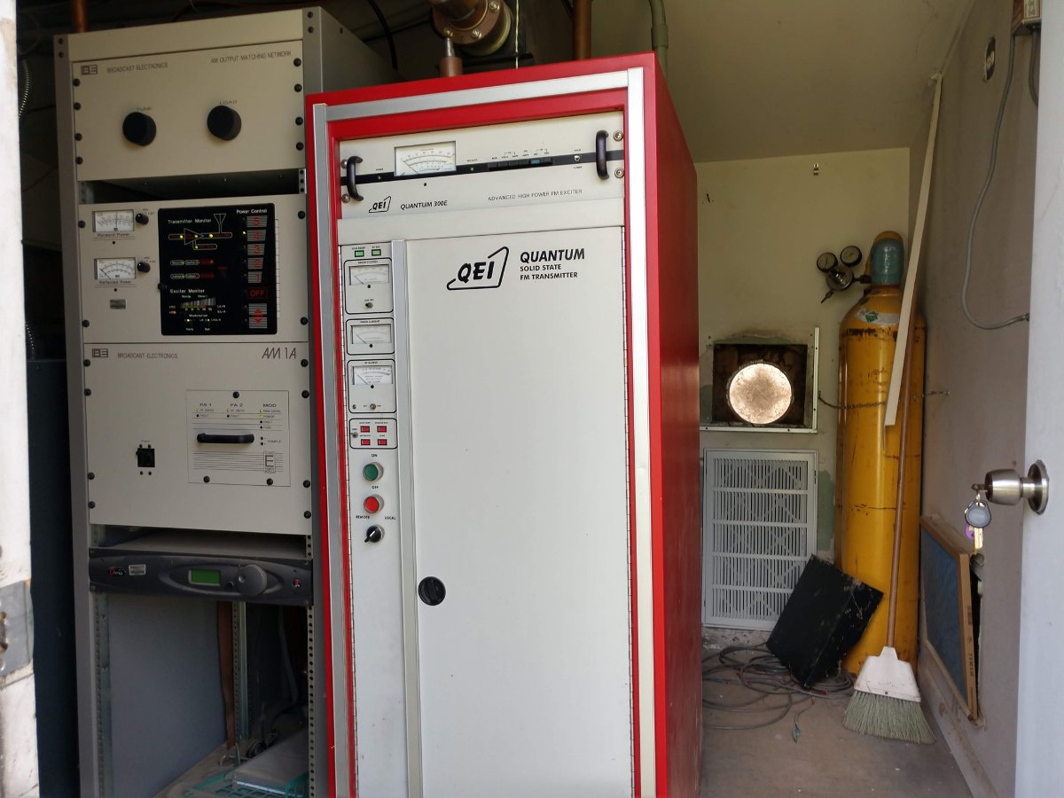
The transmitter is a BW Broadcast TXT-600. The power calculation is as follows: