More AM work

I have been working on an AM station lately.   WBNR signed on in 1959 and follows the now familiar AM trajectory; after making bank in the ’60s, ’70s, and ’80s, revenue declined, maintenance deferred, yada, yada, yada…

After a stint with a news-talk format, the station changed to “Real Country,” a few years ago.  WAT! Music on the AM? Actually, it is doing quite well. The perception is that AM sounds terrible and nobody listens to it.  The stock AM radio in my Subaru (made by Pioneer) sounds pretty good on AM.  I have noticed that when I first tune a station in, it sounds narrow-banded, slightly better than a telephone.  However, after a second or two, the bandwidth opens up and it can sound quite good.  I have also heard this station playing at several local businesses.  When we turn it off to do maintenance, the phone starts ringing.  Clearly, somebody is listening…

This station is part of a three-station simulcast.  The AM station to the north got rid of its directional antenna and added an FM translator a few years ago.  That has made a big difference.  Thus a translator was acquired for this station as well.

The translator was held up by an informal objection filed by Prometheus, Et. Al.  as part of a blanket filing against all new translator licenses by the LPFM advocate.  In any case, the Construction Permit has been on hand for a while, so the owner felt it was time to move forward with building out the new FM signal.

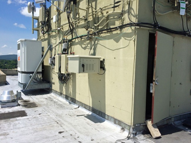
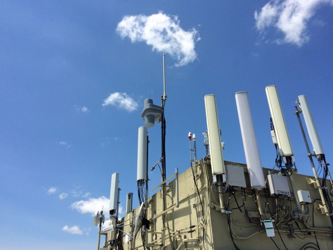
Hoisting the Shively 6812 antenna

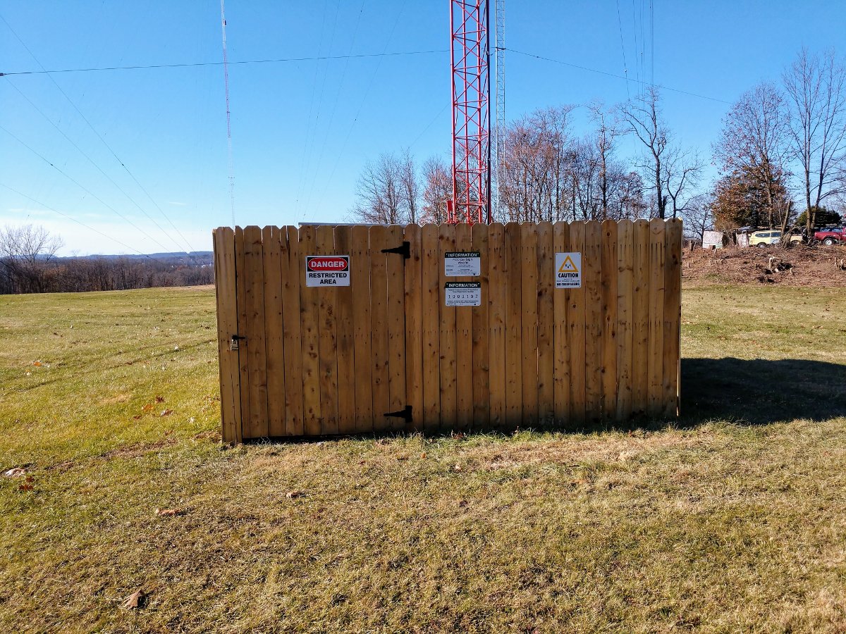
Installing the single-bay Shively 6812 antenna on the side of one of the nighttime towers triggered some other things.  A bit of the deferred maintenance was addressed;  new stockade fences around all the towers replaced the original fences put up in 1988. Those original fences were falling down.
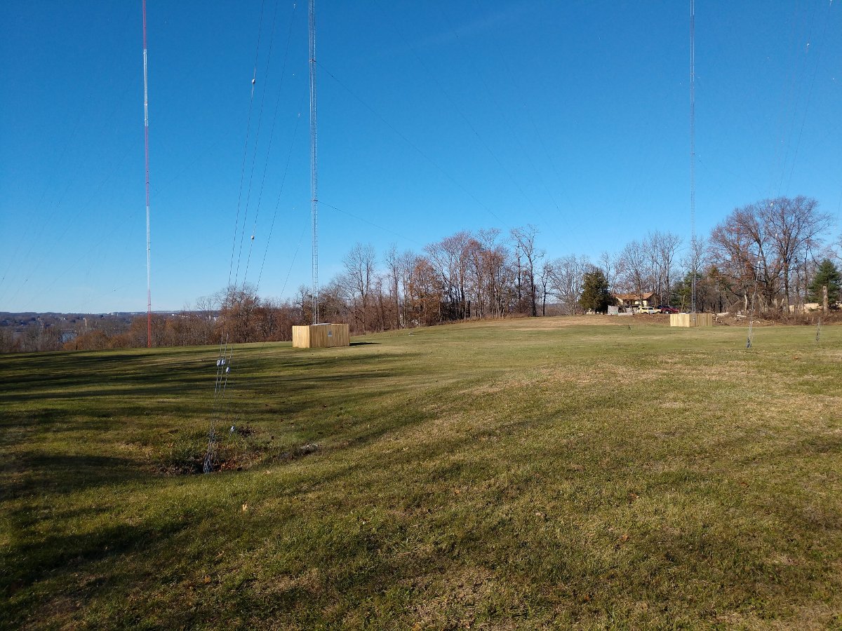
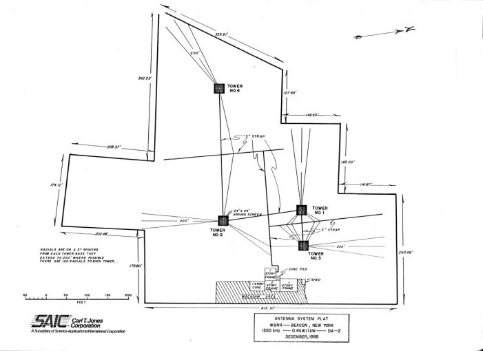
4 Tower antenna system, WBNR, Beacon, NY

The antenna system for WBNR is actually quite elegant, perhaps even beautiful.  A simple two-tower system for the daytime array and a separate two-tower system for the nighttime array.  The nighttime towers are top-loaded, adding about 30.7 degrees in electrical height.
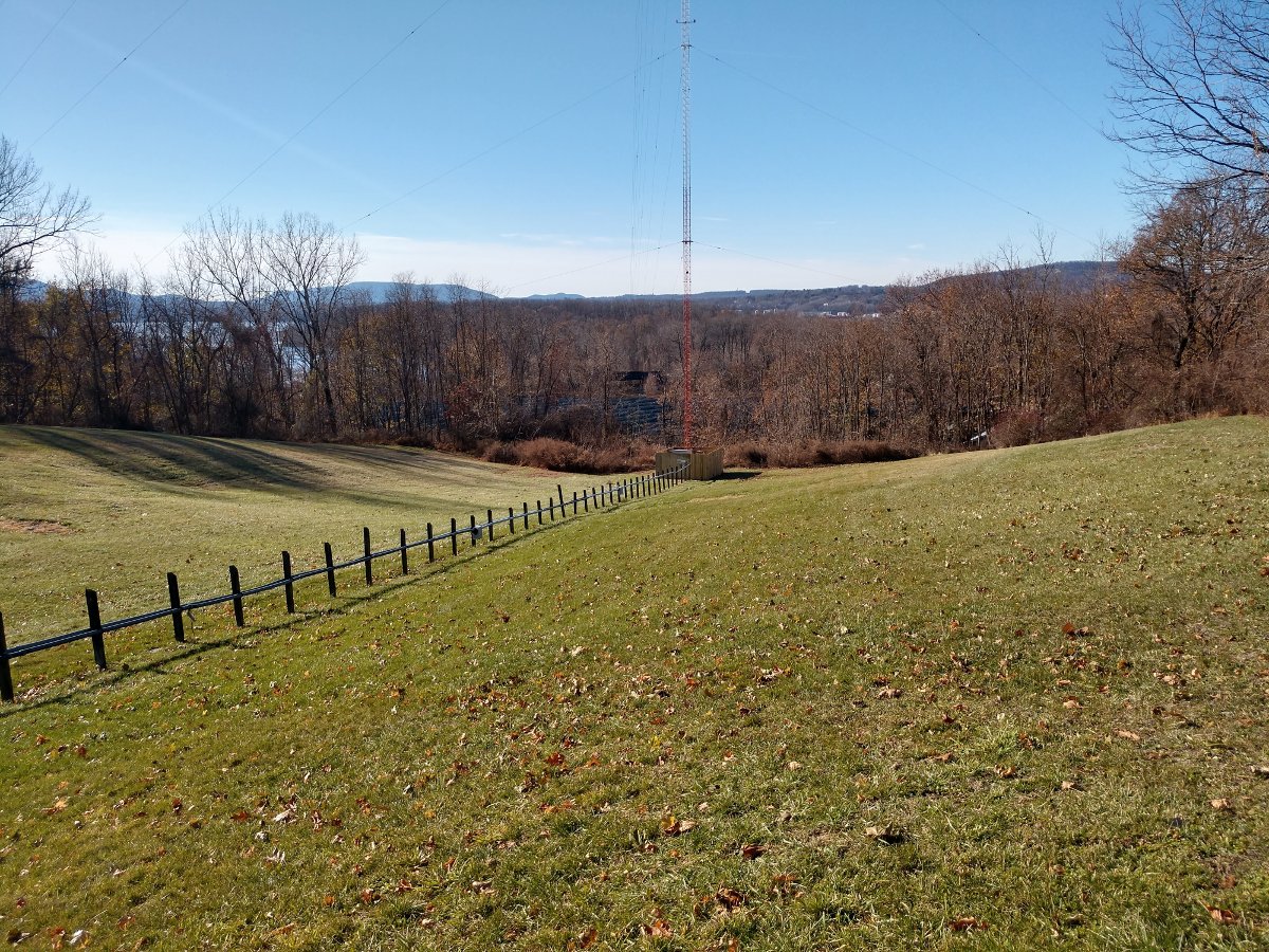
The far tower
The far tower

The CP for the translator required some extra steps because of the mounting on the night tower of the AM array.  Before and after impedance measurements need to be taken on the tower in question.  Another requirement of the CP, is a set of before and after monitor points need to be taken.
WBNR tower, with translator antenna side mounted at 390 feet AGL
WBNR tower, with translator antenna side mounted at 381 feet (116 Meters) AGL

While I was measuring the base impedance, I decided to measure all the towers instead of just the nighttime tower that has the translator antenna mounted on it.  This is a good point of reference if any problems arise in the future.  Often, this information can be found in the technical paperwork from the original license application.  Those files can be a treasure trove of information.  Unfortunately, it appears that a good portion of the original paperwork is missing.
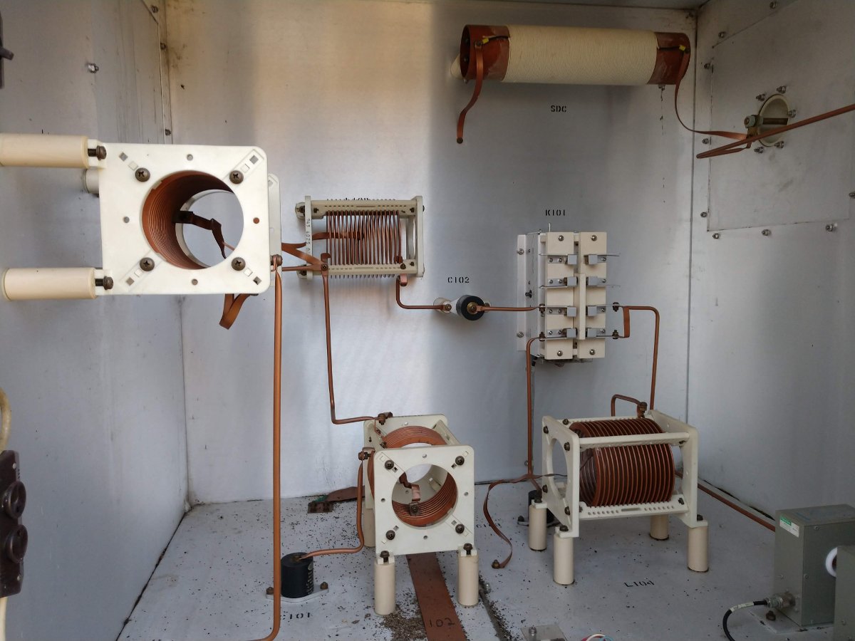
WBNR tower #1 Antenna Tuning Unit

The Phasor and ATUs are a late 80’s Harris product.  They are actually in remarkable shape, all things considered.  All of the RF contactors are Harris HS-4P motor-driven units.  They are rated at 30 Amps, RF-RMS.  I don’t think that they are supported by GatesAir.  I have a small stock of spare finger stock and contact bars.  I suppose, if I had to, I could make or adapt parts to repair.

Looking at the base currents and the base current ratios for both the day and night patterns (base current ratios are on the station license), the tower impedance has changed very little over thirty years. That is good news, especially with those 215-degree-tall nighttime towers.

The WBNR license application did contain an overall system diagram showing the Phasor and all the ATUs.  It did not contain any component ids or other information.  I scanned that in, created a vector graphics file, and expanded it to a 24 x 36 inch size.  I was able to fit all the component values and other information on the diagram.
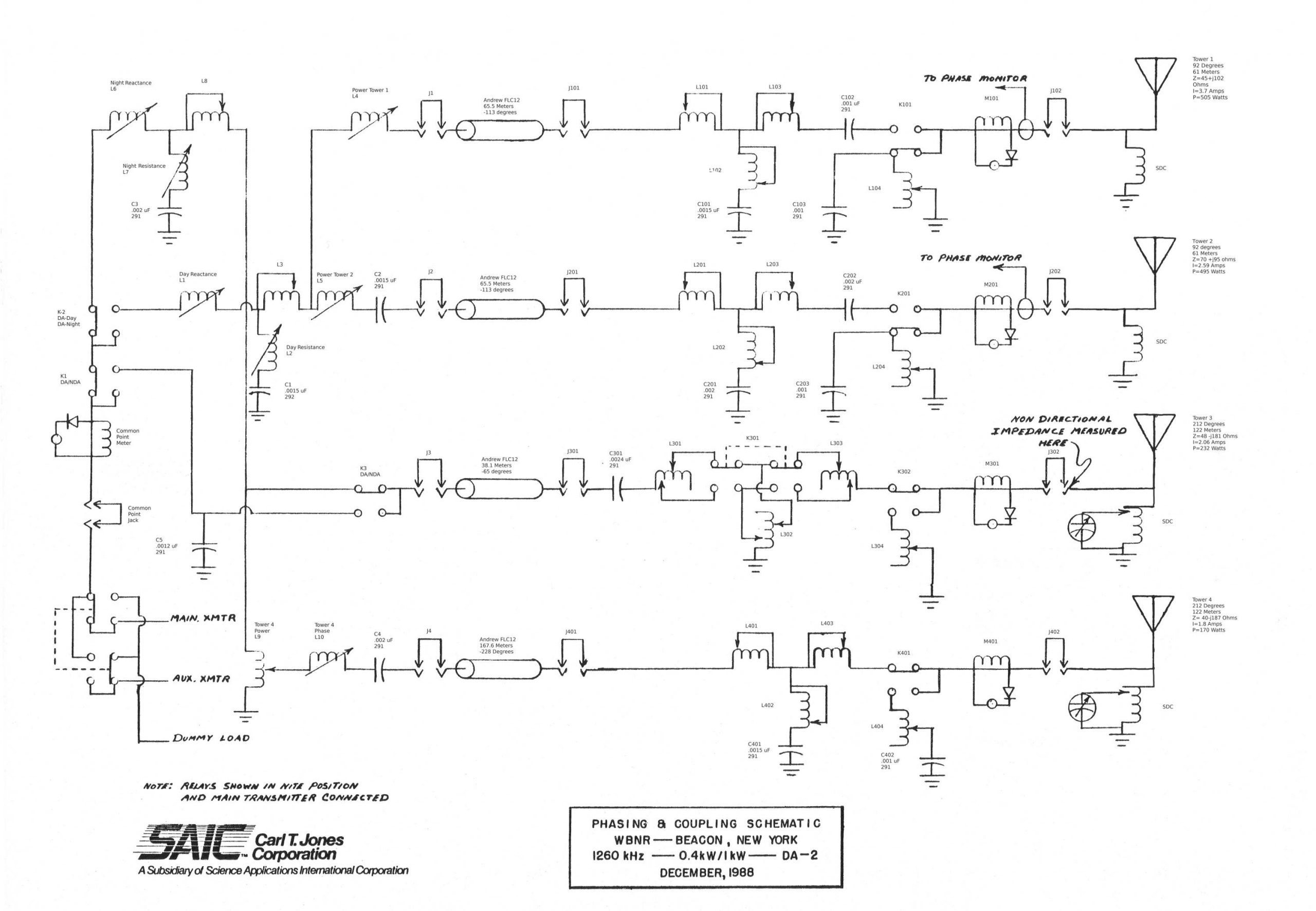
Schematic diagram WBNR day/night antenna systems

The other issue is the monitor point descriptions.  They include statements such as “Point is marked with yellow and white paint on a tree,” or “In the northeast corner of the Texaco research facility parking lot.”  Those references are long gone and I would prefer to use a set of GPS coordinates.  Using the topographical maps from the proofs, I found each monitor point and then recorded a set of GPS coordinates for each.  In the future, they will be much easier to find.  If anyone is still doing monitor points, I would recommend this method.

Yet another problem; the phasor control system was damaged by lightning. The overly complicated Harris Phasor control card was replaced with something more straightforward and reliable.   I designed a simple set of relays, one for daytime and one for nighttime, to change the antenna system over.  The transmitter interlock goes through the relay contacts, so the transmitter PDM is killed while the power changes.  Tally back from each of the towers is handled by a set of relays for each pattern, which is also interlocked with the transmitter.  All of this prevents the RF contactors from switching hot, something that has caused some damage in the past.

W243EM is 100 ERP watts, non-directional with a 1 bay Shively 6812-1R antenna installed at 381 feet (116 Meters) AGL on one of the nighttime towers.

The transmitter is a BW Broadcast TXT-600.  The power calculation is as follows:

ERP 100 Watts = 50 dBm
 
System gains and losses:
 
Transmission Line loss, 500 feet (152.4 Meters), RFS LCF78-50JA =  -1.75 dB
Isocoupler loss, Kintronic ISO-170-FM = -0.8 dB
Antenna gain, Shively 6812-1R = -3.39dB
 
Total system losses and gains: -5.94 dB
 
TPO: 55.94 dB or 393 Watts
 
With all that work completed, the license application was filed to cover the construction permit.  Once that was accepted by the FCC, program test authority was granted and the transmitter was turned on.  Hopefully, with the translator on the air, the perceptions regarding listeners will change and the station can bill more.
 
I really enjoy working on Medium Frequency antenna systems.  I don’t know why, but antenna systems in general are always fascinating to me.

A tale of five signals

I am currently finishing an interesting project involving putting up two translators on a diplexed AM tower which also holds a mobile phone/data tenant as well.  All-in-all, this seems to be a very efficient use of vertical real estate.

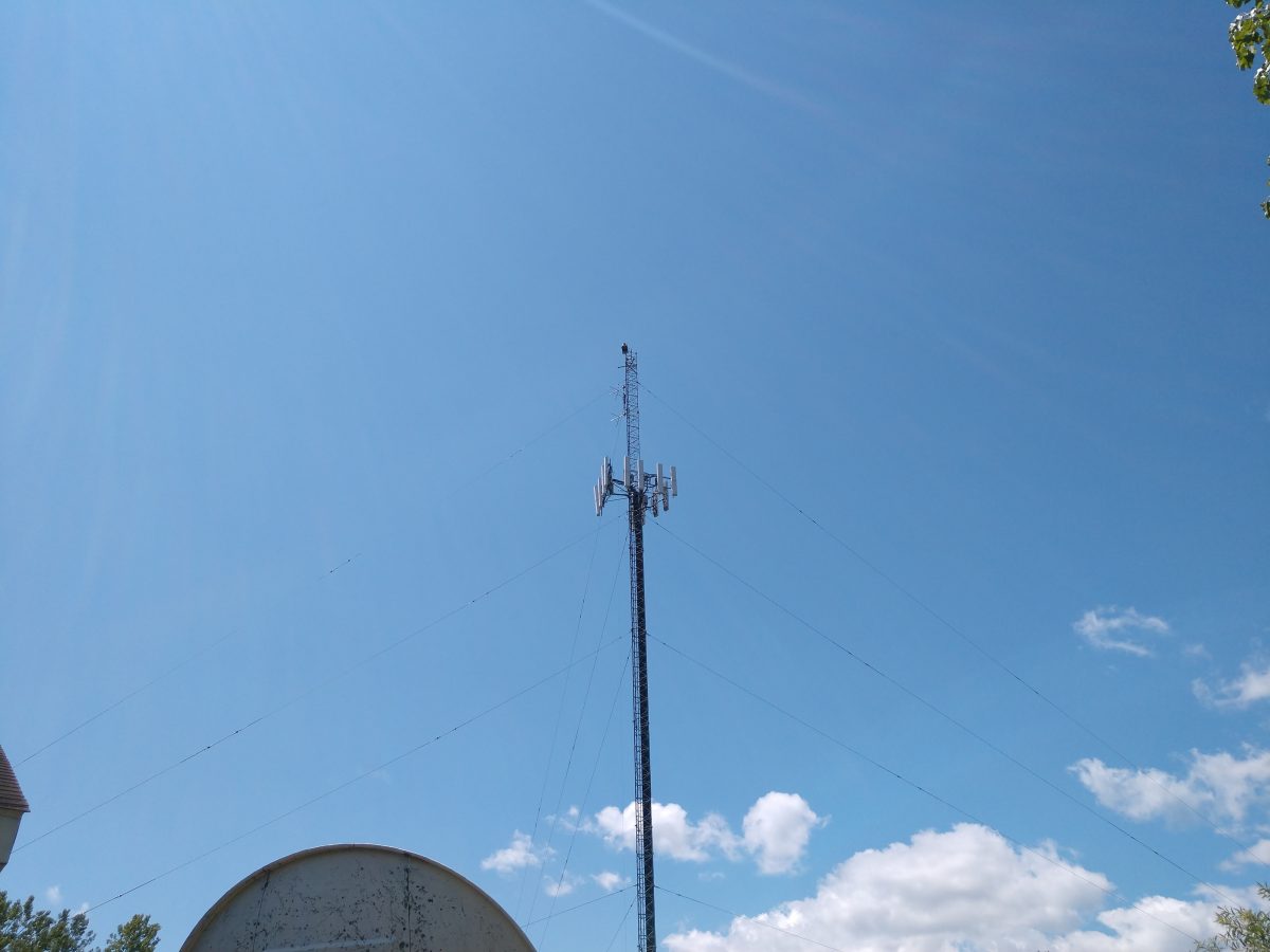
WMML WENU tower, Glens Falls, NY

The AM stations are WMML and WENU in Glens Falls, NY.  The AM stations are diplexed using a Phasetek diplexor/ATU.

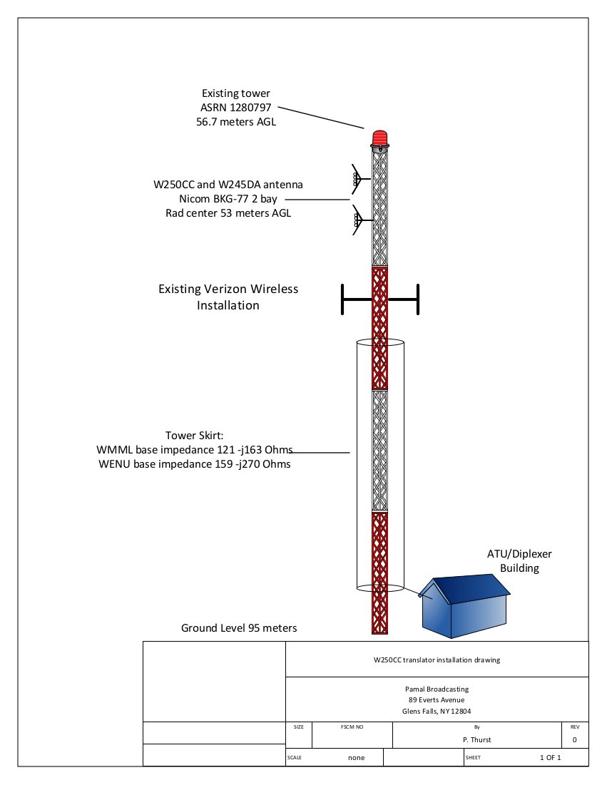
Diagram showing WENU/WMML tower with W250CC/W245DA antenna installed
Diplexor diagram, WENU/WMML Glens Falls, NY

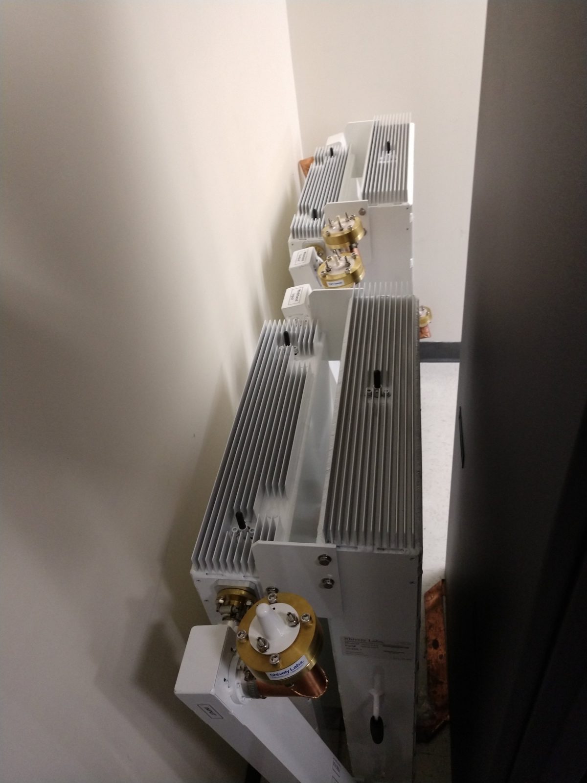
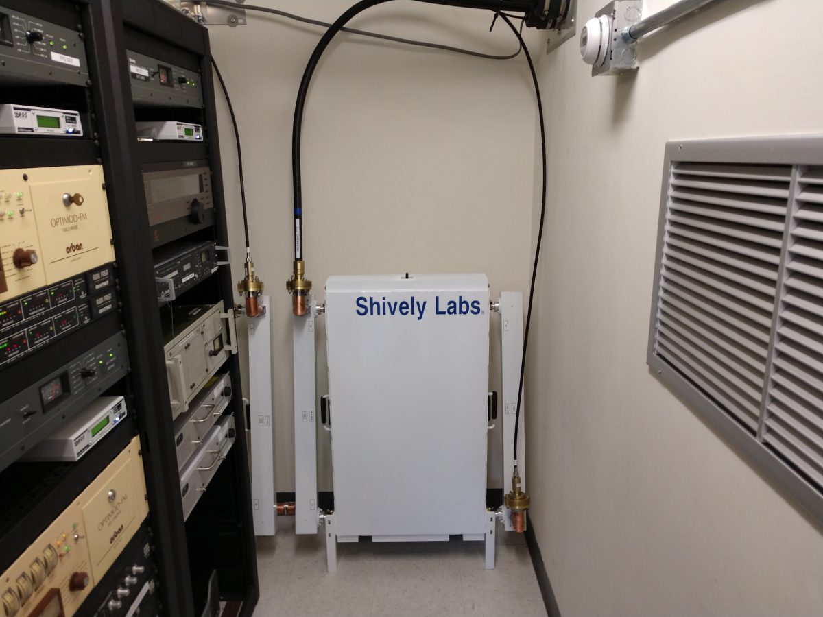
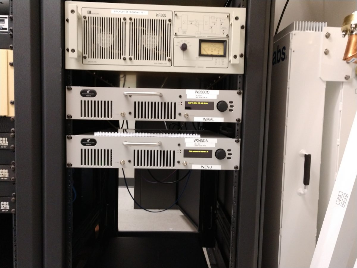
The translators are W250CC and W245DA which are using a NICOM BKG-77/2 two bay 3/4 wave spaced antenna mounted at 53 meters AGL.  The translators use a Shively 2640-04/2 filter/diplexor which is a broadband input port in addition to the translator input ports.  Since these translator signals are only 1 MHz apart, the higher-power Shively filter was installed because it has better rejection characteristics.  The broadband input port allows the NICOM antenna to be used as a backup for any of the three FM stations; WKBE 107.1, WNYQ 101.7, or WFFG 100.3.  Two transmitter sites for those stations are mountaintop locations which are very difficult to get to in the wintertime.  Having a backup site available takes some of the pressure off during storms or other emergencies.

Shively 2640 -04/2 filter for W250CC and W245DA

The NICOM FM antenna was mounted on the tower when W250CC went on the air in October 2016.  When it was installed, the base impedances for both AM stations were measured.  For some reason, WENU 1410 KHz seems to be more sensitive to any changes on the tower, thus the WENU ATU needed a slight touch-up.  When working on diplexed AM systems, it is also important to make sure that both trap filters, which are parallel resonant LC circuits, are tuned for maximum rejection of the other signal.  During this particular installation, nothing was added to the tower and no change in the base impedance for either station was noted.

Shively Filter, connected to transmitters and antenna

As a condition of the construction permit, measurement of spurious emissions of all stations sharing the common antenna needed to be completed to ensure compliance with FCC 73.317(b) and 73.317(d).  I made careful measurements of the potential intermod products between the two translator frequencies.  This measurement was completed with my TTI PSA6005 spectrum analyzer.

The primary concern here is mixing products between the two transmitters. Both transmitters are BW TXT-600 with low pass filters before the output connector. There are three frequencies of interest;

  1. (F1 – F2) + F1 or (97.9 MHz – 96.9 MHz ) + 97.9 MHz = 98.9 MHz
  2. F2 – (F1 – F2) or 96.9 MHz – (97.9 MHz – 96.9 MHz) = 95.9 MHz
  3. F2 + F1 or 97.9 MHz + 96.9 MHz = 194.8 MHz

That, plus harmonic measurements out to seven or eight harmonics of the fundamental frequency should be enough to demonstrate compliance with FCC out-of-band emissions standards. Being that this site has LTE carriers, it is very important to measure the harmonics in those bands. Mobile data systems often use receiver pre-amps, which can amplify harmonics from the FM band and make them look out of compliance. Having a base set of readings to fall back on is always the best course in case the “out of tolerance” condition gets reported to the FCC.

Measurements on these frequencies must meet the emissions standards outlined in FCC 73.317 (d), which states:

Any emission appearing on a frequency removed from the carrier by more than 600 kHz must be attenuated at least 43 + 10 Log10 (Power, in watts) dB below the level of the unmodulated carrier, or 80 dB, whichever is the lesser attenuation.

Harmonic frequencies to be measured:

Harmonics for 96.9 MHz fundamentalHarmonics for 97.9 MHz fundamentalComments
193.8195.8 
290.7293.7 
387.6391.6 
484.5489.5 
581.4587.4 
678.3*685.3*US LTE Band 71
775.2*783.2*US LTE Band 5
872.1*881.1*US LTE Band 5
969.0979.0 

*Frequencies that fall within the mobile data LTE bands. Traces were recorded and saved for these frequencies.

All of that information, once compiled is attached to the FCC form 350-FM, which, once filed grants Program Test Authority.

BW TXT-600 V2 translator transmitters
BW TXT-600 V2 translator transmitters under test and measurement

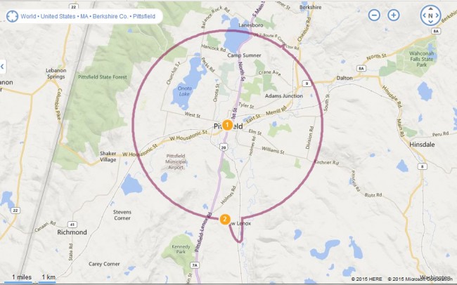
Pittsfield Massachusetts’ newest “Metro-Station” 103.3, W277CJ

We have been poking away at this one for the last year or so.  It seems that the previous owners of Berkshire Broadcasting had filed for a translator to rebroadcast WNMB, (100.1 WUPE-FM) North Adams in downtown Pittsfield, during the great translator rush of 2003.  When the CP showed up in the mail last March, the current owners were quite surprised.

After looking at the Construction Permit, we made some modifications;

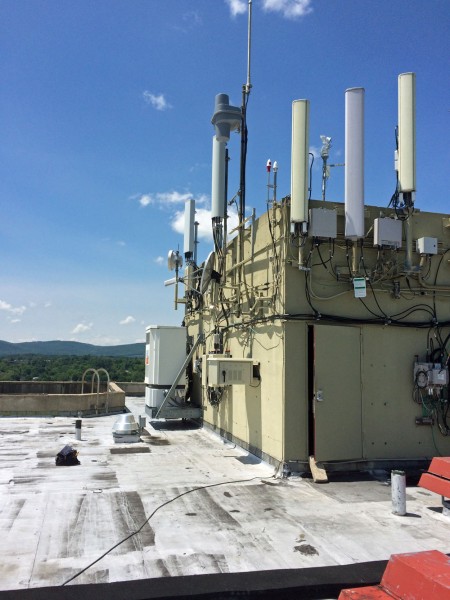
  • Moved the transmitter location from 100 North Street to 1 West Street (Crowne Plaza Hotel) which is the tallest building in Pittsfield.  Antenna AGL is 44 meters (145 feet).
  • Changed the rebroadcasting station from WUPE-FM, North Adams to WUPE-AM Pittsfield
  • Changed the antenna to non-directional
  • Changed the ERP from 48 watts to 100 watts

We were able to make those antenna and power changes because we changed the parent station to the local AM station, WUPE, 1,110 KHz.  The previous power/pattern was submitted to keep the translator signal within the 60 dBu contour of the FM station in North Adams.

This, I feel, is the best use for an AM to FM translator.  WUPE-AM is a class D station with no nighttime service.  Adding a nighttime service greatly increases the station’s value to the community.  While the 100 Watt translator does not cover nearly as much as the 5,000-watt AM station, the transmitter location is right in the center of Pittsfield, so coverage of the population center is excellent.

The view from the top of the Crowne Plaza is quite spectacular.  I am pretty sure I will have a lot of transmitter maintenance to do right about the middle of October.

W277CJ 60 dBu contour

The installation is fairly straightforward:

W277CJ installation, roof of Crowne Plaza, Pittsfield, MA
W277CJ transmitter in outdoor enclosure
W277CJ transmitter in an outdoor enclosure

The outdoor enclosure is a DDB POD-16DXC which is rather nice, it comes with rack rails and a thermostatically controlled fan.

W277CJ Shively 6812B antenna

The antenna is a Shively 6812B with RADOMES. The transmitter is a BW Broadcast TX600v2.  I really like these transmitters, they are well-designed and rugged.  We have yet to have a single failure of one of these units in the field.

The station ERP is 100 watts, so a small bit of calculating is required to arrive at the proper station TPO.  I find it easier to make all these calculations in the decibels per milliwatt (dBm) unit domain, then convert them back to watts.  Thus, the ERP is 100 watts or 50 dBm.  The antenna has a gain of -3.4 dBm.  We used 25 feet of LMR-400, which at 103.3 MHz, has a loss of -0.26 dBm.  The total losses are -3.66 dBm, making the necessary TPO 53.66 dBm, 232.27 watts, or rounding down to 232 watts.

FCC seeks further comment on Low Power FM (LPFM)

While I was away, the FCC released a Further Notice of Proposed Rule Making (11-105) regarding LPFM and translators.  There are several issues with a backlog of translator applications and the possible LPFM window that looms out in the future somewhere.  The current FCC translator rules bear little or no resemblance to the reality of FM translator use today.

The basic translator rules are found in FCC 74.1206 through 74.1290 with the programming and permissible service outlined in FCC 74.1231:

Sec. 74.1231 Purpose and permissible service.

(a) FM translators provide a means whereby the signals of AM or FM broadcast stations may be retransmitted to areas in which direct reception of such AM or FM broadcast stations is unsatisfactory due to distance or intervening terrain barriers, and a means for AM Class D stations to continue operating at night.
(b) An FM translator may be used for the purpose of retransmitting the signals of a primary AM or FM radio broadcast station or another translator station the signal of which is received directly through space, converted, and suitably amplified, and originating programming to the extent authorized in paragraphs (f), (g), and (h) of this section. However, an FM translator providing fill-in service may use any terrestrial facilities to receive the signal that is being rebroadcast. An FM booster station or a noncommercial educational FM translator station that is operating on a reserved channel (Channels 201-220) and is owned and operated by the licensee of the primary noncommercial educational station it rebroadcasts may use alternative signal delivery means, including, but not limited to, satellite and terrestrial microwave facilities. Provided, however, that an applicant for a noncommercial educational translator operating on a reserved channel (Channel 201-220) and owned and operated by the licensee of the primary noncommercial educational AM or FM station it rebroadcasts complies with either paragraph (b)(1) or (b)(2) of this section:
(1) The applicant demonstrates that:
(i) The transmitter site of the proposed FM translator station is within 80 kilometers of the predicted 1 mV/m contour of the primary station to be rebroadcast; or,
(ii) The transmitter site of the proposed FM translator station is more than 160 kilometers from the transmitter site of any authorized full service noncommercial educational FM station; or,
(iii) The application is mutually exclusive with an application containing the showing as required by paragraph 74.1231(b)(2) (i) or (ii) of this section; or,
(iv) The application is filed after October 1, 1992.
(2) If the transmitter site of the proposed FM translator station is more than 80 kilometers from the predicted 1 mV/m contour of the primary station to be rebroadcast or is within 160 kilometers of the transmitter site of any authorized full service noncommercial educational FM station, the applicant must show that:
(i) An alternative frequency can be used at the same site as the proposed FM translator’s transmitter location and can provide signal coverage to the same area encompassed by the applicant’s proposed 1 mV/m contour; or,
(ii) An alternative frequency can be used at a different site and can provide signal coverage to the same area encompassed by the applicant’s proposed 1 mV/m contour.
(c) The transmissions of each FM translator or booster station shall be intended only for direct reception by the general public. An FM translator or booster shall not be operated solely for the purpose of relaying signals to one or more fixed received points for retransmission, distribution, or further relaying in order to establish a point-to-point FM radio relay system.
(d) The technical characteristics of the retransmitted signals shall not be deliberately altered so as to hinder reception on conventional FM broadcast receivers.
(e) An FM translator shall not deliberately retransmit the signals of any station other than the station it is authorized to retransmit. Precautions shall be taken to avoid unintentional retransmission of such other signals.
(f) A locally generated radio frequency signal similar to that of an FM broadcast station and modulated with aural information may be connected to the input terminals of an FM translator for the purpose of transmitting voice announcements. The radio frequency signals shall be on the same channel as the normally used off-the-air signal being rebroadcast. Connection of the locally generated signals shall be made by any automatic means when transmitting originations concerning
financial support. The connections for emergency transmissions may be made manually. The apparatus used to generate the local signal that is used to modulate the FM translator must be capable of producing an aural signal which will provide acceptable reception on FM receivers designed for the transmission standards employed by FM broadcast stations.
(g) The aural material transmitted as permitted in paragraph (f) of this section shall be limited to emergency warnings of imminent danger and to seeking or acknowledging financial support deemed necessary to the continued operation of the translator. Originations concerning financial support are limited to a total of 30 seconds an hour. Within this limitation the length of any particular announcement will be left to the discretion of the translator station licensee. Solicitations of contributions shall be limited to the defrayal of the costs of installation, operation and maintenance of the translator or acknowledgements of financial support for those purposes. Such acknowledgements may include identification of the contributors, the size or nature of the contributions and advertising messages of contributors. Emergency transmissions shall be no longer or more frequent than necessary to protect life and property.
(h) An FM translator station that rebroadcasts a Class D AM radio broadcast station as its primary station may originate programming during the hours the primary station is not operating, subject to the provisions of Sec. 74.1263(b) of this part.
(i) FM broadcast booster stations provide a means whereby the licensee of an FM broadcast station may provide service to areas in any region within the primary station’s predicted, authorized service contours. An FM broadcast booster station is authorized to retransmit only the signals of its primary station which have been received directly through space and suitably amplified, or received by alternative signal delivery means including, but not limited to, satellite and terrestrial microwave facilities. The FM booster station shall not retransmit the signals of any other station nor make independent transmissions, except that locally generated signals may be used to excite the booster apparatus for the purpose of conducting tests and measurements essential to the proper installation and maintenance of the apparatus.

With a  possible exception for use by Class D AM stations, the translator service has gone far away from what it was intended to be and even, in some cases, contradicts the current rules.  DIY Media goes more into this in Unholy Alliance.

Consolidators are using translators to get around market ownership caps by using them to re-broadcast HD-2 and HD-3 channels, which would otherwise go unheard.  Others are using translators to establish large networks of over-the-air relays to greatly extend their coverage far beyond any natural signal contour.  Religious and public radio stations rely extensively on translators to establish radio signals that are several times the size of the original station.  In one case, a translator in Harrisburg, PA is broadcasting a satellite feed of the True Oldies Channel that does not appear on any AM, FM or HD sub-channel in the market.  The 80/160 KM distances noted above in section B(1)(i) and (ii) seem to be largely ignored.

What the FCC wants to know is this: There are thousands of pending translator applications; what is to be done about them in light of the new LPFM legislation Congress passed last year?  Should they be dismissed, approved, or some market-based combination of the two?  Keep in mind, the new LPFM stations are on an equal regulatory footing with translators, unlike full-power FM or the previous LPFM licenses granted in 2003.

Whatever the outcome, it would appear that this will be the final chance to get an LPFM license when the filing window opens.   After this, there will likely not be a scrap of spectrum left to dole out.  The deadline for filing comments with the FCC is August 29th.