This is a set of burned contactor fingers on a Harris HS-4P 30 amp RF contactor:
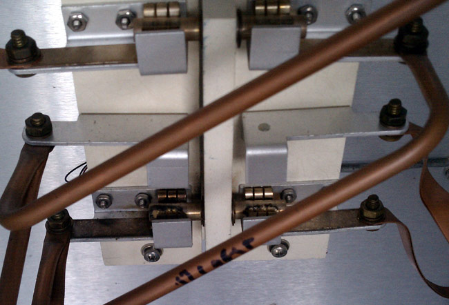
The back story is this:
The contactor in question is at the base of Tower #3 of the WBNR (1260 KHz, Beacon, NY) antenna array. This is the tallest of all the towers, at 405 feet. As such, it gets struck by lightning often. There was at least one occasion where one of the inductors in the ATU got “sucked in” due to the huge magnetic field of a high current strike. It is not at all surprising to me to find other component issues in this ATU. Because of the burned contacts, I’d suspect that the station was switching modes under power, but I didn’t see that happening today.
The problem manifested itself in very high SWR after changing over from day pattern to night pattern. This did not occur every time, in fact, it only occurred once in a great while at first. Then, over the last couple of months, it began occurring more and more often. Since the snow drifts are now down to a manageable six to eight inches, it was a good day to go out and do some exploring.
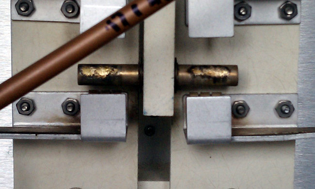
First of all, I put the station into nighttime mode just to confirm that there is still an issue. The transmitter, a Broadcast Electronics AM1A showed very high SWR and carrier fold back. Left it in night pattern, but turned it off and took a walk, not a drive, to Tower #4 which is all the way at the bottom of a hill, near the old City of Beacon landfill. I figured that I would check that one first, then look at Tower #3 on the way back. When I got to Tower #3, I found the issue right away.
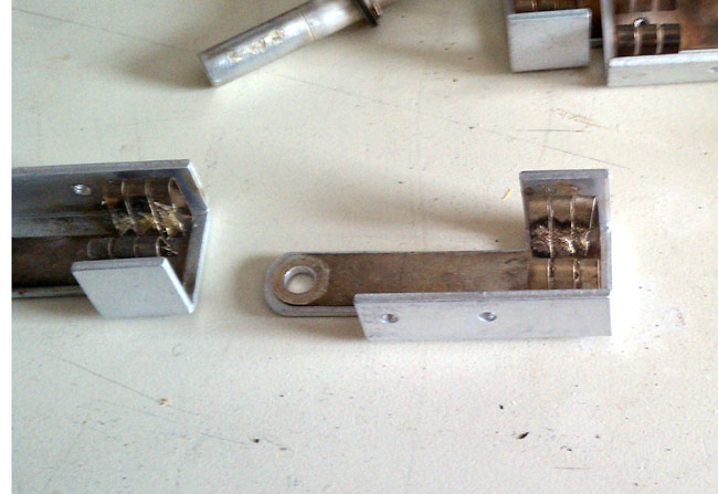
Fortunately, I was able to salvage a set of contact and contactor bar from another relay in the same ATU that was not using them.
The night pattern is only 400 watts, but these are tall towers, 225 degrees, therefore current and voltage are high at the base. In fact, the slightest change at the base of the nighttime towers will greatly upset things.
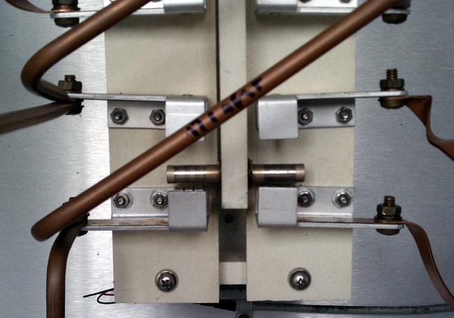
This is the repaired contactor. I will say, the EF Johnson RF contactors are easier to work on. Those are the ones with the big rocker bar across the top and two solenoids on either side. All of the wiring, status switches and contacts are exposed and easy to get to. This one, not so much. This is the BE AM1A transmitter
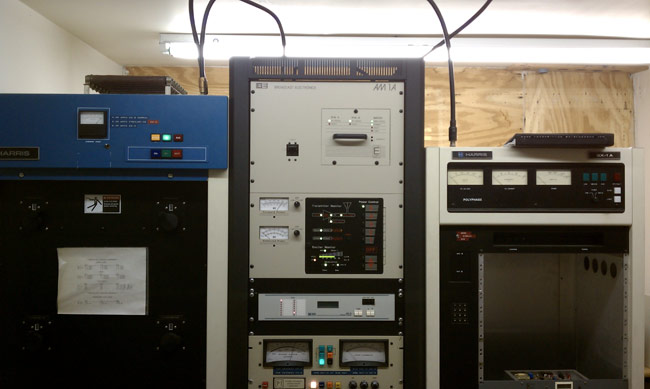
It is not a bad unit, compact, sounds good, is reliable, etc. In order to work on the power supply or anything in that top cabinet, the whole thing needs to be removed from the rack and taken down. I suppose that is my only gripe about the thing.

The Lessner brothers would be proud!
I think you need some series inductance in series with the feed to the tall tower. A 3 turn coil of 1/2 soft-drawn copper tubing (flattened at each end for fastening) approximately 12 inches in diameter with 2 inch spacing between turns should be an effective lightning choke. The additional inductive reactance presented by this choke is almost negligible at 1260 kHz. and could easily be tuned out with a series capacitor if need be. The grounding integrity at this tower should also be checked. As for BE, their specs are good, but I am no big fan of their construction as it relates to serviceability. I think their engineers are computer types with no practical experience with a screwdriver or soldering iron. They like “switch-mode” power supplies which I have absolutely no affection for. Poor longevity, failure without warning, and basically a throw-away consumer mentality does not belong in broadcast transmitter design. Building something as cheap as possible isn’t always a winner, and I would gladly pay more for quality and reliability. It seems that todays broadcasters are expected to buy a new transmitter every 5 years, kind of like computers. When an EMP comes, these solid-state wonders will all fail, while my tube-type transmitters are very likely to survive.
The feed between the ATU and tower is set up just as you say, 1/2 inch copper tubing with 3 turns about 10 inches in diameter. The tower grounding is intact. In fact, this tower gets hit often, several times a summer, with no back results. It is that one in one hundred super strike that causes problems. The issue is that it is the tallest thing in the city of beacon, so it is the lightning rod.
Regarding the transmitter, that particular unit has been pretty reliable. We had one issue with the directional coupler which was replaced under warranty. Regarding tube transmitters, you are correct. If I where a radio station owner, I’d keep a tube type transmitter around as a backup. Some of those old RCA, Gates Radio, GE, etc transmitters would be hard to kill.
Is there a “horn gap” in addition across the base? If not, this gap could be installed just above the feed point and that would give you more protection. Another thing to consider are lighting conduits. If they are on insulated hangers, a large induced voltage can occur between the conduit and ground with a direct lightning strike. I would look over the tower lighting chokes if used and see that they are connected with a good ground connection. Also, if the lighting conduit is connected to the tower, I would inspect the point directly where the conduit leaves the tower. This can be another induced high-voltage point during a lightning strike if the bonding is faulty or broken. Austin-Ring transformers are better lightning isolators, but they are expensive and probably out of the question these days.
I see you moved the phasor 🙂
Nope, Phasor is in the same place, the transmitters have moved around a bit though…