This is part I of II.
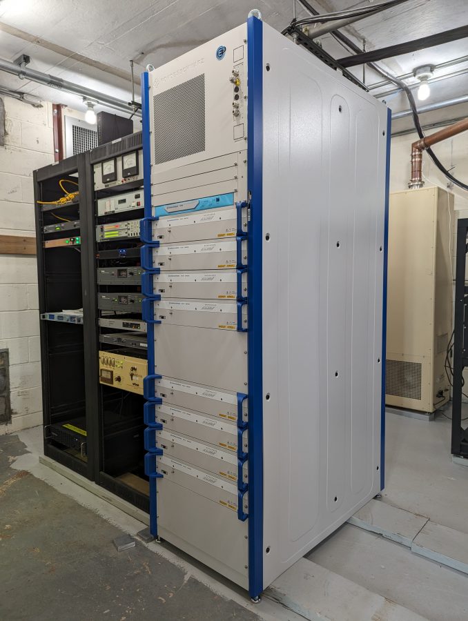
We are in the process of installing an R&S 40 KW liquid-cooled FM transmitter. My first comment; these are well-built units. A quick look at the machining of the parts indicates attention to detail is a key design feature.
As the price of electricity continues to rise, liquid-cooled transmitters for this power level make a lot of sense.
This installation is for Pamal Broadcasting’s WHUD, Peekskill, New York. The site has undergone major upgrades in the last few years. The original 1958 World Tower Utility 80 was replaced a year ago with this Valmont 60X394. Two cell carriers, two translators, and several E911 services are now colocated on the tower.

The transmitter building is also the original cinder block structure from 1958. When it signed on, the station had a Gates FM5B 5 KW transmitter, an RCA BFA-7, 7-bay horizontally polarized antenna with an ERP of 20 KW. In 1970, that antenna was changed out to a 6-bay circularly polarized ERI with a Harris FM20H transmitter, increasing the ERP to 50 KW. As of now, the station has a 4-bay ERI SHP-4-A-C main antenna and the TPO is 28 KW for the same 50 KW ERP. As the station’s power increased, the building became a little bit smaller than optimal. We needed to rearrange some equipment to gain space for the pump station and step-up transformer.
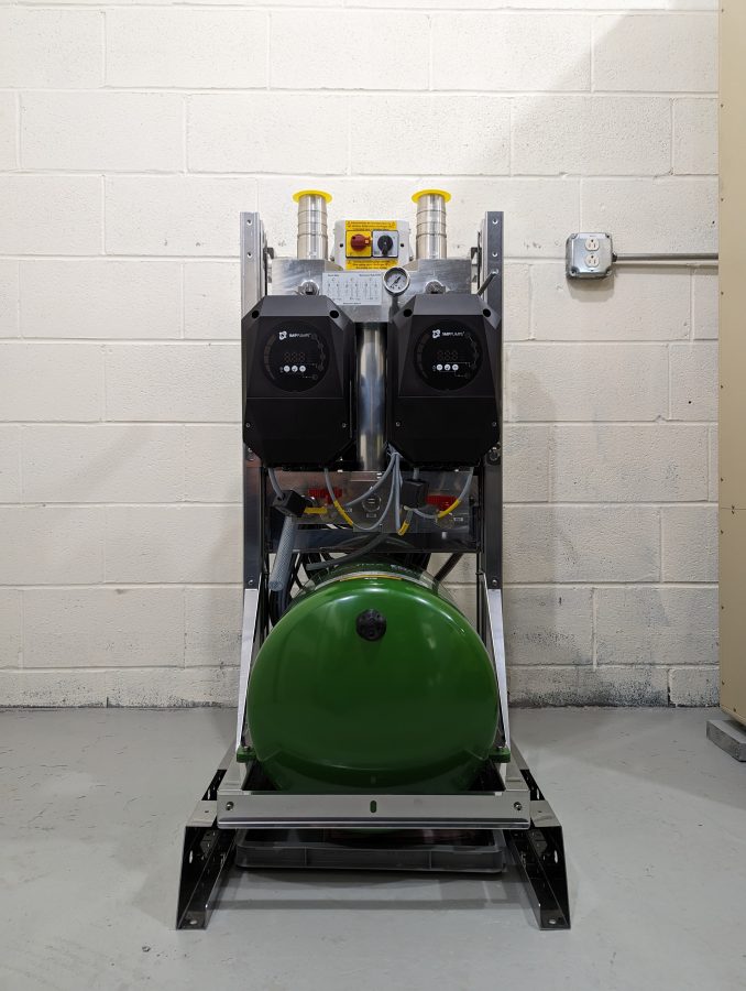
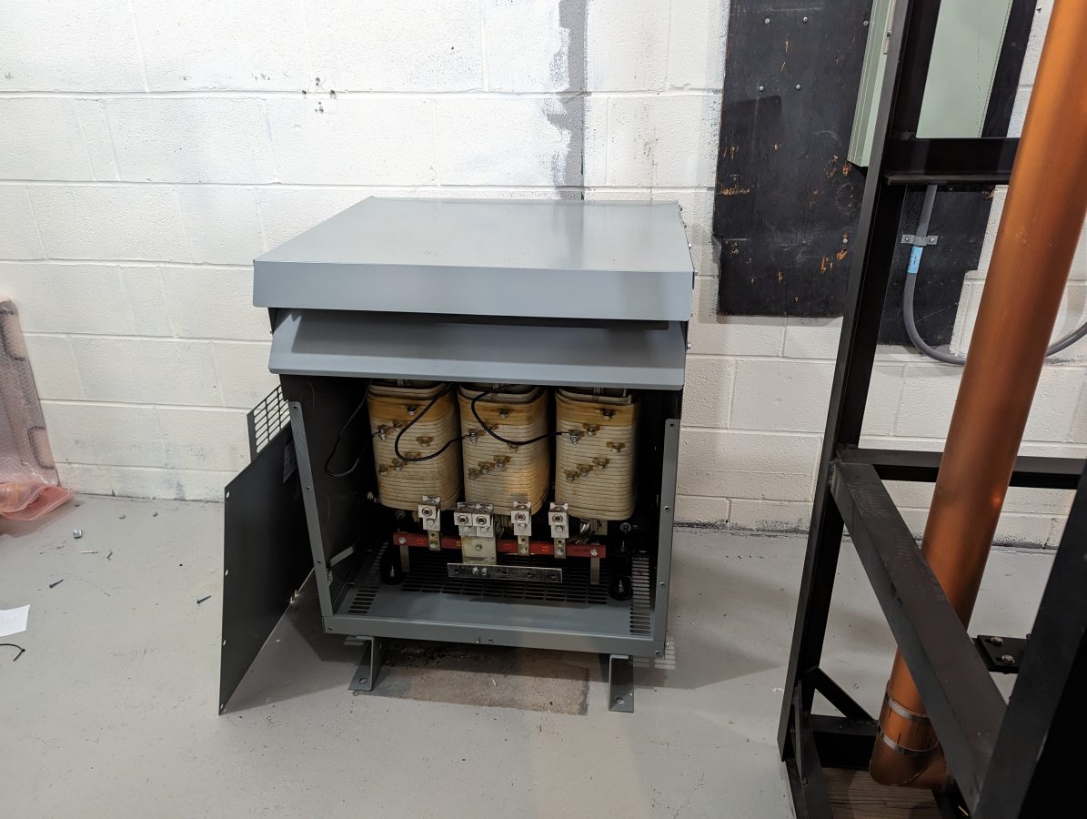
Rhode Schwarz recommended installing a step-up transformer for the incoming AC mains. The power supplies run most efficiently with 400 volts AC.
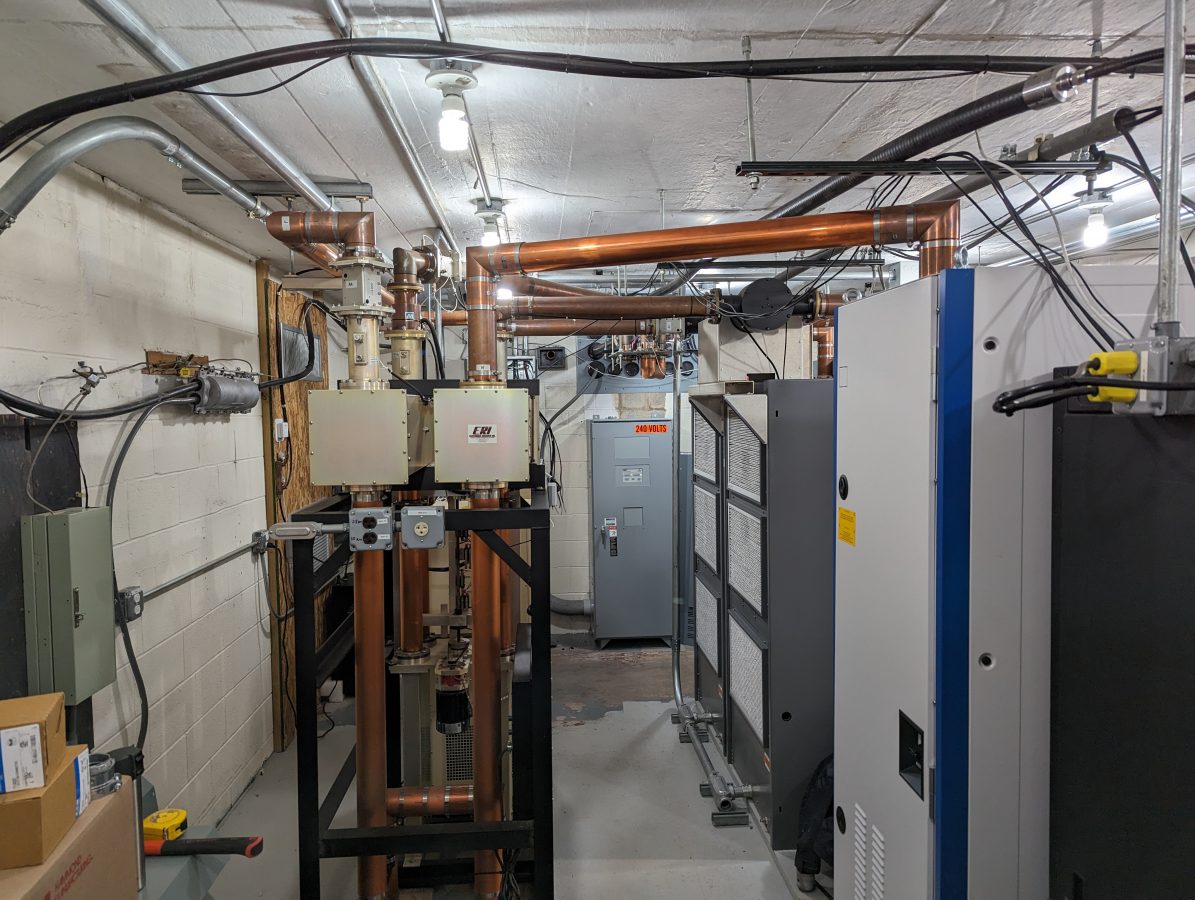
We decided to reuse the ERI switchless combiner left over from the Nautel V-40 installation. There are two Nautel V-10 transmitters with a hybrid combiner that are to be used as a backup. We won’t be running this as a combined transmitter operation, it is a way to save money rather than install a separate 3-inch coax switch. I will build a simple control panel to move the combiner position either all the way up (THR9) or all the way down (V-10s).
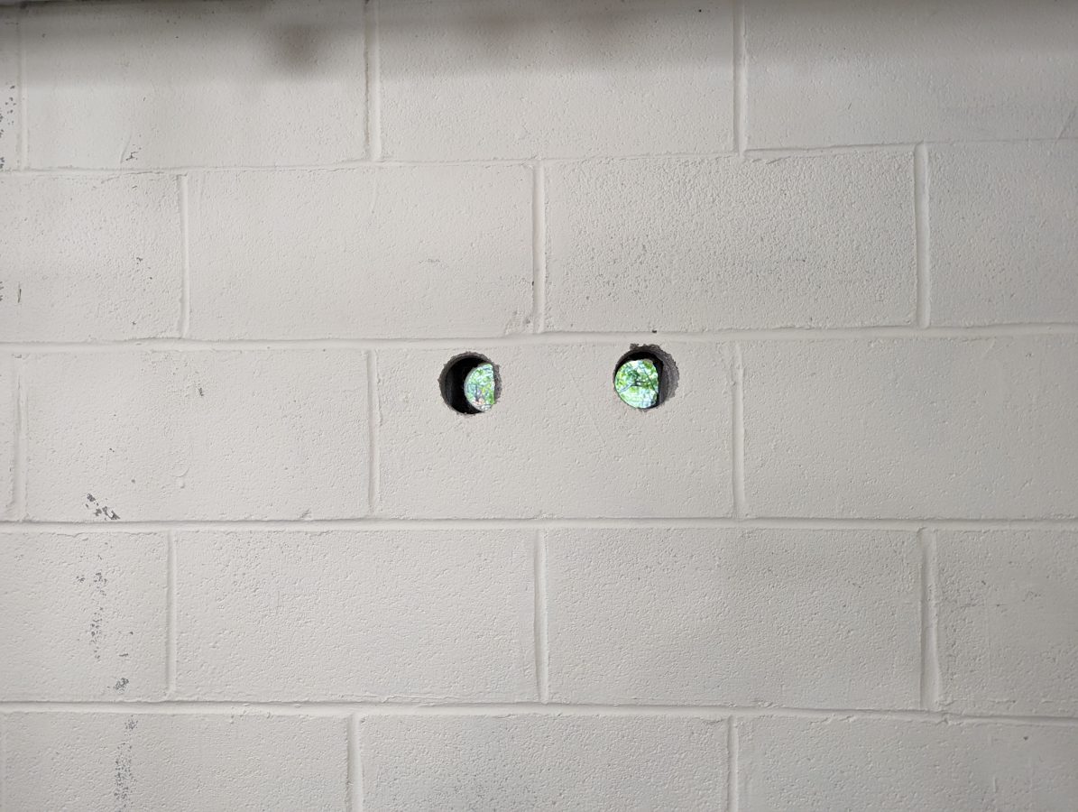
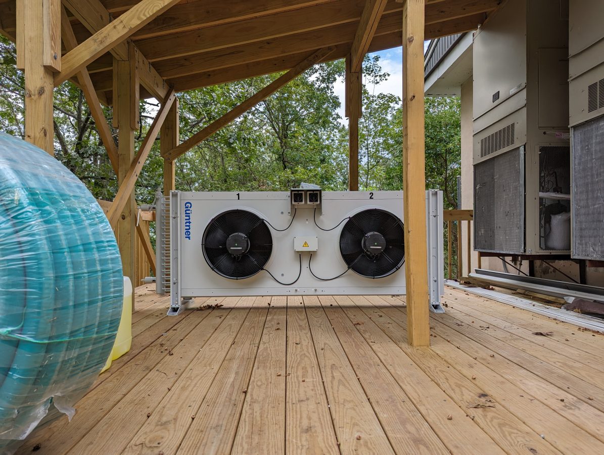
Working on the liquid cooling system. I used a core drill to make the supply and return lines to the outdoor heat exchanger. I made sure that I had the shop vac (with a HEPA filter) running while drilling so that all of the concrete dust was captured. That stuff can get everywhere and has a bad tendency to destroy motor bearings. Whatever plant made these blocks in 1958, they used some hard material. It took a while for my masonry drill to get through them.

Installation looks nice.
I didn’t know Valmont made towers. When I was a kid, they were best known for center-pivot irrigation, and I know they diversified into making traffic-signal standards and monopoles decades ago.
Gregg, thanks! I’ll post some more in-progress pictures as things move along. Valmont purchased Pirod towers sometime around 2006 I believe, before that they did mainly monopoles. The tower itself is pretty stout.
Looking good! I seriously looked at and even got quotes for Rhode Schwarz transmitters to replace a couple aging BEs but more money up front than we could spend so ended up with Nautel and I’m not sorry about that…. We have a station at a site that installed a Rhode Schwarz feeding four combined stations out of two cabinets. I helped the local engineer put that together and I’m impressed with these rigs.
Keep us posted on your progress!
Is that a single stage heat exchanger or two stage heat exchanger system? How are your plumbing skills? You’ll probably be working on the heat exchanger more than the actual transmitter!
Nice looking install! Might be fair to guess that those bricks were made to be blast resistant.
Appreciate seeing another nice install. I must be old or something, when I see “Rohde und Schwarz”, I think very high end test gear, but I’ll bet they make top notch broadcast transmitters too. What is old is new again. The earliest broadcast transmitters of any power were liquid cooled (like WLW’s half megawatt monster), now it looks like that’s the way things are heading again.
Had some core drilling done through a concrete block wall for 3-1/8″ coax. When they got through the one side there was vermiculite pouring out of the wall. Mad scramble to clean up/remediate. Quite a few cans of foam kept it at bay.
May the Schwarz be with you, Paul.
Thank you, Dan! That is one of my favorite Mel Brooks movies.
I assume the energy savings here has to do with the direct heat exchange unit vs. cooling the air in the room, correct? Any (really general) ballpark on how much energy savings that brings? Or some numbers like “the old way costs $X per 1,000 BTU of heat taken out of the building, the new way costs $Y?”?
Also curious about the step-up transformer, how efficient is that?
All good questions; the energy savings comes from avoiding a refrigeration cycle, which is more energy intensive than the pumps and fans to move the liquid coolant outdoors and dissipate. As far as energy savings, we will be able to make a direct comparison once this has been operating for a few months and we can look at the electric usage. I will post an update when that information is available. This site has a demand meter, so it may be a dollars-to-donuts comparison as far as expense goes, however, the difference in electrical usage (in kWh) should be accurate.
The manufacturer states that the transformer is 98.94% efficient, so basically 1% loss. Given the TPO and transmitter efficiency, I expect the transformer to dissipate about 400 watts continuously, or 1,365 BTU.
I’m curious, Paul – In a cold climate, could the waste heat be used to warm the slab and heat the studio (provided they are at the transmitter site?)
Geoff, theoretically, yes as long as the slab could dissipate enough heat to keep the HTF at a constant temperature. One of the benefits of liquid cooling is that the devices do not heat cycle. One of the things that transmitter manufacturers are finding is the device output can drop over time. LDMOS devices are very dense with tiny semiconductor junctions. These junctions can fail (go open) and it appears that heat cycling may be one of the culprits. Keeping the HTF at a constant temperature by varying the pump speed and fan speed eliminates heat cycling.
Congratulations on a really modern installation. Here in Brazil, electricity costs are high. I am currently planning a new installation for 2 FM stations operating solid state transmitters working in the same location. The nominal powers will be 6.5 kw (103.1) and 4.9 kw (86.5). Still worried about how to build a place to keep the temperature controlled and also to remove the heat generated by the transmitters. It is a challenge for us as we never operate two transmitters simultaneously. I’m happy if you can get some drawing/scheme to start the study. Thank you again, every day learning more from you.