I found this in the great clean out of 2010, Bridgeport, Connecticut. Once upon a time, I had a slightly newer version of this, I think from 1972 or so. This version is from 1964 and gives a complete rundown of most small tubes that were manufactured back then.
There is something about a well-designed, well-maintained piece of tube gear. I remember an old Collins tube console that was in a production room at a small AM station. The console went dead (the paper clip shorted the B+) and I fixed it.
I recall listening to the test recording of my own voice from a reel-to-reel machine when I fixed the console. It sounded better than I’d ever heard it, not that I have a great radio voice, by any means.
A tube is a voltage amplifier versus a transistor, which is a current amplifier. A tube does not have the same fidelity as a transistor, as the voltage reaches its peak, it gets a little fuzzy, adding some distortion and harmonics. Tube gear adds warmth, what a musician might call Timbre. The combination of fundamental frequency and varying amplitudes of harmonic frequencies allow a listener to tell the difference between a piano and a guitar playing the same note.
This is what the current crop of tube mic preamps and other tube products tries to reproduce. Several companies have come out with an amplifier design that has mostly transistors and one tube, usually a 12AX7. Unfortunately, at least in my opinion, they fall a little short. If you want to have the “tube sound,” it needs to be all hollow state.
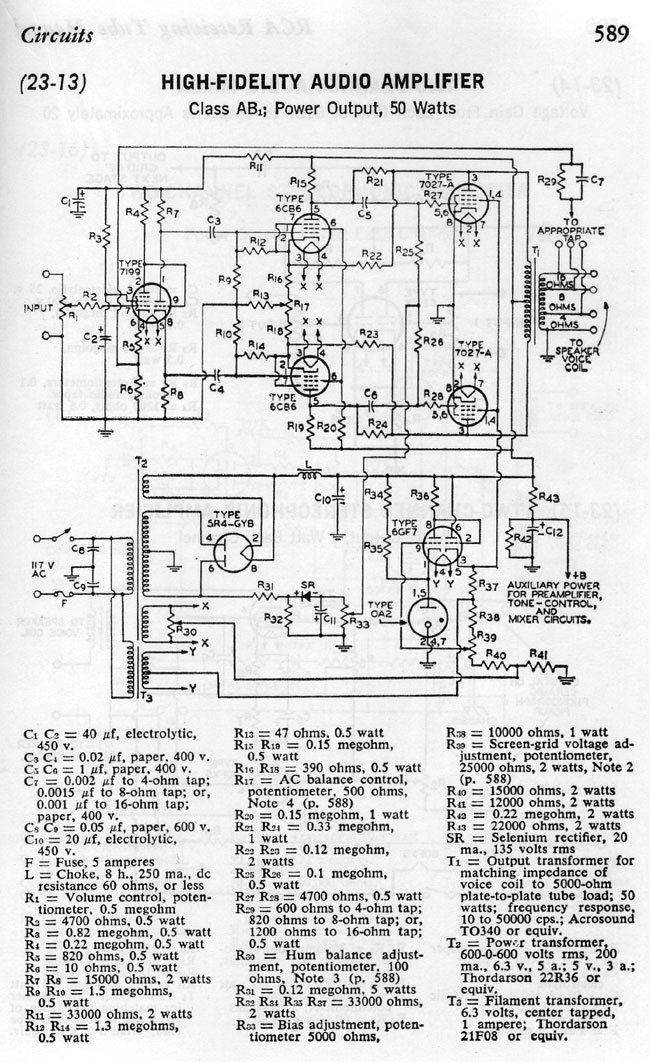
What is intriguing to me are the schematic diagrams in the back of the book. There is one for an audio amplifier:
RCA receiving tube manual audio amp schematic diagram, C 1964
This is a single-channel unit, for stereo, it would need to be duplicated. Also, I would lose the tube rectifier in favor of a solid-state full wave bridge, which would simplify T2 somewhat. The OA2 could also be changed to a diode. Looks like unbalanced audio, which could be modified with an input transformer.
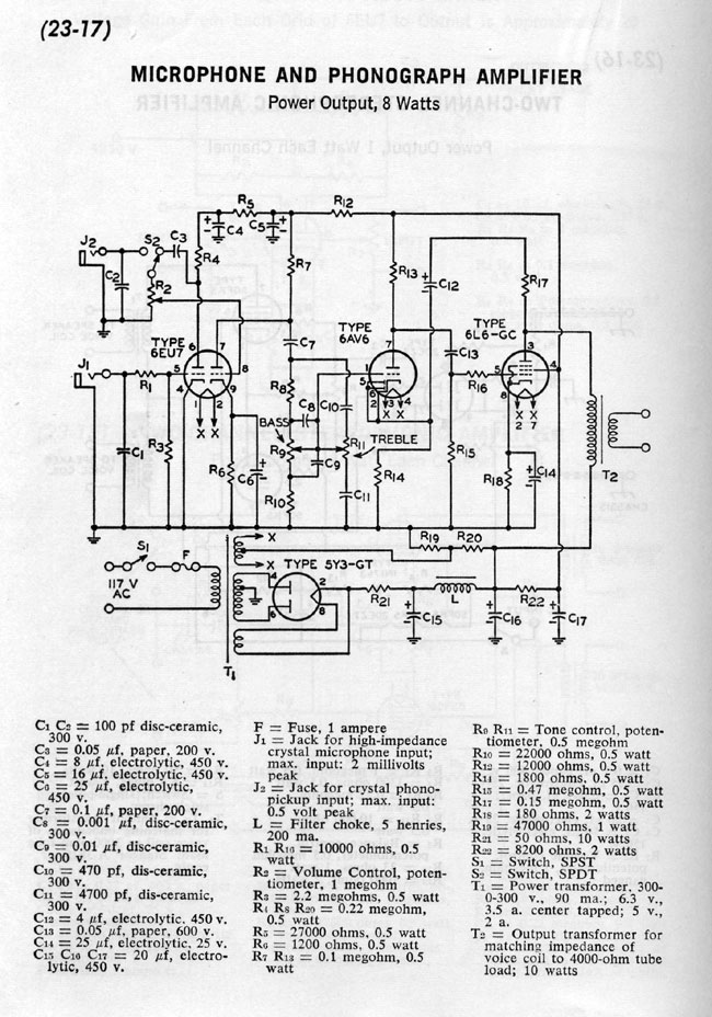
Another interesting diagram is this one, which can be used as a mic preamp:
Microphone Preamp schematic diagram RCA receiving tube manual C 196
That looks like a pretty solid design, a few tweaks here or there to add some gain reduction and some type of output level adjustment and I would be a really cool piece of gear. Again, the tube rectifier could be replaced with something solid state. The output transformer would likely have to be changed to something like 600 ohms.
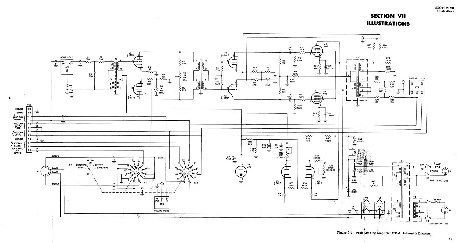
Couple that to something like this, the Collins 26U compressor/limiter, and one would have a great sounding microphone processor:
Collins 26U compressor limiter
Looks pretty cool. R10 is used to balance the two plate currents. I would be interested in the transformer values, input/output impedances, voltages, etc. The 6386 tube is very hard to find these days, a good substitute would be a 5670 which is still made by several manufacturers.
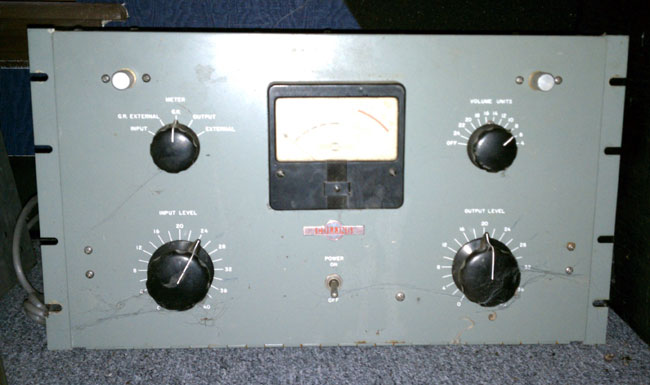
Update: This is a picture of a Collins 26-U sitting on my boss’s floor.
It they don’t care all that much about traditional phone service anymore. Through attrition, they have reduced their tech workforce to about half what it was 15 years ago. All of the infrastructure; overhead cables, buried cables, office frames, switching equipment, is getting old. Some of the cabling around here, both buried and overhead, is the original stuff, installed 100 years ago. Because it is expensive to replace, they don’t want to change it out, opting to simply limp along, swapping out pairs when a line or circuit goes dead.
I will be surprised if the traditional wired telephone network still exists in ten years. Think about it, ten years ago were just heaving a collective sigh of relief that Y2K turned out to be nothing, remember that?
For the local phone giant, offering 3 in one (telephone service, internet service, and cable TV) is more appealing than servicing their existing accounts, including HICAP (high capacity) data circuits like T-1, BRI&PRI ISDN, etc. Much less so for a POTS line, which, good luck if you really need it fixed right away, we’ll be over when we get to it, just keep your paints on mister.
I’ve written about this before. A particular station for my former employer uses a T-1 circuit to relay the program from the studio to the transmitter site. This is fairly common in larger metropolitan areas where 950 Mhz STL frequencies are not available, nor is a line of sight between the studio and transmitter site obtainable.
Back in 2002, when the company was in the process of acquiring said station, I recommended a 950 Mhz STL. There was an existing STL license, fully coordinated, that came with the main station license. Only the equipment was needed. No, I was told by the CFO, we will do a T-1, thank you very much. I argued my point, saying that putting our radio station exclusively in the hands of the phone company was a bad idea. We would have problems with outages and service. No, said the CFO, this is New York, all the radio stations do that. Not exactly, New York is about 15 miles SOUTH of here, this is Westchester, the cables are old, and a lot of them are overhead, which exposes them to lightning, vehicle damage, water, etc. There will be service issues if we rely solely on a T-1.
No, he said, “We are using a T-1 and that is final.” I hate to say I told you so, but… Let us examine the history between then and now:
Date of outage
Date of restoration
Total days
April 5, 2004
April 9, 2004
4
September 8, 2006
September 10, 2006
2
May 2, 2007
May 5, 2007
3
August 27, 2009
September 4, 2009
10
September 5, 2010
September 15, 2010
10
Fortunately, I wrote all this down in the transmitter site log. I was able to check it yesterday when I went to restore the station to normal operation after the latest T-1 failure.
During those periods, we used BRI-ISDN, which is okay but it carried the same phone cable. It is likely to go down if there is a major cable interruption. We have installed a second T-1 circuit, which fails when the other T-1 circuit fails. We have used 3G wireless sprint card and streamed audio from the internet. That didn’t sound great, but we did clear inventory. We have moved one of the AudioVault servers to the transmitter site, and updated it once a day via the shoe leather network, that sounded great, but it was difficult to do. We have borrowed an ethernet connection from another tower site tenant onsite and streamed internet audio via a wired connection, which sounds pretty good.
Still, the best thing to do would be to establish our own STL path to the transmitter and get rid of the T-1 lines.
The Problem with the Phone Company is they are not all that interested in simple copper circuits anymore. Now, there is something called FiOS, which, it would appear is a much better profit center than ordinary copper circuits.
I love wire. I know, what a geeky thing to say, but it is true. For no reason that I can explain, I have always been fascinated with wire, cables, and electricity.
Category 5e and up cabling is amazing stuff. Designed for computer applications, it can fulfill a wide variety of roles in radio and television stations, mostly because of its high bandwidth capacity. Category 5e cabling has a 100 MHz bandwidth, category 6 bandwidth is 250 MHz, with 6a (augmented) being 500 MHz. AES/EBU audio uses ATM and requires from 4-26 MHz bandwidth, depending on the sample rate (the highest sample rate is 200 KHz). Category 5e cable has a minimum common mode balance of -60 dB, which makes it nearly impervious to RF, electrical noise, mutual interference, and other noise issues.
Further, each pair in category 5e or 6 cables has a different twist rate, to reduce cross-coupling between pairs.
Here is a chart of electrical characteristics for Cat 5e, Cat6, and Belden AES/EBU cable:
Category 5e
Category 6
AES/EBU*
Impedance (ohms)
100 +/- 10%
100 +/- 10%
110 +/- 20%
Bandwidth (MHz)
100
250
52
DC resistance 1K Ft (ohms)
27.12
27.42
23.68
Capacitance per Ft (pF)
15
15
12
Velocity factor (%)
72
72
76
Common Mode Balance (dB)
60
63
30
NEXT
-44.3
-53.4
–
Configuration
UTP
UTP
SPT
Wire
Solid
Solid
Stranded
Gauge
24
23
24
* Belden 1800F
Specifications above are for Belden cabling, but are typical for high quality category cabling available from other sources as well.
Although the AES/EBU cable specifications call for 110 ohm impedance cable, that specification is pretty loose, calling for +/- 20%, which means 88 to 132 ohm cable will work well. Category 5e and 6 cable is 100 ohm impedance, +/- 10%, which translates to 90 to 110 ohms, nominal.
Category 5 and 6 cabling can also be used for analog audio, RS232 and RS485 applications. One area of caution, however, is for T-1 or fractional T-1 services. On the DS side (between the smart jack and the CSU), T-1 type service runs 3 volts peak to peak. That is much higher than AES/EBU or ethernet, which run 1 volt peak to peak. As a result, cables in this type application should be 22 gauge or higher to reduce emissions from the cable.
Shielded category cable is available in Cat5 and 5e. The shielding acts to reduce emissions from the cable in low noise environments. It can also act to reduce RF fields around the cable pairs, so long as the proper cable terminations for shielded cable (RJ-45 or more properly 8P2C connectors) are used and installed correctly. The shield must be connected to a ground on at least one end. I know a facility that has all shielded Cat5 cable, but they used standard RJ-45 connectors, so both ends of the shield are floating, which completely defeats the purpose of the shield.
25 pair category 5e cable is available for trunk cabling between studios and the technical operations center. For one studio project, I purchased pre-made cables with RJ-21 connectors on both ends. Those connectors were then plugged into KRONE LSA-PLUS blocks. Cable, connectors and blocks were all 100 ohm impedance, category 5 equipment. Since we did not have to strip any insulation or punch down any wires, we pulled and terminated the studio to rack room trunk cables for five air studios and three production rooms in one morning. This greatly sped up the studio build out process.
The studios and TOC use SAS 32KD (Sierra Audio Systems) audio routers and Rubicon SL consoles, so most of the audio is AES/EBU. There are, however, several analog audio sources that are included in this system, things like telephone caller audio, off air monitors, satellite feeds and remote broadcast sources.
This facility is located about 1 mile away from a 5 KW AM station on 850 KHz. Several concerned people commented on the possibility of RFI on the cabling. In the five years since that project was completed, there have been zero issues with the cabling or the audio quality.
One thing to consider in these installations is the length of the cabling and the sample rate being used across the network. The capacitance per foot is the deciding quality in cable lengths. This is because capacitance, which is the ability to store an electrical charge, will begin to distort the signal (turn it into a saw tooth waveform) in the cable if certain lengths are exceeded. A good way to calculate maximum cable runs is thus:
Most professional AES/EBU devices sample 24 bits per channel, if the sample rate is 48 KHz, the 24 bits x 48,000 Hz = 1,152,000 bits per second per channel. For stereo, as most applications will be, that is doubled to 2,304,000 bits per second, or 2.3 Mbps. There is some overhead in an AES/EBU signal, so, for arguments sake, we will call it 4 MHz.
In this facility, the sample rate is locked at 48 kHz by a master clock. The longest cable length is 145 feet, which adds (15 pF x 145 Ft) up to 2,175 pF capacitance. From the chart above, we know that Cat5e has a resistance of 27.42 ohms per 1000 feet, or 0.02742 ohms per foot. That works out to be 145 feet x 0.02742 ohms = 3.9759 ohms.
To calculate the capacitive reactance, the following formula is used:
Xc= -1/(2π FC)
Where Xc is the capacitive reactance, F is the frequency in Hz and C is the capacitance in Farads.
Therefore Xc = -1 / (2 x 3.1415 x 4,000,000 x 0.000000002) = -19.89 ohms.
The characteristic impedance of Cat5e and Cat6 is 100 ohms. The DC resistance is 3.97 ohms and the capacitive reactance is -19.89 ohms, make the circuit impedance of a properly terminated cable 145 foot cable 84.08 ohms.
The design formula for a low pass filter is thus:
fc = 1/(2πRC)
Where fc is the cutoff frequency, R is the resistance and C is the capacitance.
Therefore, fc= 1/(2 x 3.1415 x 3.9759 ohms x 0.000000002 farads) = 20,014,958 Hz or 20 MHz.
Generally speaking, one should try to keep the capacitance below 2500 pF in a 10 Mbps circuit. Belden datatwist 1212 cable has a 4.0 dB insertion loss and a 23.0 dB return loss per 100 meters (328 feet) at 4 Mhz.
145 feet is well within the limits of this cable for AES/EBU applications.
Further, all cable circuits need to be properly terminated to reduce return loss. Using common impedance wiring blocks, connectors and terminations help keep return loss to a minimum. Stranded wire works better in applications where cabling may move. There are Cat5e and Cat6 stranded cables available.
As data transfer rates approach that of RF, ethernet, digital audio, and RF are going to seem more and more similar. 1000 Base T (1GBT) and 10000 Base T (10 GBT) networks are coming.
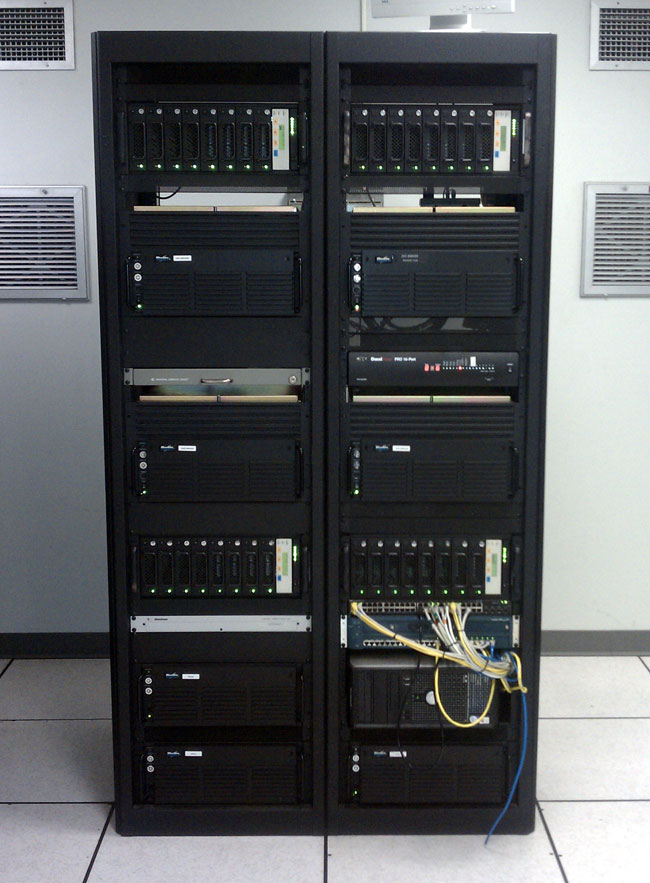
The rack room, engineering room, technical operations center, frame room, or whatever it is called, is a central part of any radio station studio facility. Normally found in a rack room are things like computer servers, switches and routers, structured cabling, telephone equipment, audio routing equipment, audio processing equipment, satellite receivers, wire termination blocks, microwave transmitters, and receivers, and sometimes even broadcast transmitters and phasors.
TOC equipment
This is a rack room for one of the clients we service. This particular facility has 6 FM and 2 AM radio stations. Several stations share the same programming, however, so more accurately, there are four formats, thus four air studios, and four production studios. The station uses AudioVault 100 for its audio playback and automation. It is probably one of the few AV100 systems still in use.
Broadcast Electronics Audiovault 100 system
There are four servers and drive bays mounted in two racks, right next to the 5 KW AM transmitter. Doesn’t seem to be an issue.
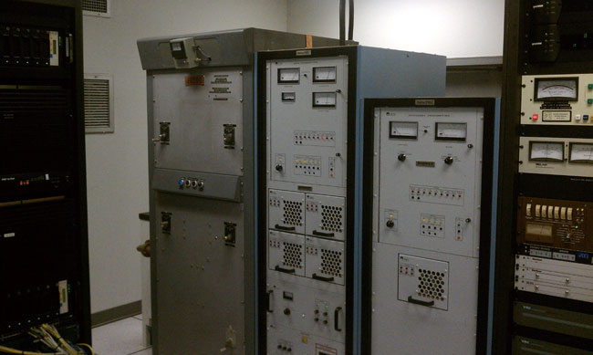
TOC AM transmitters and Gates Phasor
The studio is also co-located with one of the AM station’s transmitter sites, which always creates a special set of engineering problems. The antenna array consists of two 90-degree towers phased 210 degrees, which creates a figure eight pattern to the north and south. The studio building is in one of the main lobes of the antenna system. This means extra grounding is needed in the rack room and special attention needs to be paid to things like phone wiring and computer network cabling. This facility uses shielded Cat5E, which seems to take care of any stray RF. Of course, all the audio is balanced and properly terminated.
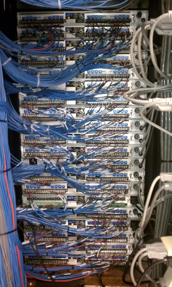
ATI DA 416 wiring connections
For audio distribution, ATI DA416 audio distribution amps are used. These are used to distribute the air signal, the program and audition audio, the satellite feeds, and remote broadcast feeds.
There are several considerations for well designed engineering rooms:
Future wiring work will be needed, there is no way that an engineer can plan for every contingency. It is difficult to plan one or two years ahead, much less five or ten. Keeping the wire conduits, raceways, trays, or troughs accessible is key to a happy existence. This can be done by using overhead trays or raised floors and good cable management.
Ground everything to a single-point ground bus. There is no such thing as too much grounding, so long as everything is bonded together. Be sure to include TELCO and service entrance grounds.
Have direct paths outside to accommodate the STL transmission line, satellite cabling, etc. If those antennas are located on the roof, have roof access in the rack room.
The environment directly impacts the life of the equipment. Keeping the rack room environmentally isolated from the rest of the facility is highly desirable. HVAC systems should be sized for the highest equipment load on the hottest day of the year. Having some type of backup air conditioning is also a good idea.
Leave plenty of room to work behind racks or on the wire wall. Cramped spaces create mistakes.
Make sure there is plenty of light to work, lack of light also creates mistakes.
Reserve some space for future growth. Extra room on the back wall for more punch blocks, and extra space for additional racks is always a good plan.
Keep the wiring neat and documented. There is nothing worse than an undocumented engineering room, it makes life difficult and in many cases, will eventually knock a station or two off the air when a wire gets snipped or pulled out.
Make the room secure. Keep the doors closed and keep unauthorized people out.
There are two conventions of thought when it comes to rack planning. The first is that all equipment should be mounted in close proximity. It is easier to run all the STL transmission lines to one rack, all the satellite cables to another, etc. Then there is the “rack assigned to a station” method, where each station has one rack with all of its processing, STL, EAS, and other equipment in it. I prefer the first method, as it makes the room look more uniform, your mileage may vary.
When done right, engineering rooms can be a great centerpiece to any facility. It is very impressive to take a client through the studio building and end up with “And this is the heart of the facility, all the radio stations run through this room…” Several larger facilities have glass walled rack rooms for just that purpose. It can be a positive attribute when everything is buttoned up.