Tower Safety Equipment

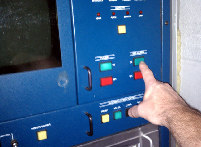
The tower climbing video that has gone nearly viral pointed out a few things.  Climbing towers is a dangerous business, best left to those who are trained for it and have the insurance.

It is true that tower climbing contractors have the responsibility to protect their own workers while working on a client’s tower.  That does not completely absolve the tower owner from liability.  It is incumbent on the tower owner to provide a safe structure to climb.  This can mean the mechanical integrity of the tower, reduction of transmitter power while workers are in high RF energy fields, and providing the proper permanently attached safety equipment on the tower itself;  Climbing ladders, ladder safety cages, rungs, elevators, and fall arresting gear.

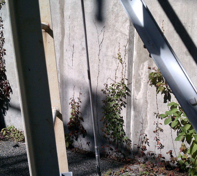
In that tower video post, I mentioned something called a safety climb.  That is a cable, usually 3/8 inch stainless steel aircraft cable, attached, about eight inches from the climbing surface like this:

Western Electric 200 foot tower with retro fitted safety climb
[

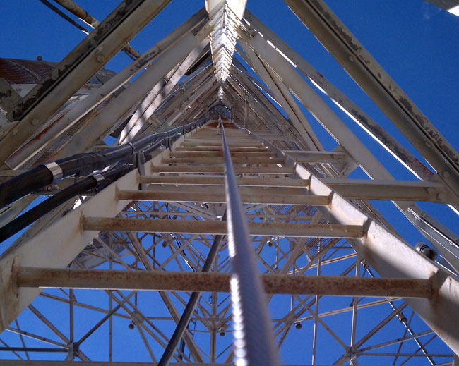
The tower itself was built in 1959 and did not have this equipment when new.  This was a retro fit kit, installed in 2003, I believe.

The tower climber wears a harness with a special karabiner attached to the front and waist level.  When climbing this ladder, the karabiner slides up the cable.  If he were to fall, the karabiner has an auto-locking or braking mechanism that would stop his fall.

Tower safety climb
Tower safety climb, attached to climbing ladder

Many tower climbers, especially those that have been in the business for a while, do not like these things.  When climbing, especially if one has long legs, the tendency is to bump your knees on the bottom of the next ladder rung.  This is because the belt holds the climber’s waist making it difficult to get the rear end out, away from the ladder the way most people like to climb.  The alternative is to climb with the knees spread apart, like a frog, which is hard on the hamstrings and quite literally, a pain in the ass.  However, if a tower is so equipped, it must be used.

I have, wherever possible, retrofitted towers with these devices.  Of course, all new towers come equipped with them. In some situations, it is not possible to retrofit towers with safety climbs, either because there is no attachment point at the top of the tower that meets the OHSA spec, there is not a climbing ladder, or it would affect the tower tuning, as in an AM tower or near a TV or FM antenna.

Hundreds of gallons of ink have been spilled by Los Federals in OHSA regulations 29 CFR 1926 and 29 CFR 1910.268(g) regarding fall protection and fall protection equipment for telecommunications workers.  In this litigious world, we live in, tower owners and or their on-site representatives should know these rules and make sure they are followed.

Where the rubber meets the road

This is the quandary that I have been in these last few months:  Time, as they say, is money.  The end product might not seem like it, however, this blog takes up a goodly amount of time.  There is the writing, research, taking pictures, editing, and whatnot.  Then there is back-end stuff, updating software, plugins, etc.

Then there is actual money expended: domain registration and website hosting.

In short, it is not free, at least not for me anyway.

I did place a few Google Ads in line with some of the content to offset the money part, which they have met that goal, but not much else.

While it is nice to have a hobby, and fun to tell stories about radio engineering, in the end, it really does not help me earn more money, support my family, advance my carrier, or my standing in the community.  The children are young, but that will not stay that way for long.  Before I know it there will be braces to pay for, a car or two, a college education, and whatever comes after that.  Not to mention my own superannuation to look forward to, with such considerations as adding to the retirement account.

There is another shift in my status coming up, with my wife off to work again as a school teacher.  I find there are not enough hours in the day to work the part-time radio engineering gig and meet the school bus to offload the children.  Therefore, something has to give, that being the part-time radio engineering gig.

I am, therefore, looking for ways to make money at home.  Developing this blog or turning it into a full-fledged radio engineering news website might be fun, but it would be much more work, and there is the rub.  I can’t do more work on this site without seeing some return.  I don’t mind working, in fact, I enjoy working, but I can’t do it for free.

So, I am open to ideas on how to monetize this blog or develop it into something else that will make some money.  The third option is to let it go…  I’d rather not do that.

Diplexed Directional AM stations

Pictures and story sent along by occasional reader John.  I worked on diplexing an AM station in 2003, it was a 5 KW and a 10 KW on a single tower.  Those power levels require using some pretty large components, however, the setup was pretty straightforward.  Each station had its own ATU (antenna tuning unit) which was then fed into bandpass filters to isolate the other station and coupled to the tower.  The ATUs were set up as low-pass and high-pass filters respective to their frequency.  The whole thing had something like 45 dB isolation, which worked(s) very well.

Doing this with a directional antenna system is another problem altogether.  Add to that the tight filter networks required as the station are only 100 KHz apart.  One saving grace, the power levels are relatively low.  The higher the power gets, the more the magnetic fields build up around the coils and mutual coupling becomes an issue.

As John notes:

1560 (WGLB) owns the site and has been there for about 8 years. Originally WGLB was in Port Washington, WI with a BTA-250M running into a 2-tower array. The city of license was changed to Elm Grove, and this necessitated a move about 30 miles south to the site shown. A 6 tower combination array was needed to protect 1550 in Lake Geneva, WI, 1550 in Madison, WI, 1550 in Morris, IL, 1540 in Hartford, WI, 1570 in Appleton, WI, 1530 in Cambpellsport, WI and 1530 in Elmhurst, IL. A 4-tower in-line array is used on 1560 during daytime, and a 4-tower parallelogram with the two south towers switched in and the North two in-line towers switched out (floated) for 1560 nighttime operation.

WGLB WJTI combined directional antenna system

Looks interesting.  Fortunately, the towers are not required to be painted or lighted, that is a big maintenance headache.

WGLB WJTI antenna field

Another thing to note; the site looks well maintained, the grass is mowed, no trees growing up by the transmitter building, the building is painted, etc.  Likely these stations are locally owned and making a modest profit, not some abandoned afterthought.

Antenna Tuning Units

Each tower has separate ATU’s for each station.  The ATU’s then feed what is likely a very tight bandpass filter for each station, which then combines the two signals and feeds the tower.  John continues:

An arrangement was designed when 1460 approached 1560 about leasing tower space for moving 1460 (ND-D) from Racine, WI north to West Allis, WI. This design is ingenious in that the array tower usage between the two stations is reversed for day-night operation! In other words, the 4-tower in-line array is used for 1460 nighttime, and the 4-tower parallelogram array consisting of the four south towers is used for 1460 daytime operation.

WJTI Phasetek antenna phasor

The 1460 pattern is pretty tight to protect 1470 at West Bend, WI approximately 30 miles north, and nighttime also to protect 1460 in DesMoines, IA. The friendly folks at Phasetek (Quakertown, PA) did the 1460 phasor and notch traps at each tower to prevent cross-modulation (inter-modulation) of the two signals feeding the towers, and after assembly on-site tuned up like a dream!

And that is saying something.  I have dealt with phasor manufacturers before, sometimes they nail it, sometimes they don’t.  Tune up can be a real challenge, which tends to put everyone on edge.

I might add that the high-tension electrical transmission towers nearby were de-tuned at 1560 years ago, and upon checking were broad enough to not require any further de-tuning at 1460! Another attribute of this design is that if something ever changes in the future, the deal can be easily be dissolved, because there is no mutual ownership of any equipment on site! It is truly one of the best “Win-Win” instances of AM station directional antenna combining I have ever seen!

It is good to see stations taking advantage of co-location these days.  It is a great way to save money on real estate and hassles with the zoning boards, who all see dollar signs when someone talks of putting up a tower.  With the amount of computing power and the lessons learned in the past 90 years or so, we are beginning to get this medium wave broadcasting thing down.

What happens next

It’s the middle of the night and the phone is ringing.  That is never good.  The transmitter is off the air.  You call the remote control and try to put the main transmitter back on the air.  No good.  The backup comes up, no problem.   Shaking off the sluggishness, you get dressed and head out the door.  The transmitter is about 30 miles away, but it’s in the middle of the night, so there is no traffic.  While driving, you are thinking of all the things that could be wrong.  The blower motor was sounding a little loud last trip.  The exciter has some reflected power.  The PA tube is two and a half years old.

Upon arrival, there are several overload lights lit, including the driver’s plate.  An investigation is in order.  You turn everything off and open the doors.  The trouble seems to be a bad IPA power supply.  There are spares on the parts shelf, so you put one in.  Put the transmitter into the dummy load.  You turn on the filament and the transmitter comes to life again.  Reset the overloads.

Broadcast Electronics FM35A transmitter ready to be turned on

Now you are standing there looking at the plate-on button.  Was it really only the IPA or was that just a symptom?  Was there something else that took out the IPA power supply?  What will happen when I press the plate-on button?  Will it come on normally or go BANG!  I hate BANG!  By the way, my tradition in a situation like this, if on a mountain top somewhere, I go outside and pee.  I give the situation one more run through the mental checklist, then come back inside and press the button.

Broadcast Electronics FM35A transmitter high voltage on button

Please excuse the blurry picture, it is hard to take a picture of yourself turning on a transmitter…