
I found this in the great clean out of 2010, Bridgeport, Connecticut. Once upon a time, I had a slightly newer version of this, I think from 1972 or so. This version is from 1964 and gives a complete rundown of most small tubes that were manufactured back then.
There is something about a well-designed, well-maintained piece of tube gear. I remember an old Collins tube console that was in a production room at a small AM station. The console went dead (the paper clip shorted the B+) and I fixed it.
I recall listening to the test recording of my own voice from a reel-to-reel machine when I fixed the console. It sounded better than I’d ever heard it, not that I have a great radio voice, by any means.
A tube is a voltage amplifier versus a transistor, which is a current amplifier. A tube does not have the same fidelity as a transistor, as the voltage reaches its peak, it gets a little fuzzy, adding some distortion and harmonics. Tube gear adds warmth, what a musician might call Timbre. The combination of fundamental frequency and varying amplitudes of harmonic frequencies allow a listener to tell the difference between a piano and a guitar playing the same note.
This is what the current crop of tube mic preamps and other tube products tries to reproduce. Several companies have come out with an amplifier design that has mostly transistors and one tube, usually a 12AX7. Unfortunately, at least in my opinion, they fall a little short. If you want to have the “tube sound,” it needs to be all hollow state.
What is intriguing to me are the schematic diagrams in the back of the book. There is one for an audio amplifier:
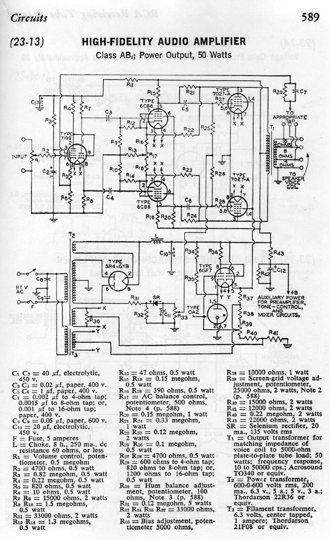
This is a single-channel unit, for stereo, it would need to be duplicated. Also, I would lose the tube rectifier in favor of a solid-state full wave bridge, which would simplify T2 somewhat. The OA2 could also be changed to a diode. Looks like unbalanced audio, which could be modified with an input transformer.
Another interesting diagram is this one, which can be used as a mic preamp:
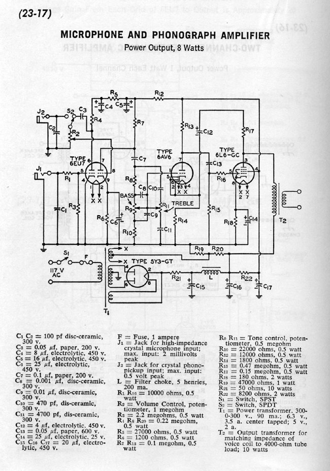
That looks like a pretty solid design, a few tweaks here or there to add some gain reduction and some type of output level adjustment and I would be a really cool piece of gear. Again, the tube rectifier could be replaced with something solid state. The output transformer would likely have to be changed to something like 600 ohms.
Couple that to something like this, the Collins 26U compressor/limiter, and one would have a great sounding microphone processor:
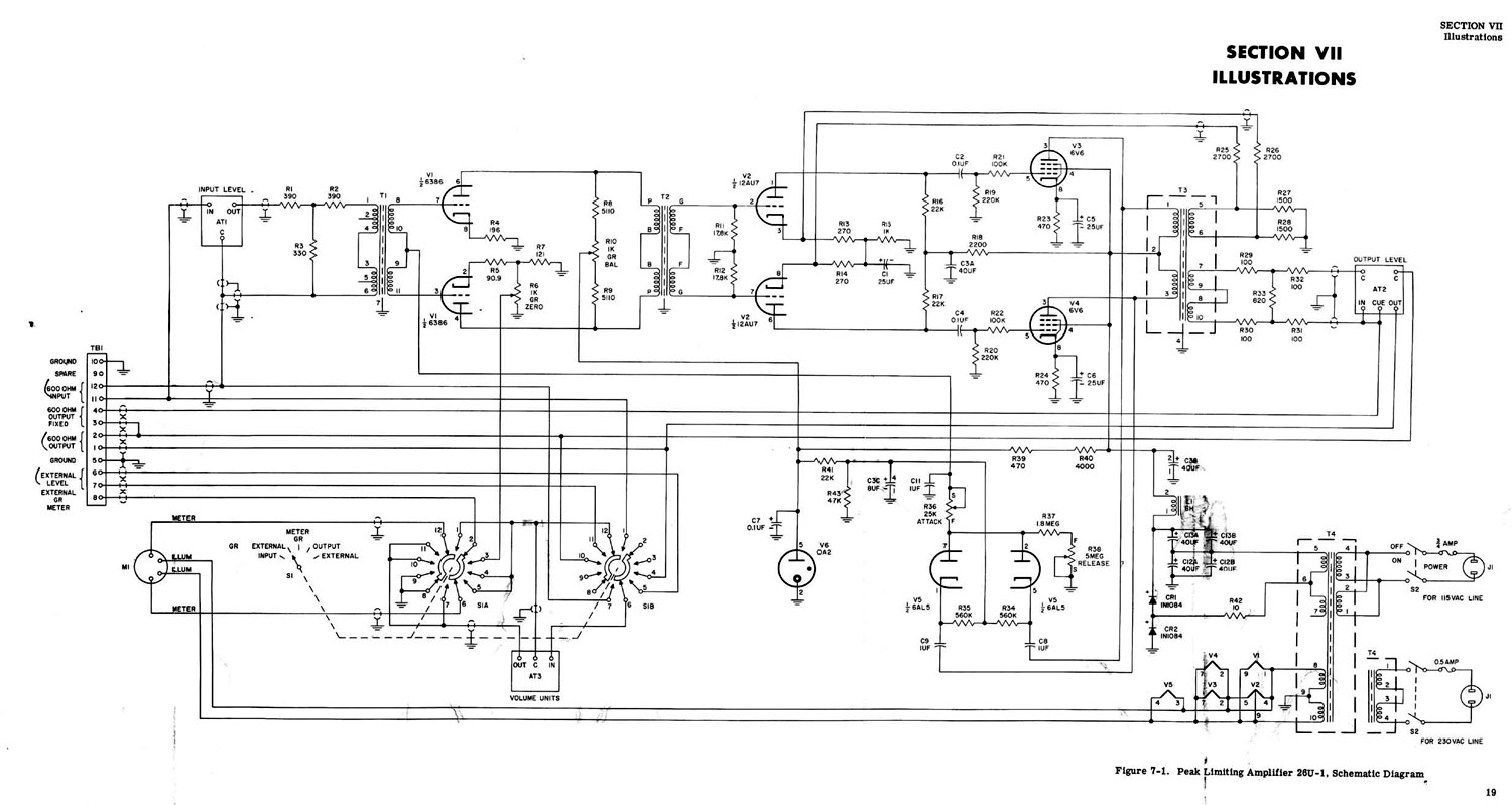
Looks pretty cool. R10 is used to balance the two plate currents. I would be interested in the transformer values, input/output impedances, voltages, etc. The 6386 tube is very hard to find these days, a good substitute would be a 5670 which is still made by several manufacturers.
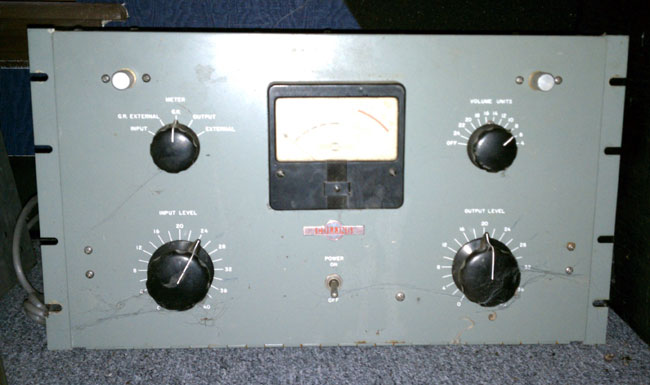
Update: This is a picture of a Collins 26-U sitting on my boss’s floor.
A great online source for tube information is Electron Tube Data Sheets.
If I have some time this winter, it may be a fun project to fool around with.

I happen to be a “Tube Sound” fanatic! The first schematic is not an “ultra-linear” circuit with the screen grids fed from the output transformer, but does have regulated screen voltage. I prefer triodes for true “listenability” and 2A3’s, 6B4-G’s, WE300B’s, 845’s, 833A’s are my favorite for audio amplifiers. The GE BT-25 used them and the sound was tops. Cathode-follower Eimac 304TH triodes drove WL5891 triode modulators making it one of the best sounding 50 kW transmitters I have ever heard! The second circuit shown, I actually built when I was 12 years old and with the inverse feedback shown came close to my 6B4-G amplifier, but not as good. It seems that tube audio is still going strong with the “audiophiles” and will probably continue. Too bad the broadcast equipment manufacturers have thrown in the towel!
As to the 6386, it was developed by GE and was first used in their popular “Uni-Level” compression amplifiers for broadcasting. Gates quickly copied the idea and used this tube in their STA-LEVEL compression amps. Collins also jumped on the bandwagon. I could easily get 30 dB of compression with extremely low distortion with the GE Uni-Level and the Gates STA-LEVEL amps. I have tried (and used) 2C51 JAN surplus tubes and they are very close to the 6386 and work well in these circuits..
The GE BTA25 transmitter was simply the best sounding transmitter I have ever heard. The WPTR unit had been modified to take 833A’s in the RF IPA section. It was truly sad when we had to disconnect it.
When it comes to audio processing these days, the general idea is to digitize it, then slice it, dice it, smash it, rotate the phase, subtract some bits, and then send it off to the transmitter. Everyone oooos and ahhs at the wonderful new processor. Of course, these same people think an MP3 sounds good too. Very few of the so called professional have any idea what good analog audio sounds like, they are so used to hearing crap from there computer speakers.
Back in the day of Sun Records, when everything was recorded with minimal “processing” and mixed down to mono on tube gear, like some of the King’s early recordings, no one gave a crap about any of this. The recording engineer eq’d the record, broadcast processors were limiters designed to ride gain. And guess what, it sounded great! That is why radio became so popular, it was good music, well produced and well reproduced and transmitted over the air. Something that today’s processing “Gurus” need to think about.
As far as the audio limiter goes, I am going to fool around with making something this winter. I have a stock of tubes including most of those in the 26U diagram. 2C51 tubes are relatively inexpensive. I think the rest of the stuff I can come up with by just scrounging around.
In 1968, I built a copy of the Gates STA-LEVEL, except with 6005 GE “5-Star” output tubes, and a UTC “CG” output transformer. This is when I used 2C51 (Tung-Sol) tubes. I also bought a GE 6386, and couldn’t see much difference. The station I worked for at the time (while in college) had a GE “Uni-Level” on the phone patch so callers calling into the station for contests could be put on the air without “gain riding”. At that time the GE Uni-Level was no longer available, and the station bought my built unit to complement the Uni-Level for the recording studio section of the station!
And as to the magnificent BT-25, AMEN!
i am looking for a collins 26 u limiter do you have one (redacted, contact site owner) george
Collins 26u! I buy this old tube stuff and microphones for audio use in recording studio. I’m currently looking for some Pultec EQP-1A’s. If you find any of these classics in the old equipment room please contact me.
Nice someone remembers where the 6386 started. Thanks for that info.
love radio and have worked many stations in the meadowlands of Jersey. mappeeme@yahoo
One could build something almost the same as the BT-25, or Gates SA-39B, but with vastly lower distortion and the ability to compress more if needed without overload. The gain control element is a triode pair where the transconductance changing with bias is used for gain control. All tubes see a fall in gain in low currents, and it’s what creates the even-order harmonics in single-ended stages. But that same gain shift with current causes distortion of the signal. In push-pull, like the gain control circuit here, the symmetry of two tubes gives odd order distortion, coming from the lower gain near zero somewhat like gradual cross-over distortion. If that push pull pair was made inter a differential pair (like a balanced modulator), with the output between the plates as now, but control signal to one grid and adjustable bias to the other, and the audio input signal feed to the cathodes by the plate of a DC-coupled triode (cathode to a cleanly regulated negative supply), the signal would be balanced out when the two triodes had equal bias. Gain would start at maximum with the tubes biased unbalanced and gain reduction at low distortion would occur as the control voltage shifts bias towards balanced.
Free software is available to use a simple Mac or PC audio chip/card or USB/Firewire interface as a low distortion audio generator and FFT audio spectrum analyzer. Performance can easily beat the audio distortion measuring equipment typically find in broadcasting (or was when audio proofs were routine). If not using one of the audio cards with a higher sampling frequency, alternate test signals can show issues with in-band distortion products. Two high frequency tones mixed with one low frequency make a good intermodulation distortion test. Seeing the audio spectrum is very revealing. Doing simple THD testing, I was shocked to see that even with spurious blips from internal switching supply noises, the simple walkman style line level input on an ordinary laptop I tried was able to see the second and third harmonics of a low-distortion oscillator at about -94dB. (under .004% total harmonic distortion). It’s wise to add an audio isolation transformer, attenuator, and something to clamp excessively high voltages to avoid input damage from mistakes.
Tube distortions can be brought way way down with proper circuit design although it is more complex when transformers are in the loop. As for tube sound, it’s not so much that tube distortion sounds good, but it is generally not too unnatural. Transistor distortions (even measuring less) often sound far sound worse. That’s because they’re not gradual non-linearities, soft compression of peaks etc. The most offensive transistor distortions occur when a high gain stage has its gain partly determined by it’s load impedance and it is driving an output stage where the input impedance varies radically when devices switch on, switching between devices occurs, gain varies with current, and input reflects a later load like a reactive speaker or transformer that becomes reactive or has a resonance. Many transistor power amp transfer functions are full of tiny but offensive kinks and bumps in the middle compared to gentle rounding off at the ends with tubes. And of course when over driven, hard clipping is also harder to tolerate. It’s easier to see the more offensive distortions on a FFT analyzer since they produce higher order harmonics and intermodulation.
A mix of tubes and transistors can work really well. A DC coupled power MOSFET source follower can easily drive an audio power tube grid with excellent bandwidth and impedance so low there’s no added distortion when grid current is drawn. Advanced drive circuits can modify the drive to linearize a tube from transconductance variation with current and screen-induced distortions. Restoring classics is fun. Modern design and tubes can be a rewarding mixture too. And a FFT software based analyzer can make performance changes easy to see. Of course our ears make the ultimate judgement.
@DBug, or a Raytheon RM-10, which I will post the schematic for in the near future.
Even with the generally higher distortion, much of that old gear is a pleasure to listen to. Some of the processing may have been pumping or breathing, but it wasn’t so fast and aggressive. Sometimes it seems things could sound much better than they do, and it leaves people guessing the reason. Competitive pressures even with disc mastering? Just not caring? Or something more sinister, making one thing sound worse to push a new technology (sort of like the old faithful razor blades losing the ability to hold an edge when a new variety comes out). I’m wondering if some deliberately made CDs less dynamic to give people a reason to buy audio on DVD (which was likely pushed mostly because of copy-restriction). Sure a higher sample rate and more bits is better, but CDs are capable of sounding good. Vinyl is capable of sounding good…
http://www.youtube.com/watch?v=3TlQo9k827c