The General Electric T1000C Stereo Receiver

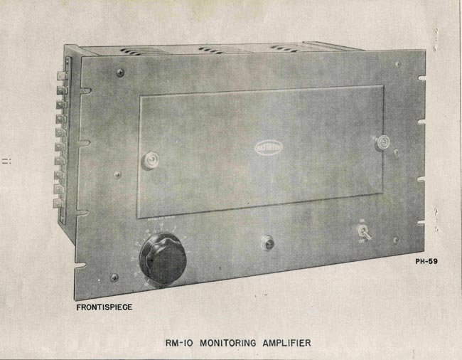
My parents had one of these units on the side table in the dining room. My father put up an FM antenna outside on the roof so he could listen to more stations. In the early 1960s, there were not as many around as there are today. Our house was on the wrong side of a hill for the NYC stations, although Peekskill seemed to come in just fine. What is fascinating to me is the timing and cost. These stereos were made in 1963, not long after the Zenith/General Electric FM stereo system was adopted and first broadcast on WGFM (now WRVE) in Schenectady, NY (June 1, 1961). Not every FM station rushed out to install the new system.

General Electric T1000C Stereo receiver marketing

For a bit of a reference, $180.00 in 1963 is worth $1,868.65 in 2025. At that time, my father was an installer/repairman for New York Telephone. My mother was not working and six of us lived under one roof. That was quite a bit of money for an AM/FM radio.

The radio was normally tuned to 100.7 WHUD, which initially went stereo in 1972. Other stations that could be received: WGFM, WROW-FM, WSPK, WEOK-FM (now WPDH), and WGFH (later WINE-FM now WRKI).

General Electric T1000C stereo (Walnut cabinet)

I purchased this one on eBay for $70.00. It turns on (in fact, it did not turn off), there is a hum, the pots are scratchy, etc. However, if I tune it to one of the local AM stations, I can hear music under the loud 60-cycle hum. In other words, it works! So, I spent time fixing all the defects and enjoyed some nostalgia. According to this date stamp, the wood enclosure was made in January 1963. I would think the rest of the unit was made about the same time, which means this is one of the first radios in this model. This may have been manufactured in Bridgeport, CT, or Syracuse, NY. The serial number is missing from the back of the chassis.

Crushed capacitor

The main source of the hum appears to be this capacitor, which clearly has seen better days.

The on/off problem was the selector switch, which stuck in the on position because it was gunked up with dried-up lubricating oil and dust. I cleaned it with denatured alcohol and DeOxit.

Production date; January 1963.

The parts list included about $15 worth of capacitors, $1 for a new rectifier diode, a $7 telescoping FM antenna from Amazon, and $6.32 for two PLT 12 6.3 volt miniature lamps for dial light.

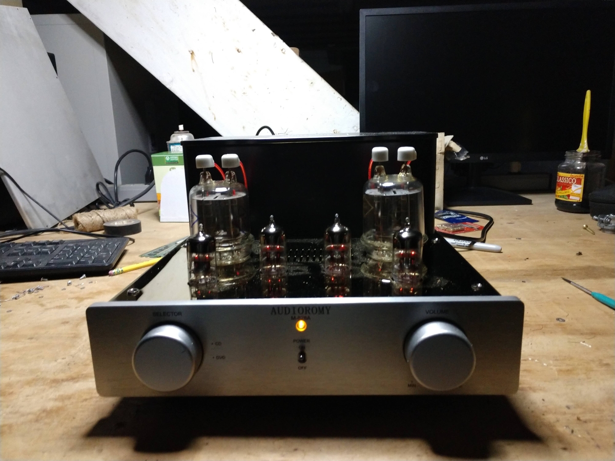
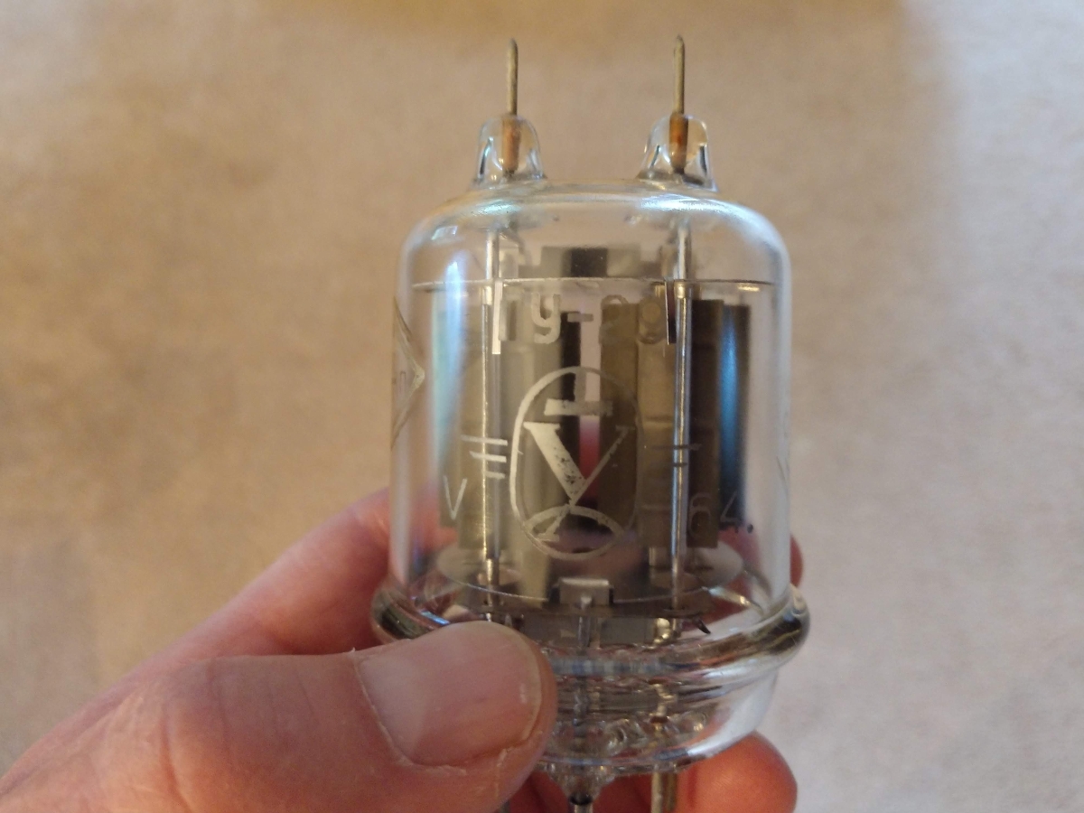
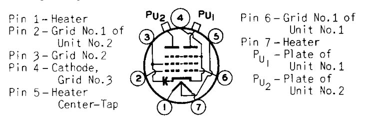
All of the tubes look to be the original GE units. After the recap, I turned it on and there was nice sounding AM, but no FM. The FM RF section has a triple triode (V2) which is the AFC, 10.7 MHz Oscillator, and mixer. This tube was loose in its socket and needed to be reseated. After that, everything worked.

GE T1000C chasis

All of the pots were scratchy. I cleaned them with DeOxit and worked them back and forth many times. After a while, they all are working.

FM Stereo receiver MPX decoder block diagram

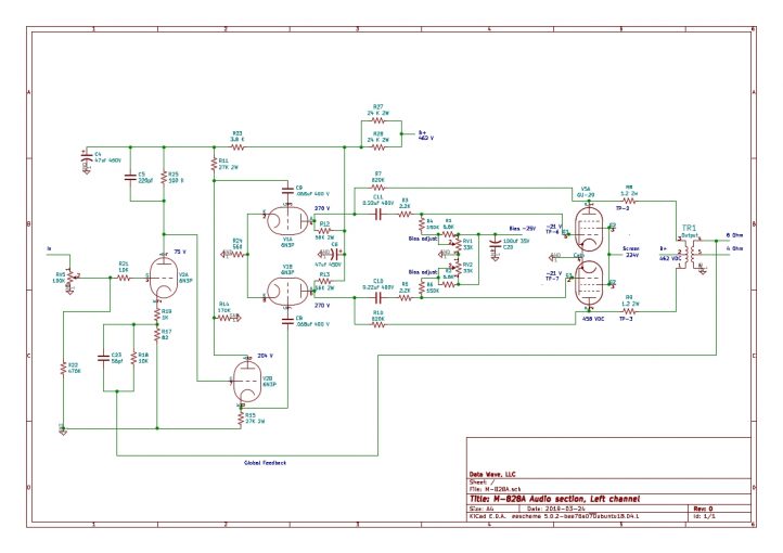
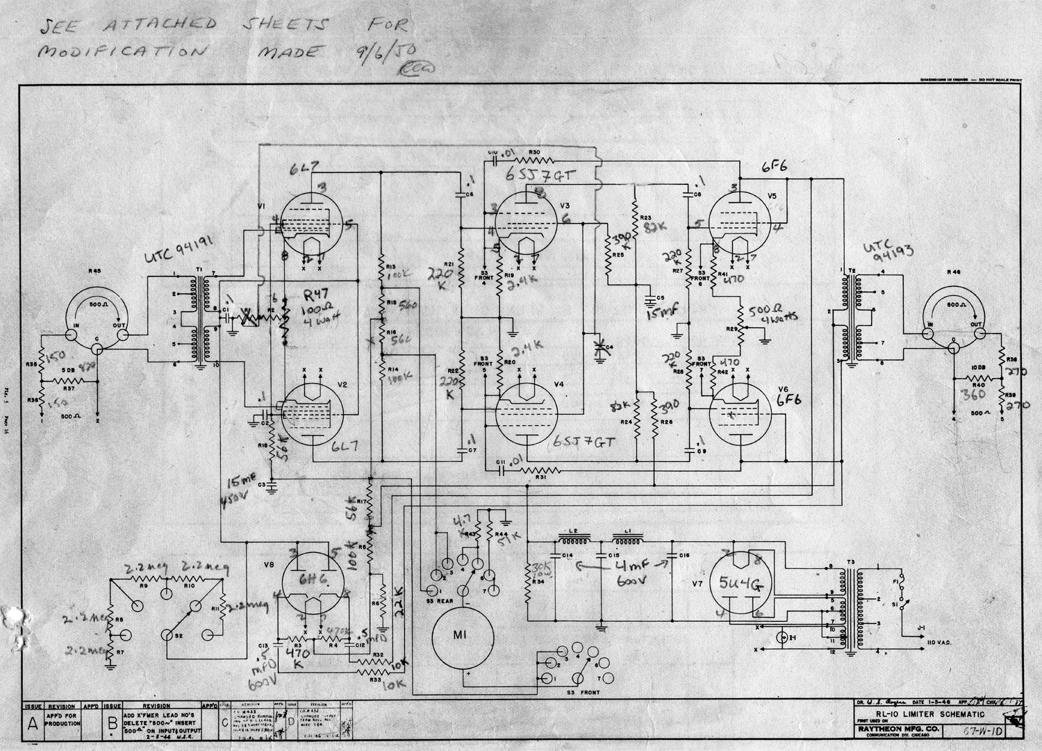
I found a Sam’s Photofact (basic service manual) on this set. What is very interesting is the schematic for the multiplex receiver. This section decodes the L+R/L-R signals and produces the stereo audio. Unlike modern FM stereo receivers, in which the broadband multiplex signal is fed into one side of a chip and the discrete L/R signal comes out of the other side, the signal path through the various processing stages can be followed.

GE T1000 MPX decoder schematic diagram

The broadband MPX signal comes from the IF stage via wire #27. The signal is amplified by V6. The L+R (20 Hz to 15 KHz) or mono signal goes through a low-pass filter L17/C40; the 3dB cutoff should be around 16-17 KHz. The L-R and 19 KHz pilot goes to wire 34, thence through a high-pass filter C37/L16/C38; the cutoff should be 20 KHz or so. The L-R and 19 KHz pilot are Amplitude Modulated subcarriers on the FM signal. Wire 38 routes the MPX signal to V6 which recreates the 38 KHz subcarrier by doubling the 19 KHz pilot. This is filtered by a bandpass filter C13/L14. The L-R and the 38 KHz subcarrier are sent to the product detector.

Diode product detectors X4 and X5 (1N541) demodulate the lower sideband (23 – 37.98 KHz) and the upper side band (38.02 – 53 KHz) respectively. Those signals are summed in the matrix subassembly K4 with the L+R. Mathematically, the results are:

The Left and Right audio is then sent to the first audio stage V7 through a deemphasis network. If no 19 KHz pilot is detected, no 38 KHz carrier is recreated and this stage remains silent. In other words, you have to find an FM station in mono first, then flip it to stereo to see if there is enough signal to decode the L-R. One of the limitations of the first generation of FM stereo receivers. Newer versions of this set have a stereo light, or “Stereo Eye” so the listener knows when stereo reception is possible.

The front of the cabinet is covered with glass, which I cleaned with soapy water. The glass has part of the gold leaf trim rubbed off. I think this radio got a lot of use.

I let the knobs soak in soapy water overnight then cleaned them off with an old toothbrush. I believe that this radio was once in a smoking environment, based on the amount of yellow, gooey substance covering everything. I ended up disassembling the entire unit to clean it. I used a paintbrush and the shop vac to get all of the dust out of the cabinet.

General Electric T1000C disassembled

The speakers and speaker cones are in good condition. The speaker cabinets needed a little work; in both cabinets, the fronts (the part that is seen when both speakers are “closed”) were popping off. I had to glue a bit of wood back together and fix the metal holding brackets. The cloth on the speaker side is a little faded.

General Electric T1000C restoration complete

The wood finish is in good shape with a few scratches and dings. I decided to use Howard Restore-A-Finish. This is not the same as stripping and refinishing but rather repairing the existing finish. There was a water ring on top of the cabinet, which was removed with the Restore-A-Finish and light use of steel wool.

Three power supply capacitors, held down by a ty-base glued to the chassis

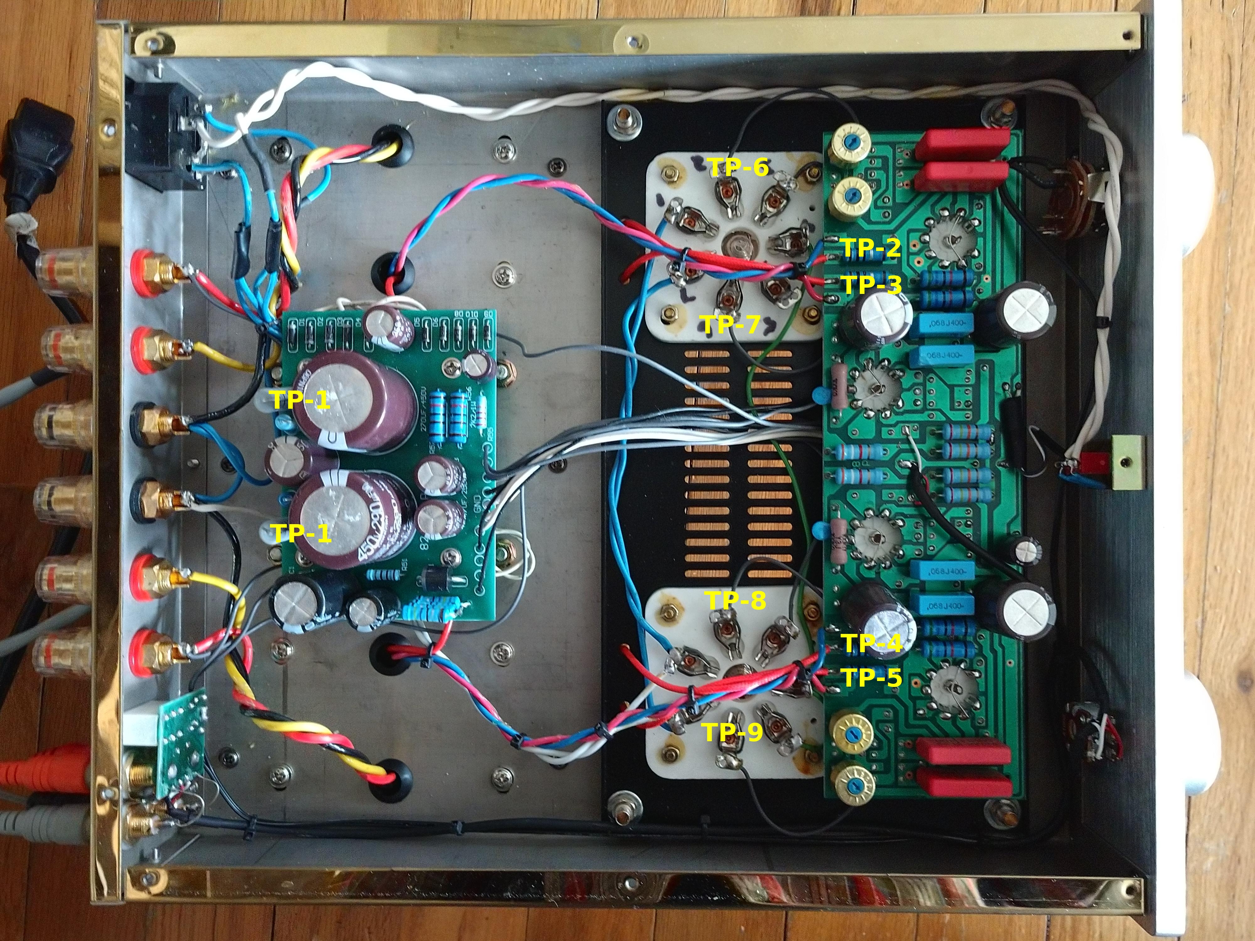
Reassembly went about as expected. I glued these tie bases to hold up the new capacitors.

The receiver is fairly sensitive and the dial is accurate. There is an alignment procedure in the repair manual, but I think everything is working as it should. I have spent enough time trying to fix things that are already working to know that for a 1963 tube receiver, this is good enough. Perfection, as they say, is the enemy of everything else.

So, how does it sound? Pretty darn good, as it turns out. I am working on a brief YouTube video with some religious music (I’ll post it when it is done). On the FM side, I can get WAMK, WBPM, WKXP, WJUX, WDST, WPDH, WFSO, and WPDA clearly with the whip antenna on the radio. AM, I hear WGHQ and WJIP.

I can hear the old man now, humming along to his favorite tune…

Analog Sauce: The Audioromy M828-A

AKA: Tube amp part II

Audioromy M828A on the bench

I have been fooling around with this amplifier for a month now and I have to say, it is rather fun.  There are a few hazards when purchasing Chinese HiFi (ChiFi) equipment.

The first thing to note; several places such as Ebay and Amazon list this as a single-ended class A amp. That is not true, it is a double-ended class AB amp.  I confirmed this by measuring across the two sections of the output transformer.

The second thing to note; this amp came wired with a fuse on the hot side of the AC mains and the power switch on the neutral.  Switched neutral (AKA earth, return or ground) wires are a hazard, so I rewired it, putting the switch after the fuse on the hot side after the fuse.  Another safety thing, the edge of the metal chassis was not de-burred.  I took a flat file to it and removed the burr, thus avoiding any future lacerations.

Finally; there is no manual provided with this unit.  There are a few sets of instructions on how to re-bias after tube replacement which is technically correct but not the best way to go about it. Those instructions direct the user to solder a low-value resistor from cathode to ground and then measure the voltage drop on that resistor to calculate plate current. While this is a valid way to deduce plate current, the power output tube has two tubes in one envelope and the cathodes are tied together. The plate current can be calculated for both sides, but there is nothing indicating that the two sides are balanced and one of the tubes can red plate. This was also noted in those instructions found online.

That being said, I thought I could type up a set of directions that are more suited for this amplifier.  But first, read this dire warning about working with High Voltage:

This amplifier has lethal voltages present during operation. It is possible that lethal voltages can be stored in certain components for days after the amplifier has been turned off and disconnected. By removing the protective covers, those components will be exposed and you may come in contact with them if you are not careful.

If you are planning to service this amplifier, it is vital that you have basic electronics and electrical knowledge. This includes all applicable safety procedures for working on high-voltage components.

If you do not have this knowledge, please bring this amplifier to a qualified electronics technician or repair shop for service.

I am not responsible for any injuries or damage suffered to yourself or others if you decide to undertake repairs to this equipment.

I acquired a few of these Ulyanovsk GU-29 tubes and decided to try them out.  The maximum plate dissipation for this tube is 40 watts with bulb temperature of 175°C and ambient temperature of 20°C.  I measured the bulb temperature at 142°C and the temperature in my living room ranges from 20ºC to 32ºC (68ºF to 90ºF).  I could, in theory, bias these tubes for a higher plate dissipation, if I wanted to.

Ulyanovsk GU29 tube, made in the USSR
Ulyanovsk GU29 tube, made in the USSR, circa May 1964

I asked my Russian friend what the assembly line person or factory manager might think if he or she knew that the tube made in their factory would end up being used in a home audio amplifier owned by a guy in New York.  She said, “They would have a stroke.”  Ulyanovsk had and still has a heavy military presence, thus they likely assumed that all their products would be used by the Soviet Navy or Army.

Being that this particular tube sat around in a warehouse for 55 years, it was slightly gassy.  When I first turned the amp on, there was a distinctive pink glow and a couple of small internal arcs.  It probably would have been a smart idea to light up the filaments for several hours before applying plate voltage.  Unfortunately, I had that idea after I’d already energized the amplifier.  In any case,  I increased the bias and reduced the plate current.  After a while, things settled down and I got to work re-biasing the amplifier.

To re-bias the amplifier after new tubes have been installed, some initial data needs to be gathered.  Basically, this procedure involves measuring the resistance of the plate circuit, then measuring the voltage at the output of the plate voltage supply and the voltage at each of the plate terminals on the power amp tube.  The plate voltage on this amplifier is +460 DC or so voltage above ground potential.  Obviously, this is a dangerous voltage and if you are not familiar with working on high voltages, do not attempt this procedure.  The best way to measure these test points is to use clip leads; turn the amp off, let the capacitors discharge, place the clip leads on the appropriate test points, turn the amp on, make the measurement, then turn the amp off, repeat as necessary.

After the replacement of the power tubes (V-5 and V-6), the bias for those tubes should be checked and adjusted as follows:

A. To measure plate dissipation as set by the factory, perform the following steps:

1. With the amp completely turned off and disconnected from the AC mains, remove the bottom cover. Ensure that the large power supply capacitors are discharged to the ground. With an accurate ohm meter, measure from the exposed lead on L-1 (TP-1) on the power supply board to the input to the anode resistor (R-21 or R-22 in the schematic diagram (TP-2, TP-3, TP-4, TP-5)) for each tube (four measurements total). Make a note of those measurements. For reference, my amp measured between 163 to 165 ohms.

2. Reconnect the amp to the AC mains and turn on the power (be sure to read the dire warning about high voltage above). With an accurate DVM, set to DC volts scale, carefully measure the voltage on the exposed lead of L-1 on the power supply board to the ground, and make a note of it. This is the B+ voltage for the amplifier. Carefully make another measurement between the input of the anode resistor (R-21 or R-22) and ground (four total measurements, likely to be the same), this is the plate voltage for the power tubes. Make a note of that as well.

3. Subtract the plate voltage from the B+ voltage. For my amp, this was 462 VDC 458 VDC = 4 volts. This can also be measured between TP-1 and TP2 through TP-5 See charts 1 and 2 below. This is the voltage drop. Using ohms law, calculate the plate current for each section of the amp:

Voltage drop ÷ resistance = plate current or 4.17 VDC ÷ 163.2 ohms = 0.0255 amps (25.5 ma) plate current.

Using ohms law, calculate the plate dissipation for ½ of the power tube:

Plate voltage × Plate current = Plate Dissipation or 458 V × 0.0255 amps = 11.7 watts.

Add both sides of the tube together for the total plate dissipation.

Chart 1: Left power tube, V-5

Test points Resistance Plate voltage (TP-2/3 to gnd) B+ (L1 or TP-1 to gnd) Voltage drop Plate current Dissipation
TP-1 to TP-2 163.2 ohms 458 VDC 462 VDC 4.17 VDC 25.5 ma 11.7 watts
TP-1 to TP-3 163.9 ohms 458 VDC 462 VDC 4.16 VDC 25.3 ma 11.6 watts

The total power dissipation for V-5 is 23.2 watts or 77% of the maximum for the stock FU29 tube. That is slightly above the commonly recommended safe range of 70% of the maximum, but it is tolerable.

Chart 2: Right power tube, V-6

Test points Resistance Plate voltage (TP-4/5 to gnd) B+ (L1 or TP-1 to gnd) Voltage drop Plate current Dissipation
TP-1 to TP-4 164.4 ohms 458 VDC 462 VDC 4.23 VDC 25.3 ma 11.6 watts
TP-1 to TP-5 164.8 ohms 458 VDC 462 VDC 4.14 VDC 25.1 ma 11.5 watts

The total power dissipation for V-6 is 23.1 watts or 77% of the maximum for the stock tube.

Test points for tube bias adjustment

Pin out, 829B tube
Pinout, 829B tube

B. When replacing the power tubes, it is recommended that they be replaced in kind in pairs.

Step 1: Increase the tube bias (measured on pin 2 or 6 of the power tube) to -25 VDC and check the plate voltage drop on both tubes. Increasing the bias will reduce the plate current and thus the plate dissipation.  This will be noted as a decrease in the voltage drop.  A good starting set point would be 50-60% of the normal factory plate current (Vd ÷ Plate R) setting. The voltage drop can be measured directly by connecting the positive lead to TP-1 and then measure TP-2 to TP-5 with the negative lead. Use clip leads, placing them on the test points with the amplifier turned off.  Be extremely careful; these test points are +460 VDC above ground when the amp is energized. Read dire voltage warning above.

Step 2: Turn off amp, discharge power supply capacitors, replace tubes.

Step 3: Allow the new tubes to burn in for approximately 3-5 hours with reduced plate dissipation, make sure that the amplifier is connected to a suitable load on the speaker output terminals.

Step 4: With the DVM connected to TP-1 and TP-2, slowly bring the bias down until the plate circuit voltage drop approaches the values for the old tube.  Repeat procedure for each plate circuit (TP-1 to TP-3, TP-1 to TP-4 and TP-1 to TP-5). Recalculate plate dissipation. Be sure not to exceed plate dissipation of the tube! It is best if the tube is biased to run at about 70-75% of the maximum plate dissipation.

Step 5: With the amp fully warmed up, turn out all lights and observe the plates of both tubes for any signs of red plating.

Step 6: Carefully measure the balance between the two plate outputs of each tube by placing the DVM leads on TP2 and TP3 for V5 and TP4 and TP5 for V6. Alternatively, the test leads can be placed directly on Pu-1 and Pu-2 of the power tube under test. Between these test point pairs, the DC voltages should be zero or close to it. Note; there will be some fluctuations in the hundredths or thousandths volt ranges. Very, very carefully, adjust the bias control pots until the voltmeter reads zero or as close as you can get to zero.

Step 7: Recheck the plate dissipation for both sides of the tube, make sure that they are closely matched and not exceeding the maximum plate dissipation for the power tube in use.

I discovered several things during this process; it is very easy to red plate one side of the tube while adjusting the bias controls.  Fortunately, I noticed this right away and was able to stop the red plating quickly.  The Ulyanovsk tubes seem none the worse for wear.  As Alex Ovechkin says “Russian machine never breaks.”

Next, the schematic diagram I posted previously is not correct for this version amplifier.  There are two bias voltage controls, one for each grid.  There is no balance control, the tubes are balanced by making very careful adjustments to one or the other of the bias controls.  Updated schematic diagram:

Audioromy M-828A schematic diagram

When the amplifier is properly biased and balanced, the distortion figures should be very low, less than 0.5 to 1% THD at full power.  It makes a big difference.

The point of all this is to 1) have fun, 2) perhaps learn something about tube (or valve) circuits and 3) listen to really clean, good-sounding audio.

The Raytheon RL10 Limiting Amplifier

Update: Apparently this is quite interesting to a number of people.  I have rescanned the manual, properly compressed it and which you may find it here.

Found this manual at one of the older transmitter sites:

Raytheon RL10 limiting amplifier manual cover

The entire manual is available for your reading pleasure here: Raytheon RL10 limiting amplifier

As this is an older design than either the Gates Sta level or the Collins 26U, it may not be as useful to tube audio enthusiasts.

Raytheon RL-10 Schematic diagram

The main issue with the Gates and Collins unit is the GE 6386 remote cutoff triode used, which were great tubes, but very difficult to come by these days.  This design calls for a 1612 or 6L7, which is a pentagrid amplifier.  Feedback is provided by the screen of the following stage, a 6SJ7GT.  Anyway, perhaps it will give somebody some idea of how to make a good tube compressor limiter.

The Raytheon RM-10 Monitor Amp

I found this manual from 1946 in the drawer at the WICC transmitter site, which is a sort of time capsule due to its inaccessibility. I figured I would bring it home and scan it, then return it to the file drawer out on the island.  Step one is done:

Raytheon RM-10 Monitor Amp

This is a cool little monitor amp, capable of driving line-level or speaker outputs up to about 10 watts or so.  It could be used as a front or input stage for a larger audio amp.  By the way, 10 watts is a lot more than it seems, if using efficient speakers to convert that power into sound waves.  Specs show total harmonic distortion is between 0.6 to 2 percent depending on power and frequency.  Lower power output levels net less distortion.

Schematic is pretty simple, a pair of 6L6’s in push-pull for the output.   Inverse feedback into the previous stage via the output transformer.  Click on image for higher resolution.

Full manual and parts list is available here.

Now I just need to get the manual back out there.