I love wire. I know, what a geeky thing to say, but it is true. For no reason that I can explain, I have always been fascinated with wire, cables, and electricity.
Category 5e and up cabling is amazing stuff. Designed for computer applications, it can fulfill a wide variety of roles in radio and television stations, mostly because of its high bandwidth capacity. Category 5e cabling has a 100 MHz bandwidth, category 6 bandwidth is 250 MHz, with 6a (augmented) being 500 MHz. AES/EBU audio uses ATM and requires from 4-26 MHz bandwidth, depending on the sample rate (the highest sample rate is 200 KHz). Category 5e cable has a minimum common mode balance of -60 dB, which makes it nearly impervious to RF, electrical noise, mutual interference, and other noise issues.
Further, each pair in category 5e or 6 cables has a different twist rate, to reduce cross-coupling between pairs.
Here is a chart of electrical characteristics for Cat 5e, Cat6, and Belden AES/EBU cable:
| Category 5e | Category 6 | AES/EBU* | |
| Impedance (ohms) | 100 +/- 10% | 100 +/- 10% | 110 +/- 20% |
| Bandwidth (MHz) | 100 | 250 | 52 |
| DC resistance 1K Ft (ohms) | 27.12 | 27.42 | 23.68 |
| Capacitance per Ft (pF) | 15 | 15 | 12 |
| Velocity factor (%) | 72 | 72 | 76 |
| Common Mode Balance (dB) | 60 | 63 | 30 |
| NEXT | -44.3 | -53.4 | – |
| Configuration | UTP | UTP | SPT |
| Wire | Solid | Solid | Stranded |
| Gauge | 24 | 23 | 24 |
* Belden 1800F
Specifications above are for Belden cabling, but are typical for high quality category cabling available from other sources as well.
Although the AES/EBU cable specifications call for 110 ohm impedance cable, that specification is pretty loose, calling for +/- 20%, which means 88 to 132 ohm cable will work well. Category 5e and 6 cable is 100 ohm impedance, +/- 10%, which translates to 90 to 110 ohms, nominal.
Category 5 and 6 cabling can also be used for analog audio, RS232 and RS485 applications. One area of caution, however, is for T-1 or fractional T-1 services. On the DS side (between the smart jack and the CSU), T-1 type service runs 3 volts peak to peak. That is much higher than AES/EBU or ethernet, which run 1 volt peak to peak. As a result, cables in this type application should be 22 gauge or higher to reduce emissions from the cable.
Shielded category cable is available in Cat5 and 5e. The shielding acts to reduce emissions from the cable in low noise environments. It can also act to reduce RF fields around the cable pairs, so long as the proper cable terminations for shielded cable (RJ-45 or more properly 8P2C connectors) are used and installed correctly. The shield must be connected to a ground on at least one end. I know a facility that has all shielded Cat5 cable, but they used standard RJ-45 connectors, so both ends of the shield are floating, which completely defeats the purpose of the shield.
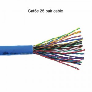
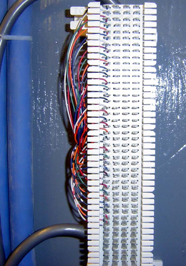
25 pair category 5e cable is available for trunk cabling between studios and the technical operations center. For one studio project, I purchased pre-made cables with RJ-21 connectors on both ends. Those connectors were then plugged into KRONE LSA-PLUS blocks. Cable, connectors and blocks were all 100 ohm impedance, category 5 equipment. Since we did not have to strip any insulation or punch down any wires, we pulled and terminated the studio to rack room trunk cables for five air studios and three production rooms in one morning. This greatly sped up the studio build out process.
The studios and TOC use SAS 32KD (Sierra Audio Systems) audio routers and Rubicon SL consoles, so most of the audio is AES/EBU. There are, however, several analog audio sources that are included in this system, things like telephone caller audio, off air monitors, satellite feeds and remote broadcast sources.
This facility is located about 1 mile away from a 5 KW AM station on 850 KHz. Several concerned people commented on the possibility of RFI on the cabling. In the five years since that project was completed, there have been zero issues with the cabling or the audio quality.
One thing to consider in these installations is the length of the cabling and the sample rate being used across the network. The capacitance per foot is the deciding quality in cable lengths. This is because capacitance, which is the ability to store an electrical charge, will begin to distort the signal (turn it into a saw tooth waveform) in the cable if certain lengths are exceeded. A good way to calculate maximum cable runs is thus:
Most professional AES/EBU devices sample 24 bits per channel, if the sample rate is 48 KHz, the 24 bits x 48,000 Hz = 1,152,000 bits per second per channel. For stereo, as most applications will be, that is doubled to 2,304,000 bits per second, or 2.3 Mbps. There is some overhead in an AES/EBU signal, so, for arguments sake, we will call it 4 MHz.
In this facility, the sample rate is locked at 48 kHz by a master clock. The longest cable length is 145 feet, which adds (15 pF x 145 Ft) up to 2,175 pF capacitance. From the chart above, we know that Cat5e has a resistance of 27.42 ohms per 1000 feet, or 0.02742 ohms per foot. That works out to be 145 feet x 0.02742 ohms = 3.9759 ohms.
To calculate the capacitive reactance, the following formula is used:
Xc= -1/(2π FC)
Where Xc is the capacitive reactance, F is the frequency in Hz and C is the capacitance in Farads.
Therefore Xc = -1 / (2 x 3.1415 x 4,000,000 x 0.000000002) = -19.89 ohms.
The characteristic impedance of Cat5e and Cat6 is 100 ohms. The DC resistance is 3.97 ohms and the capacitive reactance is -19.89 ohms, make the circuit impedance of a properly terminated cable 145 foot cable 84.08 ohms.
The design formula for a low pass filter is thus:
fc = 1/(2πRC)
Where fc is the cutoff frequency, R is the resistance and C is the capacitance.
Therefore, fc= 1/(2 x 3.1415 x 3.9759 ohms x 0.000000002 farads) = 20,014,958 Hz or 20 MHz.
Generally speaking, one should try to keep the capacitance below 2500 pF in a 10 Mbps circuit. Belden datatwist 1212 cable has a 4.0 dB insertion loss and a 23.0 dB return loss per 100 meters (328 feet) at 4 Mhz.
145 feet is well within the limits of this cable for AES/EBU applications.
Further, all cable circuits need to be properly terminated to reduce return loss. Using common impedance wiring blocks, connectors and terminations help keep return loss to a minimum. Stranded wire works better in applications where cabling may move. There are Cat5e and Cat6 stranded cables available.
As data transfer rates approach that of RF, ethernet, digital audio, and RF are going to seem more and more similar. 1000 Base T (1GBT) and 10000 Base T (10 GBT) networks are coming.


Great article and really great site. I have been in Broadcast IT and crossover to engineering for around 25 years. I have recently started working with more AES/EBU equipment on the engineering side and wondered whether I should use CAT6 or go with actual AES/EBU cable – premade jumpers even? All of the automation outputs have been wired with CAT6 AES3 into the 32KD (hello fellow SAS user). So should I stick with using CAT6 for all further AES3 connections, even the short jumps between equipment? I appreciate your feedback!
All variants of category 5 and 6 cables make excellent audio cables for both analog and AES digital audio. Most things are now migrating to DANTE or some other AOIP technology, for which Gigabit Cat 6 ethernet is the norm.
Hi, I’m looking to create my own DB25 for AES snake applications, and would like to use CAT5e or CAT6 cable.
Pardon my ignorance as it would be my first DB25 / AES DIY. Would you kindly recommend what is the correct connection and method to terminate the ‘ground’ pins on the DB25 solder cups to the CAT cable?
For example, what on the CAT cable should be soldered to (Tascam standard) the pins 2, 5, 8, 11, 16, 19, 22, and 25 which I understand to be “signal ground?”
Likewise for Yamaha standard, pins 10, 12, 13 and pins 22, 24, 25 are ground. (Signal ground?)
What is the preferred method to connect to the shroud for ‘chassis ground?’
Finally: for Apogee’s AD16X and DA16X the AES pinout for the AES signals are proprietary (but overall similar to Yamaha) with ground pins 10, 12, 13 and 22, 24, and 25 tied together and then to chassis ground (their diagram denotes a connection to ’26’ and ’27’ [which I take to be the DSUB shrouding?], and marked specifically “GND-CHASSIS.”)
https://apogeedigital.com/pdf/ad16x_usersguide.pdf
https://www.sweetwater.com/sweetcare/articles/aesebu-db25-pinout-guide/
Thanks for your help!
Lawdy, Lawdy I don’t know. I suggest a DB-25 breakout connector for experimentation. https://www.amazon.com/breakout-Solder-free-Adapter-Terminal-Connector/dp/B07DPCGMLN