In the comments, he gets blasted for being too neat and using wire ties. I know a lot of IT guys that are not very neat with their work and document nothing. This is a big problem in the industry and does not, contrary to popular belief, promote job security. I have walked into some very messy situations in wiring closets and rack rooms over the years. My solution is always the same; run some temporary wires for critical machines/functions, then get out the big wire cutters and start chopping.
It may be surprising to some, but the number of wires allowed in any given conduit is not “as many as can be jammed in there.” The National Electrical Code, AKA NEC or NFPA 70 gives specific guidance on the number of current-carrying conductors allowed in any specific size and type of conduit.
This is due to the fact that current-carrying conductors generate heat. Cables enclosed in a conduit need to dissipate that heat so that the insulation on the cable doesn’t melt, which would be a bad outcome.
Conduit fill tables are found in Chapter 9 of the NEC. There are several tables that give the number of conductors for each size and type of conduit. Then there is the general rule of thumb that for more than two cables, the maximum conduit fill is 40%. This comes in handy when several different size conductors are being run in the same conduit.
An example of this is when several circuits are going across the room to the same general location, in this case, a row of transmitters and racks. Instead of running individual conduits for all those units, one or two conduits from the electrical panel are run to a square wireway, then the individual circuits are broken out and wired from wireway to the individual loads. In this case, the following equipment is being connected:
Harris FM25K: 100 amp 3 phase high voltage power supply (#2 THHN), 30 amp 3 phase transmitter cabinet (#10 THHN)
Harris FM3.5K: 70 amp split phase (#6 THHN)
Harris MW1A: 30 amp split phase (#10 THHN)
Two equipment racks: 20 amp single phase (#12 THHN)
Coax switch: 15 amp single phase (#14 THHN)
Dummy Load: 15 amp single phase (#14 THHN)
Antenna switch/dissipation network for AM station: 15 amp split phase (#14 THHN)
Convenience outlets for the back wall: 20 amp single phase (#12 THHN)
Excluding grounding conductors, which will be addressed below, the total current carrying conductor count is thus:
#2 THHN: 3 each
#6 THHN: 3 each
#10 THHN: 7 each
#12 THHN: 6 each
#14 THHN: 6 each
Ampacities based on NEC table 310.16, THHN insulation in dry locations, maximum temperature rating is 90° C (194° F) based on the ambient temperature of 30° C (86° F)
Grounding conductors for each of those circuits, based on NEC Table 250.122 (all conductors are copper):
100 amp circuit: #8
70 amp circuit: #8
30 amp circuit: #10
20 amp circuit: #12
15 amp circuit: #14
The final conductor count is:
#2 THHN: 3 each
#6 THHN: 3 each
#8 THHN: 2 each
#10 THHN: 9 each
#12 THHN: 9 each
#14 THHN: 9 each
The plan is to use two 1 and 1/2-inch EMT conduits between the electrical service panel and the 4 x 4 square wireway. According to NEC Chapter 9, Table 4, the 40% cross-sectional size of this conduit is 526 mm2. It is easier to simply use metric measurements for this. The cross-sectional wire areas are found in Chapter 9, Table 5. Chart of various conductor sizes and areas:
Conductor
Area (mm2)
Total conductor
Total area (mm2)
#2 THHN
74.71
3
224.13
#6 THHN
32.71
3
98.13
#8 THHN
23.61
2
47.22
#10 THHN
13.61
9
122.49
#12 THHN
8.581
9
77.229
#14 THHN
6.258
9
56.322
Thus, in order to break this up into two 1 and 1/2-inch conduits, the #2, #6, and #8 (main transmitter HV power supply, backup transmitter, and grounds) are run in one conduit, the remaining circuits in the other. The idea is that the main transmitter and backup transmitter will not be running simultaneously for long periods of time. Those cable areas total 369.48 mm2, well within the 40% limit of 526 mm2 for 1 and 1/2 inch EMT. The rest of the circuit’s cable areas total 256.041 mm2. That leaves room for additional circuits in the second conduit if future needs dictate. The extra conduit area will make pulling the wires through easy.
From the square wireway to the HV power supply, 1 and 1/4 inch conduit will carry the three #2 and one #8 ground. 1 and 1/4 inch EMT has a cross sectional area of 387 mm2, the conductors contained within will be 271 mm2. Less room here, but still well within the 40% limit.
There are a myriad of details involved in building a studio, not to mention an entire facility. Getting everything down on paper before a single wire is pulled is one way to ensure that a neat, logical, and orderly product ensues. For wire run documentation, I like to use Excel spreadsheet templates that I came up with.
There are several different types of cable, from 25-pair ATT style to 16 or 24-pair shielded audio cable, to miscellaneous control cable, all of it has different color codes. I found the Belden Technical info website to be an excellent source for various color codes.
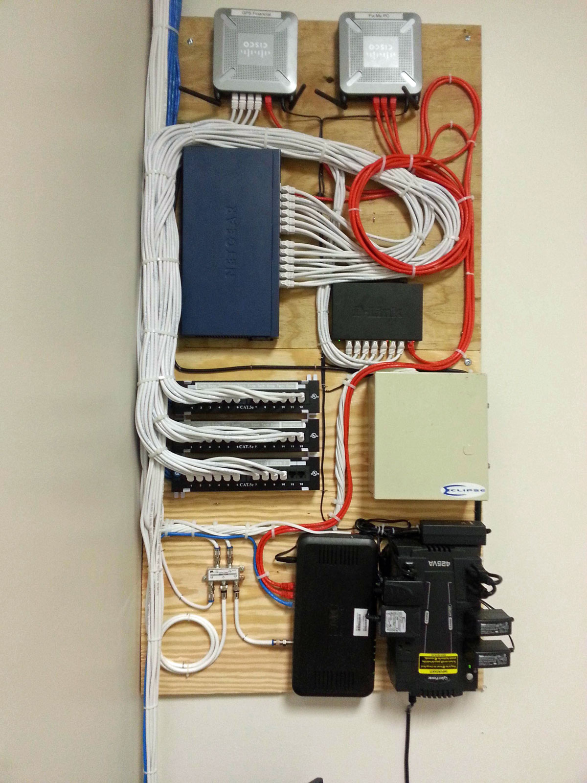
Doing neat work is the best way to keep things in order. Notice all the wires are labeled. All the ground conductors have heat shrink, which is required on insulation displacement terminations like 66 blocks, 110 blocks, and ICON terminations.
ADC ICON termination block
Once all the work is done, the wire run sheets are updated with changes and additions (there are always changes and additions) which will keep the documentation accurate.
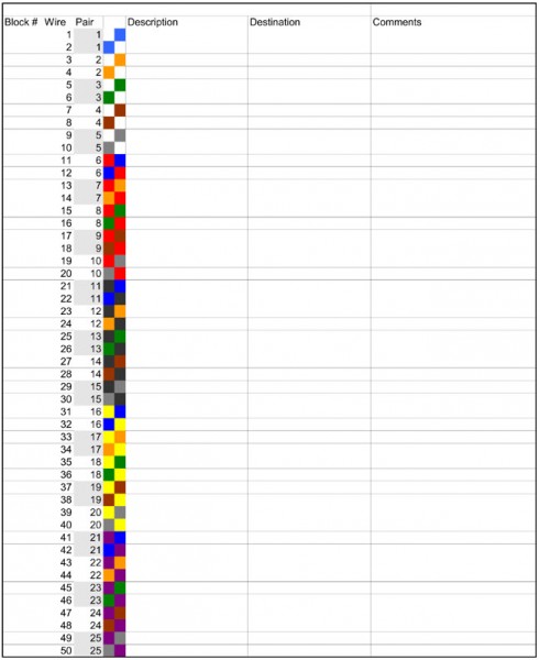
I made up several templates with the wire color code, pair number, and cable information on each wire. This allows the wire man to quickly enter changes to the wire information on the sheet. At the end of the wiring project, these forms can be saved in several places, printed out, and placed in a book or however, the engineering manager wants to keep the information.
For 16/24 pair Gepco cable on ADC ICON Termination blocks, click here.
I say Gepco cable, any audio cable that is color coded with standard resistor color codes will work with these sheets, or the sheets can be adapted for use with other cables.
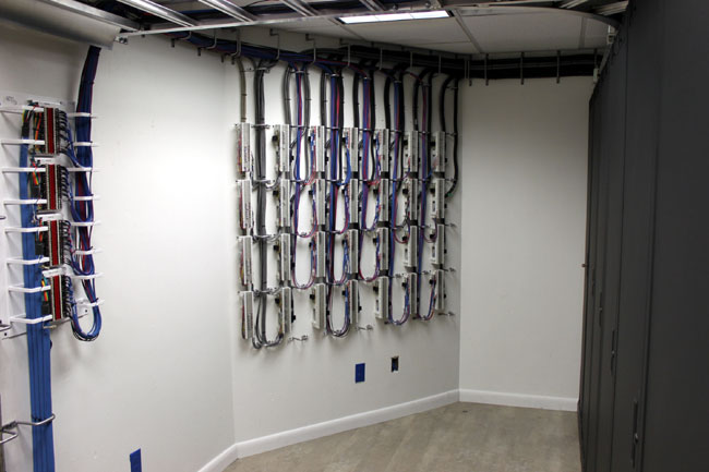
66 blocks audio and control for nextgen installation
This is a good installation. The company I work for has several wiremen that are artists and do excellent work. Notice there is adequate room and light to work on the wall. A dark, cramped area will lead to hurried work, poor workmanship, and mistakes in wiring.
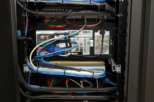
Automation computer on slide-out rack with cable management system
All the cables to the rack mount computers are neatly dressed, which allows easier service.
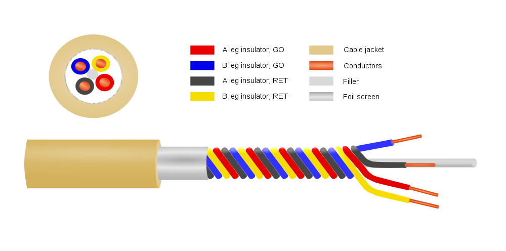
Or Star Quad Microphone Cable, depending on who is making it.
Star Quad Microphone Cable Diagram
This has been around for quite a while, but many studio/broadcast engineers don’t understand it or don’t use it for some reason. Microphones and mic pickups produce relatively low signals when compared to line-level audio. Most microphone preamps have a gain of +50 dB, which means any noise gets amplified and even small things can become major problems quickly.
Gepco MP1201 Quadstar Microphone Cable
Under general conditions, most balanced shield twisted pair (STP) audio cable such as the standard Belden 8450 is adequate for stationary microphone cable for short runs. When the cable is not permanently fixed in place, as in hand-held microphones, microphones mounted on booms, or other nonfixed microphone applications, then a flexible cable must be used. Star Quad cable has better noise specifications than standard flexible microphone cable.
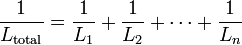
The advantage of Star Quad cable for low-impedance microphones (150 ohms) is that the parallel twisted pairs significantly reduce inductive reactance. In AC circuits, inductive reactance acts as a low pass filter, gradually rolling off as the frequency is increased. This effect is cumulative, the longer the cable run, the more inductive reactance is added to the circuit. The result is microphone audio can have smeared or ill defined high frequency audio.
parallel inductance formula
Using two parallel twisted pairs is similar to parallel resistors when it dealing with inductive reactance, it halves the value.
In addition to reducing inductive reactance, the tighter twist found in Star Quad cables reduces the CMRR by about 20 dB. The Star-Quad configuration keeps the conductors in the same relative position to each other as the cable is flexed and moved around. All of this makes it superior to standard STP microphone cable.
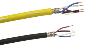
Several companies manufacture Quad Star cables:
Belden: 1192A
Canare: L-4E6S
Gepco: MP1201
Mogami W2534
Cardas 4X24
The price of Star Quad cables runs about 40-60 cents per foot (more for the Belden, much more for Cardas) if purchased in bulk. That is about the same range for two conductor mic cables.
As good as this cable is, I don’t think they had this in mind when they made it:
I wonder what the centripetal force on that cable is when the microphone is in full motion. Also, I’d bet that SM58 was none the worse for were after it’s crowd surfing moment.