Radio stations more and more revolve around networked computers. Engineers need to understand computer networking, especially as it relates to audio distribution and playback. Eventually, I see broadcast engineers being more computer science types rather than electrical engineering majors.
What I have found out about computer networking is this: it is not rocket science. In fact, most of it is pretty easy. Physical networking and cabling are similar to audio and TELOC cabling. Automation computer servers themselves are not difficult to understand as most of them run on some type of Windows program. Other servers such as Apache for WWW and for FTP and streaming run on some type of LINUX OS. LINUX is also not difficult to understand so long as one knows the right command line prompts.
The first part of understanding computers is networking. Without a computer network, a computer is a glorified typewriter. Almost every automation system and or digital editor requires some type of network. Consoles and computers that use AOIP require well-constructed networks in order to operate properly. To that end; cabling choices, network interface devices such as switches and routers, patch panels, and so forth need to be specified and installed with care.
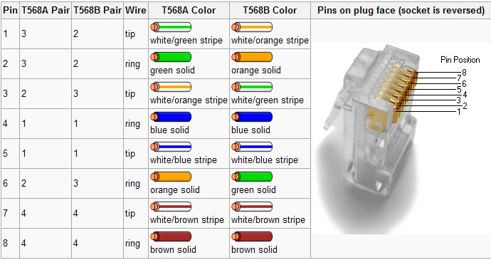
Most often, it is the simple things that will trip an installer up. The one area where I have found the most mistakes made is the pair’s connection to various termination points. There are two basic standards, TIA/EIA T568A and T568B. Neither is better than the other, both are often identified on terminating devices such as jacks and patch panels. The most important aspect of these standards for an installer is to pick one and stick with it.
TIA/EIA 568 color code
When certifying networks, the most common problem I have encountered is crossed pairs. Almost invariably, one end will be punched down with the A standard and the other with the B standard. Jacks are particularly difficult, as the color-coding stickers show both. Many patch panels have a slide-out, reversible card with is an either/or situation. For some reason, I have stuck with the B standard, and on any project I am managing, I get rid of all the A color codes I can find and tell the installers that B is the only acceptable termination standard. That cuts down on a lot of errors and redos during certification. That is good, it saves time and I hate redos.
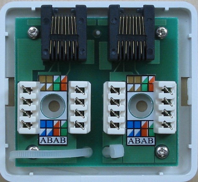
Cat 5e wall jack set
You can see that this color code marking can lead to confusion. I take a sharpie and cross out all the A markings to avoid installation mistakes.
Incidentally, on any new network installation, Category 6 cable should be used. As more and more data throughput is required for network applications, Category 6 Cabling has better performance specs and will likely have a longer service life than another cable. It may be a little bit more expensive than Cat 5, however, well worth the investment. It would be a great mistake and a waste of money to have to pull out the network and reinstall it in a few years because the cabling doesn’t have the required bandwidth.
I love wire. I know, what a geeky thing to say, but it is true. For no reason that I can explain, I have always been fascinated with wire, cables, and electricity.
Category 5e and up cabling is amazing stuff. Designed for computer applications, it can fulfill a wide variety of roles in radio and television stations, mostly because of its high bandwidth capacity. Category 5e cabling has a 100 MHz bandwidth, category 6 bandwidth is 250 MHz, with 6a (augmented) being 500 MHz. AES/EBU audio uses ATM and requires from 4-26 MHz bandwidth, depending on the sample rate (the highest sample rate is 200 KHz). Category 5e cable has a minimum common mode balance of -60 dB, which makes it nearly impervious to RF, electrical noise, mutual interference, and other noise issues.
Further, each pair in category 5e or 6 cables has a different twist rate, to reduce cross-coupling between pairs.
Here is a chart of electrical characteristics for Cat 5e, Cat6, and Belden AES/EBU cable:
Category 5e
Category 6
AES/EBU*
Impedance (ohms)
100 +/- 10%
100 +/- 10%
110 +/- 20%
Bandwidth (MHz)
100
250
52
DC resistance 1K Ft (ohms)
27.12
27.42
23.68
Capacitance per Ft (pF)
15
15
12
Velocity factor (%)
72
72
76
Common Mode Balance (dB)
60
63
30
NEXT
-44.3
-53.4
–
Configuration
UTP
UTP
SPT
Wire
Solid
Solid
Stranded
Gauge
24
23
24
* Belden 1800F
Specifications above are for Belden cabling, but are typical for high quality category cabling available from other sources as well.
Although the AES/EBU cable specifications call for 110 ohm impedance cable, that specification is pretty loose, calling for +/- 20%, which means 88 to 132 ohm cable will work well. Category 5e and 6 cable is 100 ohm impedance, +/- 10%, which translates to 90 to 110 ohms, nominal.
Category 5 and 6 cabling can also be used for analog audio, RS232 and RS485 applications. One area of caution, however, is for T-1 or fractional T-1 services. On the DS side (between the smart jack and the CSU), T-1 type service runs 3 volts peak to peak. That is much higher than AES/EBU or ethernet, which run 1 volt peak to peak. As a result, cables in this type application should be 22 gauge or higher to reduce emissions from the cable.
Shielded category cable is available in Cat5 and 5e. The shielding acts to reduce emissions from the cable in low noise environments. It can also act to reduce RF fields around the cable pairs, so long as the proper cable terminations for shielded cable (RJ-45 or more properly 8P2C connectors) are used and installed correctly. The shield must be connected to a ground on at least one end. I know a facility that has all shielded Cat5 cable, but they used standard RJ-45 connectors, so both ends of the shield are floating, which completely defeats the purpose of the shield.
25 pair category 5e cable is available for trunk cabling between studios and the technical operations center. For one studio project, I purchased pre-made cables with RJ-21 connectors on both ends. Those connectors were then plugged into KRONE LSA-PLUS blocks. Cable, connectors and blocks were all 100 ohm impedance, category 5 equipment. Since we did not have to strip any insulation or punch down any wires, we pulled and terminated the studio to rack room trunk cables for five air studios and three production rooms in one morning. This greatly sped up the studio build out process.
The studios and TOC use SAS 32KD (Sierra Audio Systems) audio routers and Rubicon SL consoles, so most of the audio is AES/EBU. There are, however, several analog audio sources that are included in this system, things like telephone caller audio, off air monitors, satellite feeds and remote broadcast sources.
This facility is located about 1 mile away from a 5 KW AM station on 850 KHz. Several concerned people commented on the possibility of RFI on the cabling. In the five years since that project was completed, there have been zero issues with the cabling or the audio quality.
One thing to consider in these installations is the length of the cabling and the sample rate being used across the network. The capacitance per foot is the deciding quality in cable lengths. This is because capacitance, which is the ability to store an electrical charge, will begin to distort the signal (turn it into a saw tooth waveform) in the cable if certain lengths are exceeded. A good way to calculate maximum cable runs is thus:
Most professional AES/EBU devices sample 24 bits per channel, if the sample rate is 48 KHz, the 24 bits x 48,000 Hz = 1,152,000 bits per second per channel. For stereo, as most applications will be, that is doubled to 2,304,000 bits per second, or 2.3 Mbps. There is some overhead in an AES/EBU signal, so, for arguments sake, we will call it 4 MHz.
In this facility, the sample rate is locked at 48 kHz by a master clock. The longest cable length is 145 feet, which adds (15 pF x 145 Ft) up to 2,175 pF capacitance. From the chart above, we know that Cat5e has a resistance of 27.42 ohms per 1000 feet, or 0.02742 ohms per foot. That works out to be 145 feet x 0.02742 ohms = 3.9759 ohms.
To calculate the capacitive reactance, the following formula is used:
Xc= -1/(2π FC)
Where Xc is the capacitive reactance, F is the frequency in Hz and C is the capacitance in Farads.
Therefore Xc = -1 / (2 x 3.1415 x 4,000,000 x 0.000000002) = -19.89 ohms.
The characteristic impedance of Cat5e and Cat6 is 100 ohms. The DC resistance is 3.97 ohms and the capacitive reactance is -19.89 ohms, make the circuit impedance of a properly terminated cable 145 foot cable 84.08 ohms.
The design formula for a low pass filter is thus:
fc = 1/(2πRC)
Where fc is the cutoff frequency, R is the resistance and C is the capacitance.
Therefore, fc= 1/(2 x 3.1415 x 3.9759 ohms x 0.000000002 farads) = 20,014,958 Hz or 20 MHz.
Generally speaking, one should try to keep the capacitance below 2500 pF in a 10 Mbps circuit. Belden datatwist 1212 cable has a 4.0 dB insertion loss and a 23.0 dB return loss per 100 meters (328 feet) at 4 Mhz.
145 feet is well within the limits of this cable for AES/EBU applications.
Further, all cable circuits need to be properly terminated to reduce return loss. Using common impedance wiring blocks, connectors and terminations help keep return loss to a minimum. Stranded wire works better in applications where cabling may move. There are Cat5e and Cat6 stranded cables available.
As data transfer rates approach that of RF, ethernet, digital audio, and RF are going to seem more and more similar. 1000 Base T (1GBT) and 10000 Base T (10 GBT) networks are coming.
Radio studios involve quite a bit of wiring. Runs between the console and equipment are pretty straightforward, from whatever the connector required for the equipment to whatever the connector required for the console. When it comes to trunk runs between the rack room and the studio, however, some type of terminating block is required.
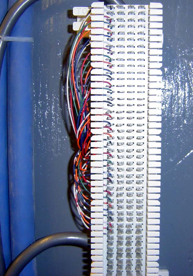
66 block or M block insulation displacement wire termination
This particular cabling installation is for low-level signaling, contact closures, and the like. It uses a Belden cable with 37 un-twisted wires which do not follow the standard Western Electric color code. The color code can be found here. If it were audio or data, the wires would be terminated differently. That color code can be found here. For more information on color codes and pinouts, see this post.
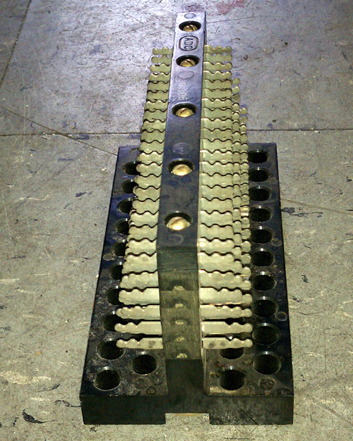
Many engineers use the venerable 66 block or M blockinsulation displacement termination. These terminal blocks were designed by ATT to terminate 25 pair 22 through 26 gauge solid wire. The original design was rated for category 3 (16 MHz or 10 mb/s) communications standards. Newer designs are category 5 or 5e compliant (350 MHz or 100 mb/s). Notice the part about the solid wire. Most audio wire is stranded and as such, the metal fingers on a 66 block will cause stranded wire to spread out losing contact with the terminating finger. This causes intermittent connections and audio dropouts, which I have experienced often (before I knew better, I used 66 blocks when building studios). The way to cure audio dropouts on a 66 block is to heat the termination fingers with a soldering iron. This melts the wire insulation and gets it out of the way. In the long run, it is better to use more suitable terminations.
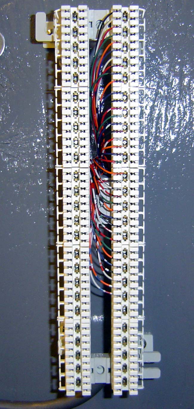
Krone LSA-PLUS 110 type wire termination block
The 110 block is an updated version of the punch block for high-speed networks. it is also designed for 22 through 26 gauge solid wire. This is the termination used on category 5, 5e, 6 patch panels and RJ-45 jacks. They are also formed into block-type terminations the size of small 66 blocks. The 110 block is designed for 500 MHz (1 gb/s) or greater bandwidth. Krone makes a version of a 110 block called LSA-PLUS which is an acronym that stands for: Lötfrei, Schraubfrei, Abisolierfrei, Preiswert, Leicht zu handhaben, Universell anwendbar, Sicher und schnell. This translates to: no solder, no use of screws, no insulation removal, cost-effective, easy to use, universal application, secure and fast. Unlike a standard 110 block, the Krone block is designed for solid or stranded wire. 110 blocks are acceptable for use with AES/EBU digital audio at sample rates greater than 268 KHz as well as gigabit networks and analog audio.
In very old installations, I have seen Christmas trees. This is a wire wrap system where wires are wrapped around metal fingers that form the shape of a pine tree, hence the name. They were very popular in the fifties and sixties and only work with solid wire. It is also time-consuming work and requires special tools and skills. Wire wrapping is a bit of a lost art.
Christmas Tree wire wrap termination block
Screw barrier strips have been used to terminate audio cables from time to time. I wouldn’t consider this method because it is too time-consuming, takes up too much space, and is difficult to label.
ADC ICON wire termination block
ADC makes a good termination block called ICON (Integrated Cable Organization Network) which uses QCP (Quick Connect Panel) connectors. the connectors are small square devices that are insulation displacement termination (like 66 and 110 blocks) but require a special tool to “punch down.” This particular type of connector is well suited for stranded wire from 22 through 26 AWG. QCP connectors are also used on some of ADC’s patch panels and other audio products. Like any other termination technology, they are only as good as the person punching down the wires. QCP connections are small high-density devices, I have seen them get mangled by someone in a hurry who got his punch-down tool across two of the terminals by accident. ICON blocks can be used for digital audio, however, they do not maintain the 110 ohms impedance of most digital-type audio cables (neither do XLR connectors, by the way). This can lead to some return loss, which on longer cable runs can cause problems.
Radio Systems Studio Hub wiring diagram
Radio systems prefer RJ-45 connectors with Category 5 cable, something they call Studio Hub. These are 110 blocks as noted above, but designed primarily for computer networks. Radio Systems discovered that the impedance of most audio cables is very close to that of computer network cables, audio cable is designed for 110-ohm impedance vs. computer network cable which is designed for 100-ohm impedance. Therefore, RJ-45 connectors and shielded or unshielded twisted pair work well with balanced professional audio, either analog or digital.
For analog audio wires, ICON blocks seem to be the best, most secure high-density termination system. In all my years of using them, I have never had a connection go bad. 110 block and other category 5 or 5e systems also work well. For digital audio, Krone blocks or 110 blocks need to be used in order to maintain the full bandwidth characteristics of the cable being used. Using appropriate cable and or terminations in digital audio circuits often leads to impedance mismatches and high return losses in the system.