The Isolated Ground

We get requests to install Isolated Ground outlets from time to time, especially with sensitive equipment. TELCO likes to have isolated grounds on their fiber MUX’s.  It can become an issue with branch circuits in split-phase or three-phase services that share the same ground and neutral conductor.  This can lead to a ground loop between neutral and ground, which will create all sorts of havoc in a broadcast facility.

20 amp, 120 volt Isolated Ground Outlet
20 amp, 120 volt, Isolated Ground Outlet

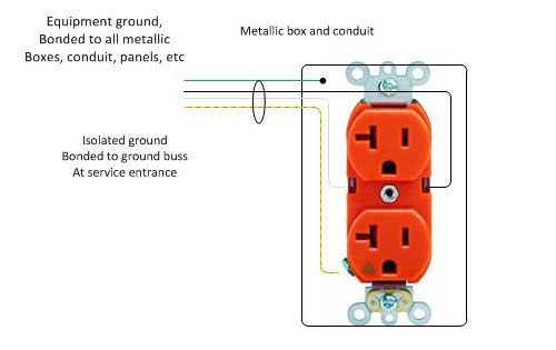
The National Electrical Code covers Isolated Grounds (IG) and sensitive equipment in several sections.  The first is section 250.146(D), which states that the installation of isolated ground receptacles is permitted.   The grounding conductor connected to such receptacles is permitted to pass through one or more panel boards, boxes, conduit bodies, etc without being bonded to them.  However, said panel boards, metallic boxes, conduit bodies, raceway, etc must also be grounded separately.  That means running two ground conductors, usually, the isolated ground conductor is green with a yellow stripe or spiral.

Studio electrical diagram isolated ground

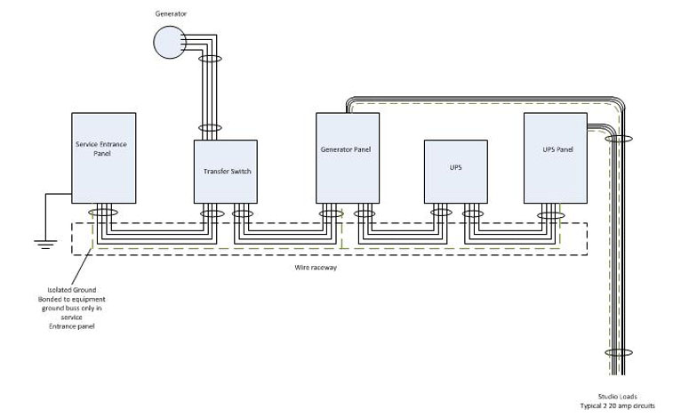
The second is section 640.9(A), which refers to separately derived power systems.  This section deals specifically with balanced power; 60 volts AC to ground.  In such cases, a separate ground conductor is allowed as outlined in section 250.146(D) and in 647.6(B), which states that the grounding buss should be connected to the grounded conductor on the line side of the separately derived systems disconnecting means.

Other sections of the NEC that may apply to broadcast radio and television facilities:

  • Article 455, Phase converters (rotary phase converters)
  • Article 480, Storage batteries (UPS)
  • Article 520, Theaters, Audience Areas of Motion picture and Television studios, Performance areas, and similar locations
  • Article 640, Audio signal processing, Amplification and Reproduction Equipment (Audio wiring)
  • Article 645, Information Technology Equipment (computer equipment and network wiring)
  • Article 647, Sensitive Electronics Equipment (balanced power 60 volts to ground)
  • Article 702, Optional Standby systems (generators)
  • Article 770, Fiber optic cables
  • Article 810, Radio and Television Equipment (antennas, towers, and grounding)
  • Article 820, Cable TV (CATV)
  • Article 830, Network-powered broadband communications systems (power over ethernet)

If interested, I can do articles on these sections as well.

Conduit fill

It may be surprising to some, but the number of wires allowed in any given conduit is not “as many as can be jammed in there.” The National Electrical Code, AKA NEC or NFPA 70 gives specific guidance on the number of current-carrying conductors allowed in any specific size and type of conduit.

This is due to the fact that current-carrying conductors generate heat.  Cables enclosed in a conduit need to dissipate that heat so that the insulation on the cable doesn’t melt, which would be a bad outcome.

Conduit fill tables are found in Chapter 9 of the NEC.  There are several tables that give the number of conductors for each size and type of conduit.  Then there is the general rule of thumb that for more than two cables, the maximum conduit fill is 40%.  This comes in handy when several different size conductors are being run in the same conduit.

An example of this is when several circuits are going across the room to the same general location, in this case, a row of transmitters and racks.  Instead of running individual conduits for all those units, one or two conduits from the electrical panel are run to a square wireway, then the individual circuits are broken out and wired from wireway to the individual loads.  In this case, the following equipment is being connected:

  • Harris FM25K: 100 amp 3 phase high voltage power supply (#2 THHN), 30 amp 3 phase transmitter cabinet (#10 THHN)
  • Harris FM3.5K: 70 amp split phase (#6 THHN)
  • Harris MW1A: 30 amp split phase (#10 THHN)
  • Two equipment racks: 20 amp single phase (#12 THHN)
  • Coax switch: 15 amp single phase (#14 THHN)
  • Dummy Load: 15 amp single phase (#14 THHN)
  • Antenna switch/dissipation network for AM station: 15 amp split phase (#14 THHN)
  • Convenience outlets for the back wall: 20 amp single phase (#12 THHN)

Excluding grounding conductors, which will be addressed below, the total current carrying conductor count is thus:

  • #2 THHN: 3 each
  • #6 THHN: 3 each
  • #10 THHN: 7 each
  • #12 THHN: 6 each
  • #14 THHN: 6 each

Ampacities based on NEC table 310.16, THHN insulation in dry locations, maximum temperature rating is 90° C (194° F) based on the ambient temperature of 30° C (86° F)

Grounding conductors for each of those circuits, based on NEC Table 250.122 (all conductors are copper):

  • 100 amp circuit: #8
  • 70 amp circuit: #8
  • 30 amp circuit: #10
  • 20 amp circuit: #12
  • 15 amp circuit: #14

The final conductor count is:

  • #2 THHN: 3 each
  • #6 THHN: 3 each
  • #8 THHN: 2 each
  • #10 THHN: 9 each
  • #12 THHN: 9 each
  • #14 THHN: 9 each

The plan is to use two 1 and 1/2-inch EMT conduits between the electrical service panel and the 4 x 4 square wireway. According to  NEC Chapter 9, Table 4, the 40% cross-sectional size of this conduit is 526 mm2.  It is easier to simply use metric measurements for this.  The cross-sectional wire areas are found in Chapter 9, Table 5.  Chart of various conductor sizes and areas:

ConductorArea (mm2)Total conductorTotal area (mm2)
#2 THHN74.713224.13
#6 THHN32.71398.13
#8 THHN23.61247.22
#10 THHN13.619122.49
#12 THHN8.581977.229
#14 THHN6.258956.322

Thus, in order to break this up into two 1 and 1/2-inch conduits, the #2, #6, and #8 (main transmitter HV power supply, backup transmitter, and grounds) are run in one conduit, the remaining circuits in the other.  The idea is that the main transmitter and backup transmitter will not be running simultaneously for long periods of time.  Those cable areas total 369.48 mm2, well within the 40% limit of 526 mm2 for 1 and 1/2 inch EMT.   The rest of the circuit’s cable areas total 256.041 mm2.  That leaves room for additional circuits in the second conduit if future needs dictate.  The extra conduit area will make pulling the wires through easy.

From the square wireway to the HV power supply, 1 and 1/4 inch conduit will carry the three #2 and one #8 ground.  1 and 1/4 inch EMT has a cross sectional area of 387 mm2, the conductors contained within will be 271 mm2.  Less room here, but still well within the 40% limit.

Pictures will be posted when the project is done.