We get requests to install Isolated Ground outlets from time to time, especially with sensitive equipment. TELCO likes to have isolated grounds on their fiber MUX’s. It can become an issue with branch circuits in split-phase or three-phase services that share the same ground and neutral conductor. This can lead to a ground loop between neutral and ground, which will create all sorts of havoc in a broadcast facility.
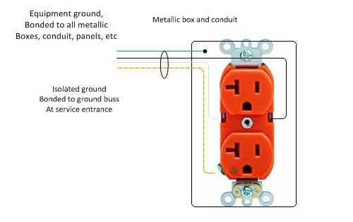
The National Electrical Code covers Isolated Grounds (IG) and sensitive equipment in several sections. The first is section 250.146(D), which states that the installation of isolated ground receptacles is permitted. The grounding conductor connected to such receptacles is permitted to pass through one or more panel boards, boxes, conduit bodies, etc without being bonded to them. However, said panel boards, metallic boxes, conduit bodies, raceway, etc must also be grounded separately. That means running two ground conductors, usually, the isolated ground conductor is green with a yellow stripe or spiral.
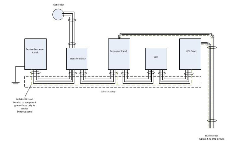
The second is section 640.9(A), which refers to separately derived power systems. This section deals specifically with balanced power; 60 volts AC to ground. In such cases, a separate ground conductor is allowed as outlined in section 250.146(D) and in 647.6(B), which states that the grounding buss should be connected to the grounded conductor on the line side of the separately derived systems disconnecting means.
Other sections of the NEC that may apply to broadcast radio and television facilities:
- Article 455, Phase converters (rotary phase converters)
- Article 480, Storage batteries (UPS)
- Article 520, Theaters, Audience Areas of Motion picture and Television studios, Performance areas, and similar locations
- Article 640, Audio signal processing, Amplification and Reproduction Equipment (Audio wiring)
- Article 645, Information Technology Equipment (computer equipment and network wiring)
- Article 647, Sensitive Electronics Equipment (balanced power 60 volts to ground)
- Article 702, Optional Standby systems (generators)
- Article 770, Fiber optic cables
- Article 810, Radio and Television Equipment (antennas, towers, and grounding)
- Article 820, Cable TV (CATV)
- Article 830, Network-powered broadband communications systems (power over ethernet)
If interested, I can do articles on these sections as well.

Nice to see this being addressed… the facility where I cut my radio teeth many years ago is still fighting with grounding issues, among others. I’d be interested to see an article on NEC Article 810… it’s got my vote.
Thanks for the post!
My employer is about 1 mile from two 50kw non-directionals which are themselves
less than a mile apart. They differ by 60 khz. We recently added 5 more production
counting inputs into an existing system, everything was wired in a “star” configuration,
with the hub being the connection the data network.
On the large/high speed machines. there are also 2 annunciator lights that work
in conjunction with counts of products into the “box” at the end of the line.
When the oldest and “best-grounded” machine was added, its wire run just happened to collect
all that rf ground current. When the system tried to turn on the output for the “red”
light, the opto-22 output module saw all this modulated 60khz rf, and not only did the light
modulate with the sum of the modulation products, it also completley befuddled
the opto 22 INPUTS’ ability to see the count pulses cleanly. The calculated speeds of several machine varied wildly. I tried chokes, filters, ferrites, etc.
It did require the installation of a physical relay to keep the 60 khz off that line.
The “computer” people at my employer and the company which makes the “auto-count” system had no idea what was to be done, except that they were sure not going to accept responsibility for having created the problem, or not having included any rf filtering in their design.
If they had taken a litle more interest in the problem, I would have shared the solution with them. I wonder if I’m being too harsh, but I’m beginning to become cranky
about “computer people” who somehow think it’s OK to be ignorant about rf or other “noise” issues.
Not necessarily related to isolated grounds, but back in the 80s I worked for a company that was installing a small computer room in an old industrial building with 3-phase Wye service. They wanted three separate circuits, because of the current draw. One circuit ended up operating a small A/C unit just for the room (about 12×12). So the electrician ran four wires to the room: three individual hot circuits (one from each phase) and one neutral, and wired the room up. The room was about 100 ft from the distribution panel. It didn’t take more than a few months for equipment to start failing. When we measured the AC voltage, we found that when the A/C came on, it pulled the neutral down, reducing the voltage on that outlet to 100V. By unbalancing the neutral, the voltages on the other outlets rose to 140V and the equipment attached to them became quite unhappy. The only “cure” was to run two brand new neutrals to the remaining outlets.
Apparently sharing a neutral is quite common but it also brings in some problems. If you specify separate circuits, make sure the electrician knows that means separate neutrals as well.
I’ve been doing a lot of work in a facility that has these installed for almost EVERYTHING. While they seem like a good idea, I’m not 100% convinced they aren’t causing more problems then they are fixing. I usually try for the everything bonded to everything style of grounding (certain exclusions may apply). Where do you use isolated grounds when following the somewhat vague “good engineering practices”? How bad of an idea is it to “mess them up” with additional grounding?
I’ve read that many IT data center designers are abandoning iso grounds because they introduce more problems than they prevent.
It is becoming clear that sometimes even the designer does not/can not anticipate
all the possibilities of any particular installation.
Sometimes what is right is wrong and the “wrong” end of a shieled cable must be grounded.
Sometimes both ends must be grounded and this is textbook wrong but sometimes the only solution. There are cases in low level wiring where I’ve had to let the ground float
at both ends, but rf bypass at one or both ends.
If you can throw a scope on the various grounds, you can see where noise is coming back from. The problem with more problems being caused than solved is simply the nature
of modern engineering to refuse to admit that things they all agree on, like switching power supplies are large part of the collective problem isolated grounds attempts to address.