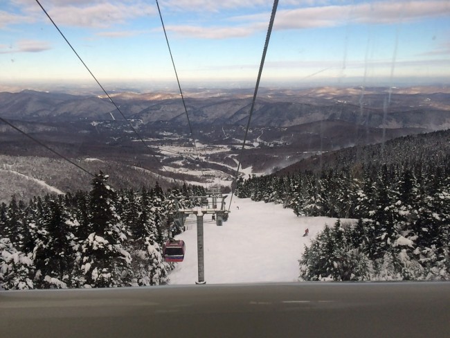
What better time to take the gondola to K-1? None, none at all. We do work for the two radio stations that are on the peak of Mount Killington, near Rutland, Vermont. In the summer, usually, we can drive up there in a four-wheel drive truck. In the winter, the gondola is the way to go. On this day, there was a 48-56 inch base, light north winds, and air temperature around 10° F (-12° C) .
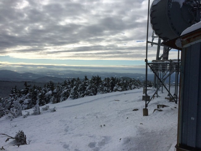
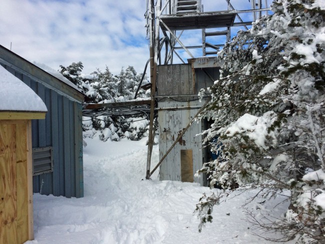
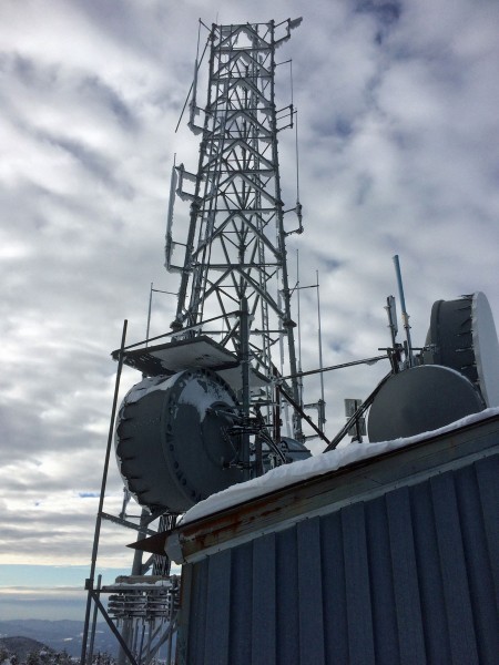
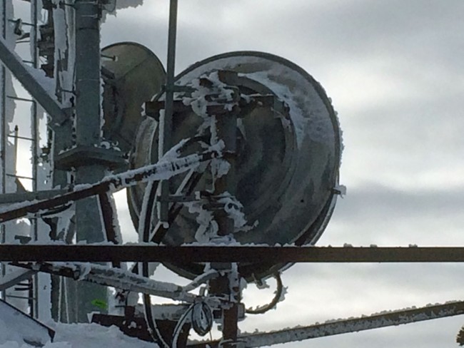
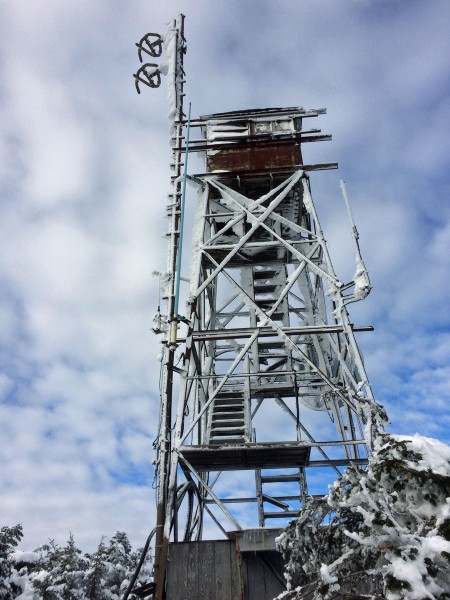
Ride up to Killington PeakView from Killington PeakTransmitter buildings on Killington PeakView from Killington PeakTower from Killington PeakKillington STL dishesERI antenna, WZRT/WJJR Killington VT
The reason for the trip today; is repair work on the Nautel VS2.5 transmitter. All three power supplies and the power supply summing board needed to be replaced.
In the progression from Circuit Switched Data to Packet Switched Data, I can think of many different applications for something like this:
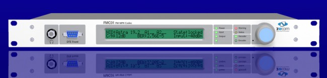
FMC01 MPX to IP CODEC
The FMC01 MPX to IP encoder can be used for multi-point distribution (multi-frequency or same-frequency network) of FM Composite audio, or as a backup solution over a LAN bridge, LAN extension, or public network. I can think of several advantages of using this for a backup when composite analog STLs are in use. There are many compelling reasons to extend the LAN to the transmitter site these days; Transmitter control and monitoring, security cameras, office phone system extensions, internet access, backup audio, etc. I would think, any type of critical infrastructure (e.g. STL) over a wireless IP LAN extension should be over a licensed system. In the United States, the 3.6 GHz WLAN (802.11y) requires coordination and licensing, however, the way the rules are set up, the licensing process is greatly simplified over FCC Part 74 or 101 applications.
Another similar CODEC is the Sigmacom Broadcast EtherMPX.
Sigmacom Broadcast EtherMPX CODEC
Features include: • Transparent Analog or Digital MPX (MPX over AES), or two discrete L/R channels (analog or AES). • Built-in MPX SFN support with PTP sync (up to 6.000km in the basic version). No GPS receivers! • Unicast or Multicast operation to feed an unlimited number of FM transmitters with MPX from one encoder. • Linear uncompressed PCM 24-bit audio. • Very low audio latency: 2,5mS in MPX mode. • Perfect match with Sigmacom DDS-30 Exciter with Digital MPX input. • Can be used with high-quality 802.11a/n Ethernet links. • DC coupled, balanced Analog inputs & outputs with -130dBc noise floor. • No modulation overshoots due to compression or AC capacitor coupling. • Decoder provides simultaneous Analog & Digital output for transmitter redundancy. • Aux RS232 serial transparent link, Studio to Transmitter. • Auto switchover to Analog input when Digital signal is lost. • Centralized remote control & management software
One last thought; separating the CODEC from the radio seems to be a good idea. It allows for greater flexibility and redundancy. Using an MPX-type STL allows sensitive air chain processing equipment to be installed at the studio instead of the transmitter site.
Radio Shack (AKA, RadioShack, The Shack, Tandy Corporation, Realistic, Optimus, etc) appears to be filing for Bankruptcy if the Wall Street Journal and Reuters is to be believed. I see the words “private equity firm” in the article, that does not bode well.
Radio Shack of late has become a glorified cell phone store. It used to be one could get some emergency repair parts, an FM antenna, or a CB radio as the need arose. As a young lad, it was fun to poke around and look at the various radio kits and other assorted fun things. My first shortwave radio was a kit from Radio Shack; assembly finished just in time to hear the Vatican Radio’s announcement that Pope Paul IV had died.
What happened to Radio Shack is fairly typical; what was once a niche market for hobbyists and experimenters tried to go mainstream and lost their core customers. There are still plenty of electronics hobbyists out there, look at the Amateur Radio community as an example. Yet, that market was abandoned for the more lucrative general consumer electronics market. Unfortunately, Radio Shack never produced high-quality stuff, so their reputation in the consumer electronics market was not that great. Thus, not being known for anything, they slowly slipped into irrelevance.
Remember when there was an actual competition between radio stations for the coveted #1 bragging rights? That was way back in the day when talented air persons were sought and compensated for their performances.
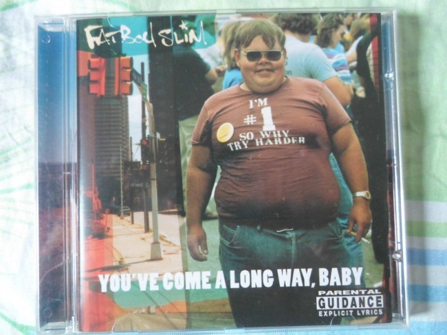
These days, when thinking about certain owners and their money men, a certain Fat Boy Slim album cover comes to mind: