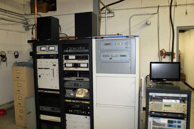
Modern Art

After replacing a burned-out FM antenna for one of our clients, the question became; what do we do with the old antenna?  There were several options:

  • Throw it behind the transmitter building and let weeds and poison ivy grow over it
  • Take it to the scrap yard to get whatever money we could for it
  • Give it away to somebody
  • Turn it into a fountain

I have scrapped these old antennas before, they are made mostly of hard yellow brass, which does not net too much at the scrap yard.  In fact, by the time I finished removing the Radomes and separating the metal, I had more time for the job than it was worth for both myself and the client.  Therefore, I present to you the ERI LPX lawn fountain:
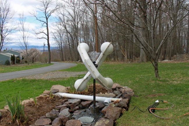
ERI LPX2E Rototiller FM antenna used as a fountain

Upon completion, my wife and daughter, who are natural-born skeptics, even had kind words to say. It seemed like a simple project at first; enlarge the dry well for the basement sump pumps and install some type of mounting base for the old antenna. It turned into a little more than that.
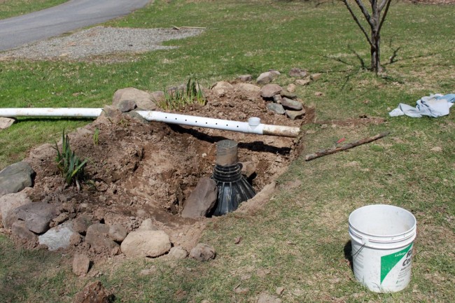
Mounting base for ERI antenna fountain

It took several hours of backbreaking labor, a concrete form, and a few bags of ready-mix concrete to create the mounting base. Several wheelbarrow loads of gravel, some rocks from the old wall in the woods, and a pond pump from the hardware store round out the installation.
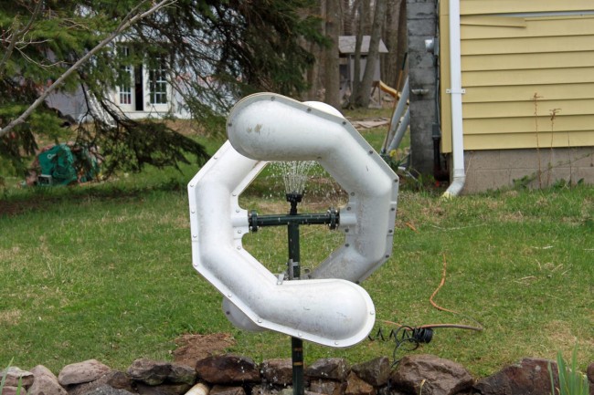
ERI LPX2E Rototiller FM antenna fountain

I am not sure what else to say.
Troubleshooting an AM array

Today, there will be a quiz.

Recently, we had an AM antenna array go out of tolerance by a good margin.  This has been repaired, however, I thought I’d post this information and see if anybody could identify the problem and the solution. Unfortunately, I don’t have prizes to give away, however, you can show off your AM engineering prowess.

All of the information is pertinent:

  1. The station has two directional arrays (DA-2) using the same towers; the nighttime array is out of tolerance, and the daytime array is not affected and is performing normally.
  2. There were no weather events connected with this event; no electrical storms, no major temperature changes, no rain events, no freezing or thawing, etc.
  3. The problem happened all at once, one day the array was performing normally, and the next day it was not.
  4. Station management reports that some listeners were complaining that they could no longer hear the station.
  5. The ATUs and phasor were inspected; all RF contactors were in the proper position, no damaged or burned finger stock and no evidence of damaged components (inductors or capacitors) was observed.  Several mouse nests were cleaned out of the ATUs, however, this did not change the out-of-tolerance antenna readings.
  6. The towers are 1/4 wave (90 electrical degrees) tall.

Readings:

TowerPhase angle as licensedCurrent ratio as licensedPhase angle as readCurrent ratio as read
1147.20.583149.50.396
2 (reference)01.0001.00
3-1370.493-125.80.798
4107.50.48192.70.355
5-38.10.737-60.20.623
6-178.70.382142.80.305

Licensed values for common point current is 13 amps, impedance is 50 ohms j0 and there is normally no reflected power on the transmitter.  On this day, the common point current readings were 8.9 amps, impedance 38.5 ohms +j5 the transmitter had 340 watts of reflected power.

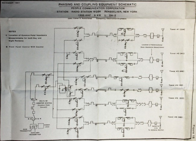
This is the overall schematic of the phasor and ATU:

WDGJ overall RF schematic diagram
WGDJ overall RF schematic diagram, click for higher resolution

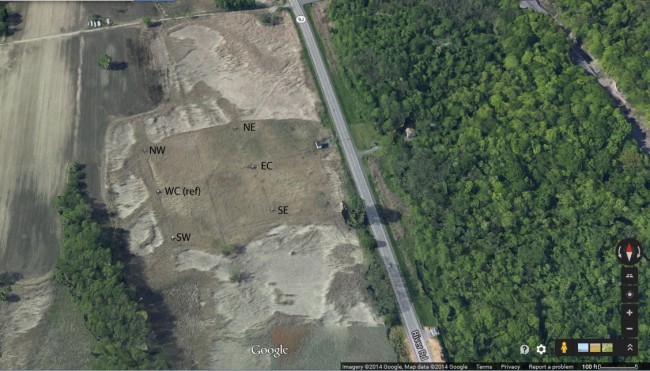
Aerial view of the transmitter site, oriented north:

WGDJ aerial view showing towers as identified in schematic diagram
WGDJ aerial view showing towers as identified in the schematic diagram

So, where would you begin?  Ask questions in the comments section.

WMHT’s former analog transmitter

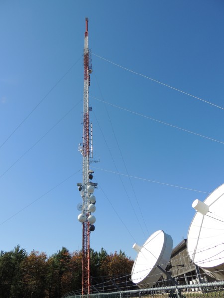
During the digital TV conversion in the US, all broadcast television stations installed new transmitting equipment and antennas.  Most stations ended up on a different frequency than their original analog channel.  In Albany, New York, all of the TV stations moved to a common transmitter site and installed their antennas on a single tower.

home of WRGB, WTEN, WNYT, WXXA, WMHT, and WCWN
Albany DTV tower, home of WRGB, WTEN, WNYT, WXXA, WMHT, and WCWN

For more on the Albany DTV site, check out the NECRAT page: www.necrat.us/albdtv.html

So, what happened to the old Analog TV sites in Albany?

For the most part, after the analog turn-off on June 12, 2009, the sites have sat empty.  Such is the case with the former WMHT site.

Sign outside of former WMHT transmitter building

This old sign about sums up the end of analog television.

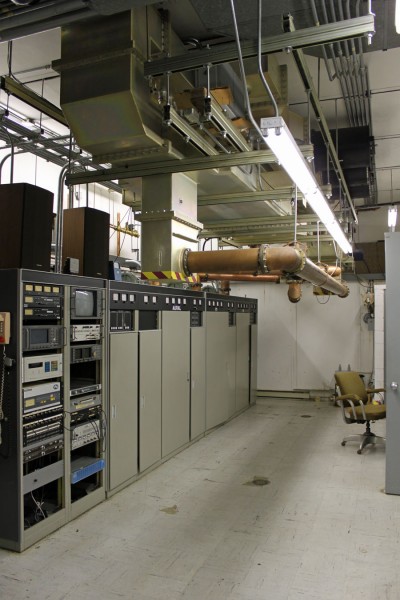
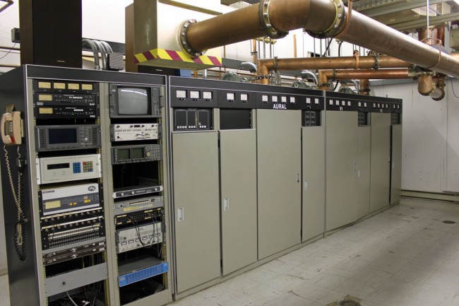
Former WMHT Comark analog transmitter
Former WMHT analog transmitter wide shot
Former WMHT operator position

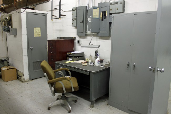
The former transmitter operator desk. The maintenance log is still open. From the looks of things, they opened the circuit breakers and walked away. Everything remains intact from the antenna to the klystrons and exciters. It does appear that the coolant has been drained from the system. Other than that, it seems like the whole thing could be restarted with minimal effort.

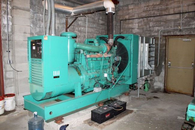
Former WMHT Onan DFN 350 backup generator

There were two Onan DFN 350 backup generators. With a TV transmitter, running the cooling system after shutdown is vital. The idea here is that both generators in parallel could run the whole station, if one generator failed, then the cooling system would still run and cool the klystrons.

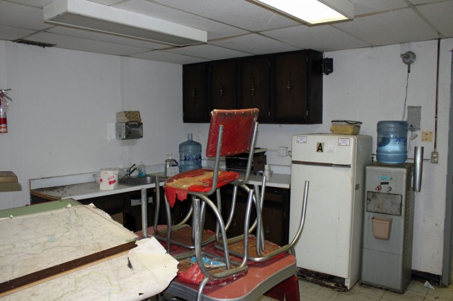
Former WMHT site kitchen
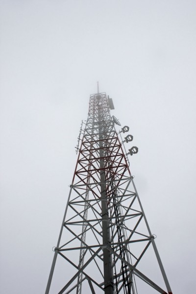
Former WMHT tower, wave guide and WVCR antenna
Former WMHT tower, waveguide and WVCR antenna

The former WMHT tower, which currently holds the WVCR-FM, WXL-34 (NOAA weather radio), and W44CT-D (Three Angles Broadcasting) Low power TV transmitter.

Current site occupants; WVCR-FM and W44CT-D

These equipment racks and the NOAA weather radio transmitter in the other room are the only active equipment at this site.

WMHT-TV Chanel 17 (488-494 MHz) was signed on 1962 from this site.  The Comark transmitter was installed in 1984.  The station’s analog ERP was 2000 KW visual, 200 KW aural.

It is an interesting site.