There are many times when some mathematics is needed in this profession. For one-off situations, the calculator applications found on most smartphones will work just fine. However, sometimes the calculation is complex or is needed to be repeated many times. Excel Spreadsheets have many mathematical functions built in. Plugging a formula into an Excel spreadsheet is a handy tool.
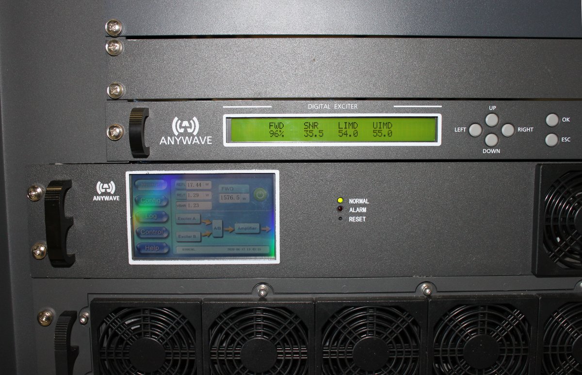
I recently acquired this rather nice precision power meter:
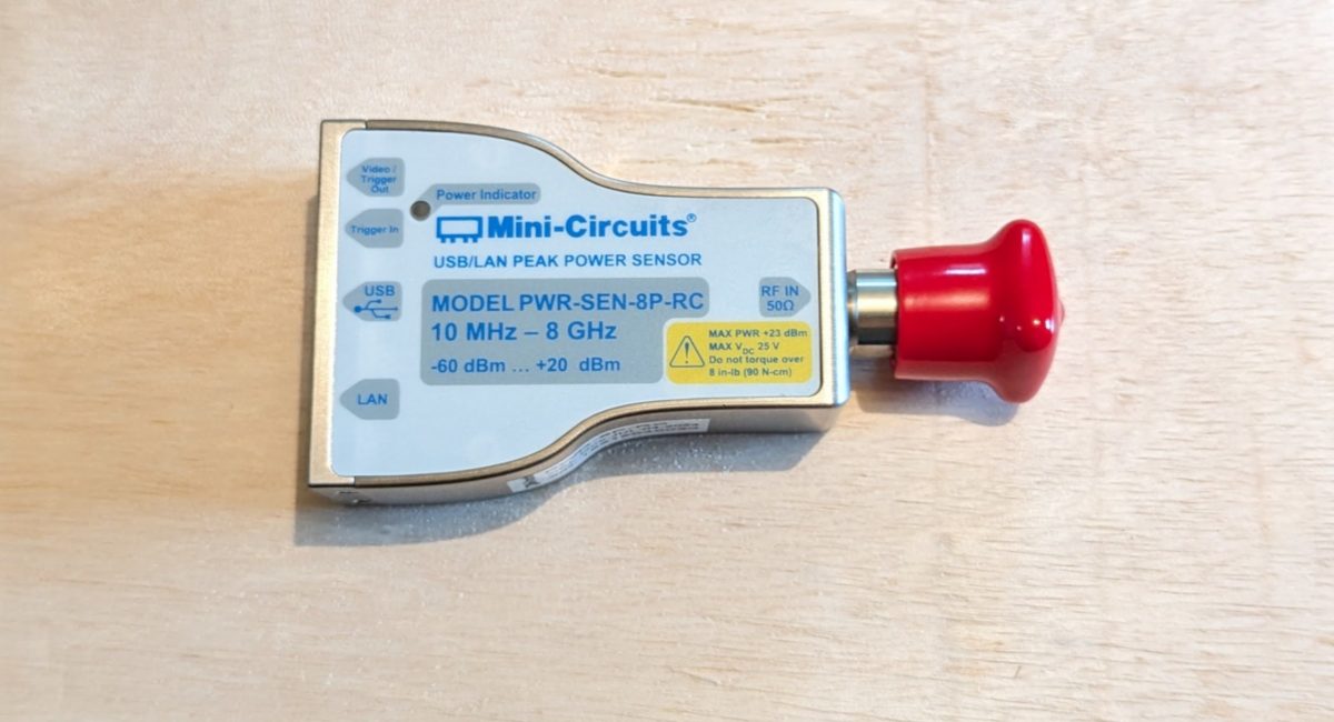
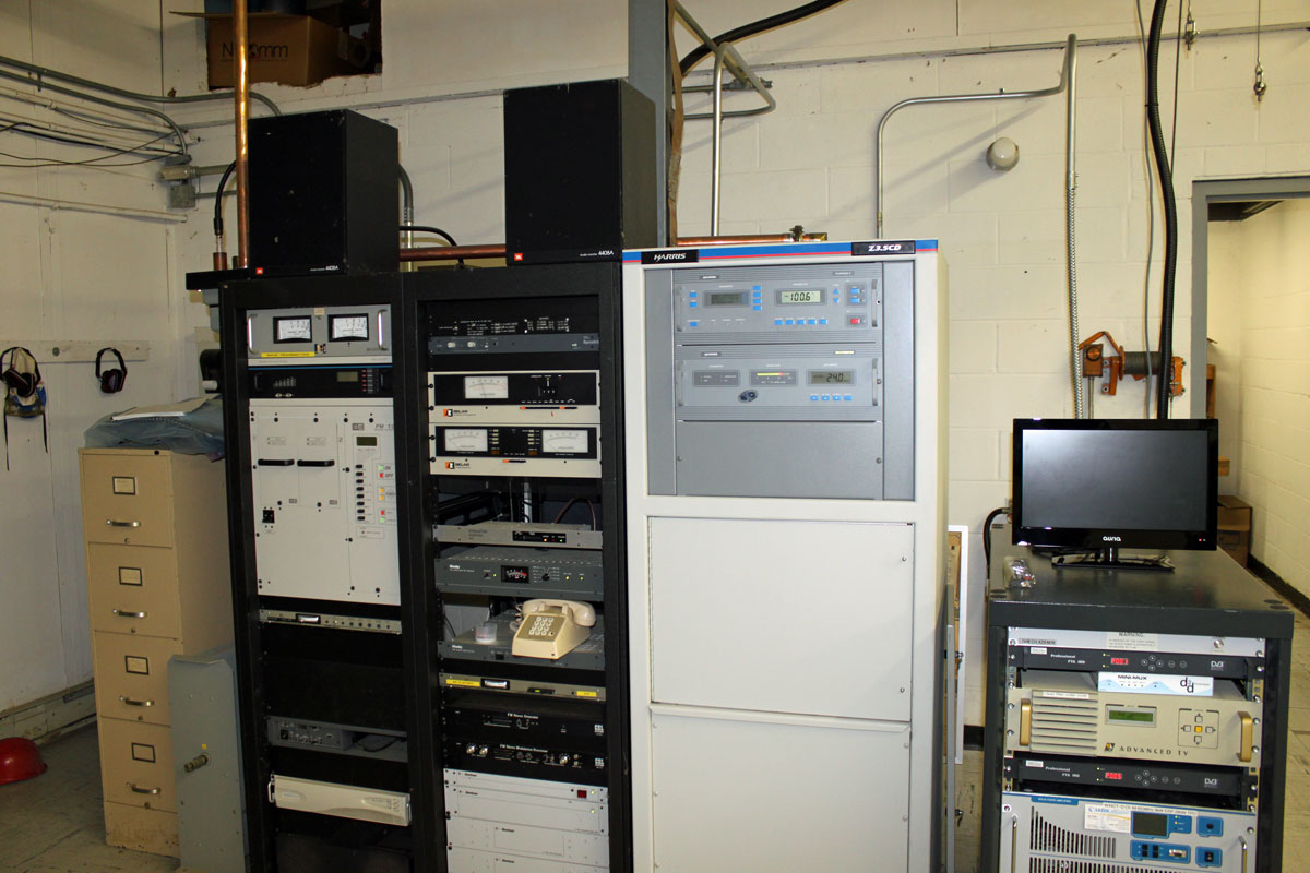
It has an input power range of -60 to +20 dBm with a stern warning not to exceed +23 dBm. Since we will be using this for a variety of applications, I thought it might be useful to know approximately how much power will be presented to the instrument in any given situation. For example, we are installing a 30 KW FM transmitter soon. The directional coupler that will be used has a coupling factor of -48.5 dBm. The TPO is 28,000 watts.
The formula to convert Watts to dBm is dBm=10 X Log10(Pw) + 30, where Pw is power in Watts. Thus dBm=10 X log10(28000) + 30 or 74.4715 dBm minus the 48.5 dBm coupling factor which is 25.9715 dBm. That is too much input for this power meter. A 20 dB attenuator will need to be used.
Since I will be using this meter in other places, rather than doing that calculation over and over again, why not build an Excel spreadsheet? That would make it easy to check.
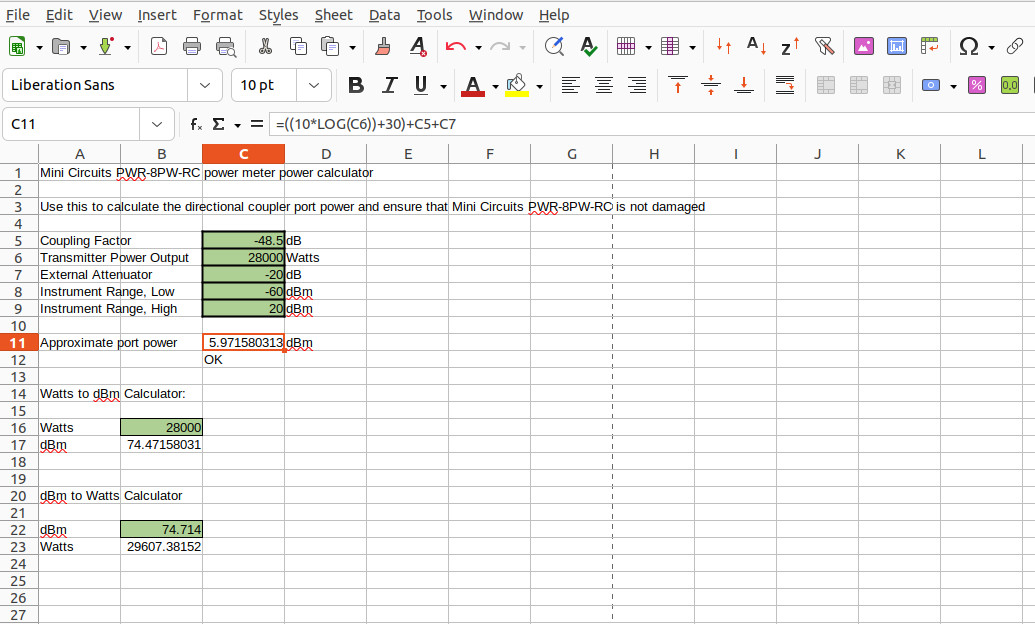
A simple Watts to dBm calculator in Excel looks like this:
=(10*LOG(C6))+30
This is copied into cell C11. C6 is the cell in which the Transmitter output power in watts is entered. The other cells contain the coupling factor (C5) and external attenuation (C7) In application, it looks something like this:
You can arrange these any way you like, just change the cell numbers to suit your needs.
I like to make the data entry cells green. You can lock the formula cells so that the formulas don’t get changed accidentally. Below the Approximate port power cell, is the IF statement that will return either a “LOW”, “HIGH”, or “OK” depending on the result value in C11. That looks like this:
=IF(C11>C9,"HIGH",IF(C11<C8,"LOW","OK"))
The spreadsheet itself is downloadable: Power meter port calculator
It would be very easy to make a system gain/loss calculator for using the licensed ERP to calculate the proper TPO.
Other examples of useful Excel spreadsheet formulas:
To convert from dBm to watts:
=10^((B22-30)/10)
B22 is the cell in which the power in dBm is entered. These can be any place you want on the spreadsheet.
Radio Frequency to Wavelength in Meters:
=299792458/B10
Where B10 is the cell in which the frequency in Hz is entered. 299792458 is the speed of light (Meters per second) in a vacuum. If you wanted the input frequency to be in kHz, simply move the decimal point for the speed of light three places to the left, e.g. 299792.458. For MHz move the decimal four places to the left, GHz five places, etc.
Convert electrical degrees to Meters:
=(299792.458/B10)/360*B11
Where B10 is the frequency in kHz and B11 is the number of electrical degrees in question.
An example of that in an Excel Spreadsheet can be downloaded: Frequency to Wavelength converter
Audio Frequency to Wavelength in Meters:
=(20.05*(273.16+B11)^0.5)/B12
Where B11 is the air temperature in degrees Celsius and B12 is the frequency in Hz. Room temperature is normally about 21 degrees Celsius (about 70 degrees Fahrenheit). Humidity and altitude can also affect the sound wave velocity, which will affect the wavelength.
Base (or common point) current calculator using base impedance and licensed power:
=SQRT(B12/B11)
Where B12 is the License power in watts and B11 is the measured base impedance of the tower (or common point impedance of the phasor).
Convert meters to feet:
=B11/0.3048
Where B11 is the length in meters
Convert feet to meters:
=B12*0.3048
Where B12 is the length in feet.
Convert degrees F to degrees C:
=(B11-32)/1.8
Where B11 is the degrees Fahrenheit
Convert degrees C to degrees F:
=(B12*1.8)+32
Where B12 is the degrees Celsius. In this case, the order of operations will work without the prentices but I kept them in place for uniformity.
Convert BTU to KW:
=B11/3412.142
Where B11 is the BTU/hr
Example of an Air Conditioner load estimation:
=(B11*B12-B11)*3412.142
Where B11 is the TPO, B12 is the transmitter AC to RF efficiency. The output is in BTU.
There is an entire list of Excel functions here: Excel Functions (alphabetic order)
You get the idea. Yes, there are smartphone applications as well as online calculators for most of these functions. However, I have found smartphone apps are becoming more painful to deal with as time goes on, mostly due to the ads. App developers need to make money, and you can buy apps for things that are often used. However, it is nice to have these types of calculators available offline. Besides, it is fun to play around with Excel formulas.