Today, there will be a quiz.
Recently, we had an AM antenna array go out of tolerance by a good margin. This has been repaired, however, I thought I’d post this information and see if anybody could identify the problem and the solution. Unfortunately, I don’t have prizes to give away, however, you can show off your AM engineering prowess.
All of the information is pertinent:
- The station has two directional arrays (DA-2) using the same towers; the nighttime array is out of tolerance, and the daytime array is not affected and is performing normally.
- There were no weather events connected with this event; no electrical storms, no major temperature changes, no rain events, no freezing or thawing, etc.
- The problem happened all at once, one day the array was performing normally, and the next day it was not.
- Station management reports that some listeners were complaining that they could no longer hear the station.
- The ATUs and phasor were inspected; all RF contactors were in the proper position, no damaged or burned finger stock and no evidence of damaged components (inductors or capacitors) was observed. Several mouse nests were cleaned out of the ATUs, however, this did not change the out-of-tolerance antenna readings.
- The towers are 1/4 wave (90 electrical degrees) tall.
Readings:
| Tower | Phase angle as licensed | Current ratio as licensed | Phase angle as read | Current ratio as read |
| 1 | 147.2 | 0.583 | 149.5 | 0.396 |
| 2 (reference) | 0 | 1.00 | 0 | 1.00 |
| 3 | -137 | 0.493 | -125.8 | 0.798 |
| 4 | 107.5 | 0.481 | 92.7 | 0.355 |
| 5 | -38.1 | 0.737 | -60.2 | 0.623 |
| 6 | -178.7 | 0.382 | 142.8 | 0.305 |
Licensed values for common point current is 13 amps, impedance is 50 ohms j0 and there is normally no reflected power on the transmitter. On this day, the common point current readings were 8.9 amps, impedance 38.5 ohms +j5 the transmitter had 340 watts of reflected power.
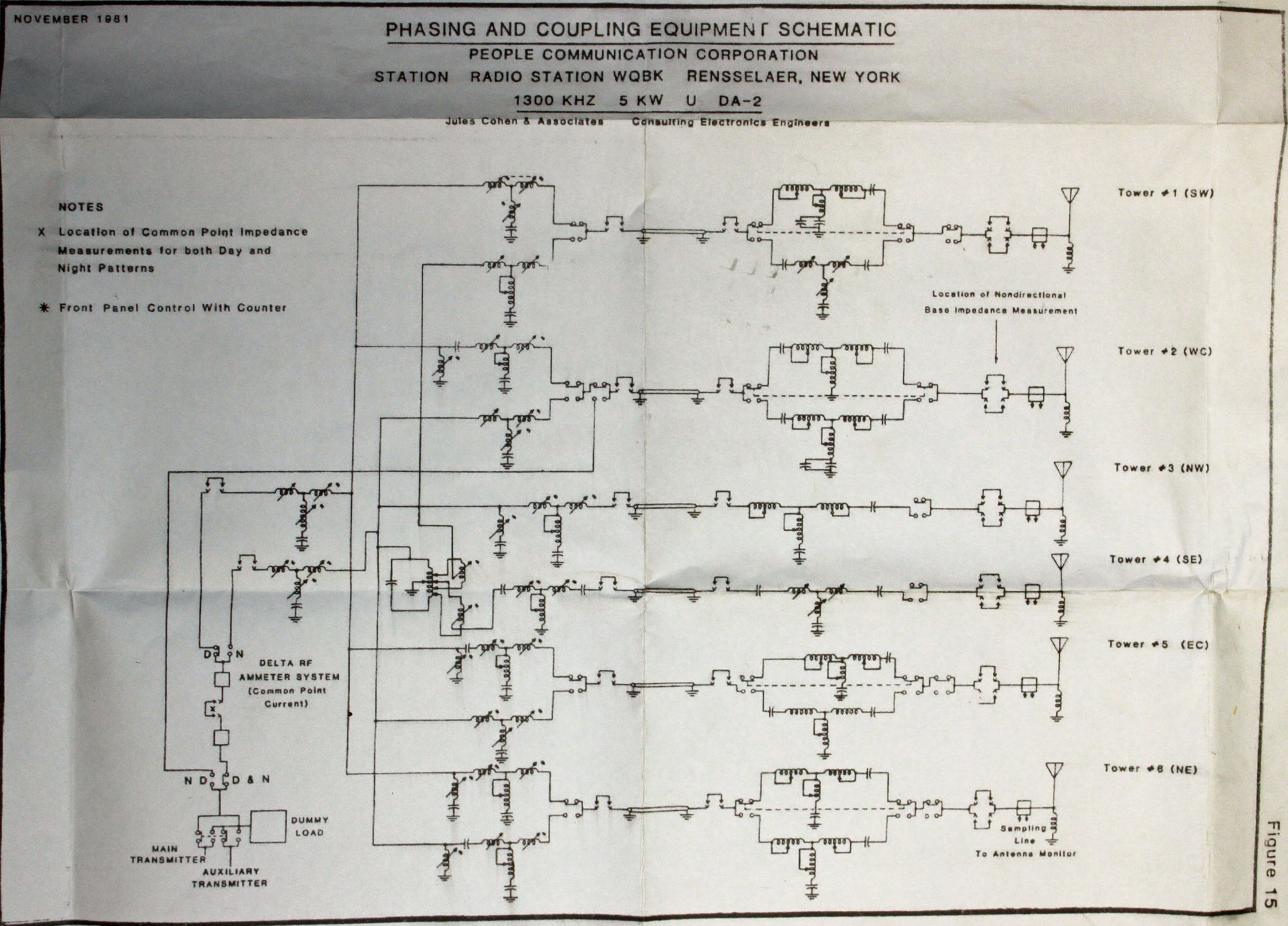
This is the overall schematic of the phasor and ATU:
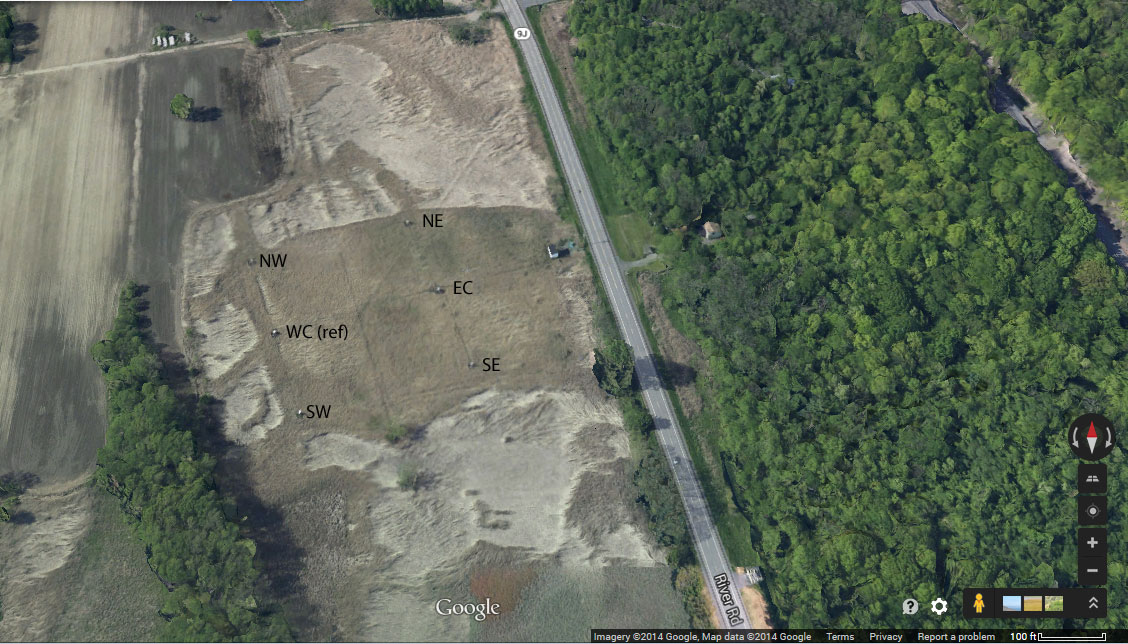
Aerial view of the transmitter site, oriented north:
So, where would you begin? Ask questions in the comments section.

Check the contacts on the inductors for tower 6?
73,
Chuck
Global Warming theory (now called Global Climate change) can explain any anomaly satisfactorily. Therefore an increase in local taxes should bring the array into tolerance. Eventually.
Who is digging up the ground radials?
Chuck, walked out to tower six. The contactor fingers look good, are properly seated. Use the dial up remote control to switch between day and night patterns. Everything checks out okay at tower six. Also checked tower five on my way through, which is also good.
Pete/Pham, the ground system is undistrubed. Ground water levels are normal for this time of year.
Agree with Pete K4OM. Maybe some radians was lost or disconnect
Haven’t figured it out yet, but am puzzled about something else. 13 amps licensed common point current times 50 ohms yields 8450 watts into the antenna system. Station licensed to operate only 5 kW. Am I doing something wrong?
Rod, good question. I should have put in the summary; the station upgraded to 10 kw day, 8.4 kw night about eight years ago.
How about the sampling system? Did someone make phasor adjustments before the sampling was examined?
Shorted turn on tower 3 static drain choke?
Dave, Sample system is good.
Rod, you are closer than anyone else so far, but the problem is not at tower three.
Is there an isocoupler on one of the towers for an STL?
Mike, no isocouplers on any of the towers.
Tower 4…failed tower lighting choke? Had mice take one out recently at one of my sites…
Sounds like a tough one. I would cut down each tower one at a time to see if the problem goes away.
Gregg, towers are unlit, but they do have static drain chokes, so good guess, but not the problem
Bob, I will have to add that procedure to my trouble shooting list…
Okay, I’ll give you a hint:
Tower 2 is the reference tower, moving the phasor power input crank for night time tower 2 in one direction makes the problem better, (common point tracks back toward 50 ohms, phase and power ratios track back toward licensed values) moving the other way makes it worse. The phasor components check out okay…
A Cap in T2’s ATU…maybe a shunt?
I had a case like this as well…..however the “mystery” was pretty mundane. One of the J Plugs had popped out. The transmitter played almost fine into that load, good enough to make me look at samples first….this was the one case when it was not a sample issue.
Here’s where you need to have the self impedance of each feed to each tower and each tower while all the others are floating in a file somewhere.
Don’t really know which tower but maybe a cracked insulator filled with water?
Tower 3 got a lot more power in it than it should. All the others are low. That’s really askew.
Hit the submit then thought of this. Since the day is OK that would mean that the towers are OK since 3 & 4 are “floating” properly and not shorted past the RF switch. If 3 or 4 did have an self impedance change that would more than likely affect the day.
And the winner is… (drum roll sound effect) Robert LaFore!
Tower #2 Night time ATU, one of the shunt capacitors was shorted. There are two .001 mfd capacitors parallel making a .002 mfd shut to ground. I measured both with my trusty fluke meter and found one was shorted, the other good. Replaced the bad one and the array moved much closer to its normal readings.
This type of thing is difficult to diagnose, but by breaking it down into chunks and examining each chunk, you can rule things out. For example, the first thing I did was look at tower six, which seemed the obvious choice. All those components checked out okay. Then tower five, no issues there either. The key was when I turned the common point reactance and resistance cranks with no effect on the common point. Then I deduced something was wrong with the reference tower, which was confirmed by turning the crank.
In the field, fixed mica capacitors can be checked with a fluke or other DVM. This is not the most accurate tool, however, it will tell with the capacitor is shorted or open and give a relatively close measurement which can be compared with the capacitor’s rated value. A DVM cannot tell whether a capacitor is breaking down under voltage, but often those units show other signs.
Darn that reference tower, anyway. 🙂 Luckily, as with Robert, my usual DA problem is a fallen J-plug in the phasor shaken loose by those Multronics contactors that go BAM! twice a day.
I was thinking shunt capacitor in the Tower 2 ATU. That can throw a DA off.
If its not a sample issue, I generally check the shunts first as they seem to be the first to get stressed by mistuning/lightning etc—at least in my experience. AT least you had the day pattern to see that it was normal, leaving either a phasor, or ATU problem, that is a good troubleshooting starting point….it rules out samples, towers, chokes, feed lines etc. (mostly)
The site that I have —- its the 1380 site in Atlanta. Very old, old phasor. There are many splash marks everywhere from molten tar everywhere. Most of the time it plays, but it has a tendency to demand lots of attention all at once.
25kW day from a Nautel NX-50, diplexed with another daytime only station, and then four towers DA with a whopping 4.8kW at night from a DX-10. Nice transmitters wed with ancient feeders—fun stuff.
The site has a “storied” history.
Two self supporters (1948) and two guyed uniform cross section towers.
We recently put this thing on MoM, which was quite fun to model. I think it was the first AM with a mixture of radiators to get a MoM license. MoM was done as a matter of “sanity” in this case!
I have found that an infrared thermometer is helpful in finding bad caps and hot spots. Has anyone else tried it?