This happened recently at an AM station we were doing work for. It seems the modulation monitor was not working when connected to the backup transmitter. A quick check of the RG-58 coax showed that I had the correct cable plugged into the monitor selector relay. Another check with an ohm meter showed the cable was okay. Then I looked at the connector on the monitor port of the transmitter and saw this:
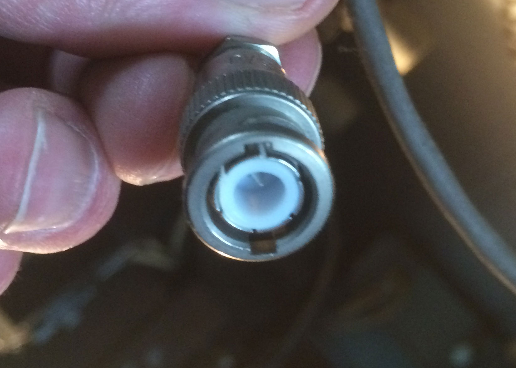
Looks like the pin is too far back in the connector. This is an old-style BNC connector with solder in center pin:
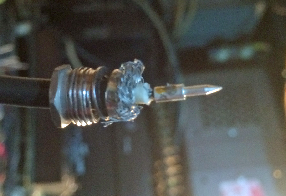
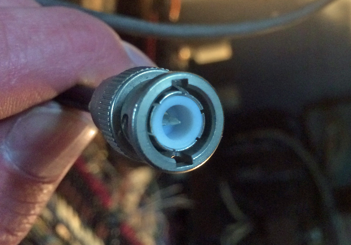
The center pin has a blob of solder on it, preventing it from seating properly in the connector body. I could have lopped it off and applied a new crimp on connector, but my crimp tool was in the car. I didn’t feel like walking all the way through the studio building, out into the parking lot and getting it. Therefore, I used a file and filed off the solder blob then reassembled the connector:
The transmitter was installed in 1986, I think the connector had been like that for a long time.
It may seem like a small detail to have the modulation monitor working on the backup transmitter, however, the modulation monitor is also the air monitor for the studio. Switching to the backup transmitter but not having a working air monitor would likely have caused confusion and the staff might think they are still off the air. I know in this day and age, a lot of station do not even have backup transmitters, but when something is available, it should work correctly.
I like my cool network analyzer and all that, but sometimes it is the Mark 1, Mod 0 eyeball that gets the job done.

Does BNC connectors are the worst.
Maybe it happened when you took the front housing off, but it looks like one or two of those braid strands was fairly close to shorting. There’s a lot about the attachment of this connector that looks ugly, but it seems to have lasted a pretty long time.
I bet Neill and Concelman would shake their heads at this shabby brother to a TNC. A well constructed TNC will work very nicely all the way to 18 gHz.
I was recently called to look at a non-client, off air, Harris HT5 that had chronic low temp related problems. Upon hitting plate ON, HV came on but very low PAI and no drive. After a fair amount of tail chasing, I found that the factory RF cable from the exciter to the IPA had an incorrectly installed connector center pin that would “retract” when subjected to cold temps but work OK with moderate temps.
Substituting a known good cable made it make power reliably in all temps.
Later,
Thanks for the article…I’m glad to see I’m not the only one that’s been stung by that same issue. Soldering BNC’s is not my favorite task.
Now that I’m older I have to put on glasses on top of my glasses to see the small stuff clearly. 🙂
Dave, every year the glasses get bigger and the parts get smaller!
AND at some point that I can’t identify, they stopped putting pin numbers on connectors…
I replaced a Harris SX-1A with a B.E. AM-1A. One morning the B.E. went off the air. They switched to a backup tx and all was well. When I checked the B.E. it was a VSWR fault. The N connector was atop the SX-1A for the antenna. I ordered a male-to-female N extension cable for the AM-1A as the antenna connector was now much lower in a rack.
What I found was that the center pin pulled back and lost contact because I did not do a proper install of the N male connector. It was never an issue because there was no ‘pull’ on the connector to the SX. Now there was. Redoing the install solved the problem permanently.
N connectors are among the worst for center-pin problems and older BNC designs aren’t far behind. A couple of manufacturers make versions with positively-locating center pins, which at least prevent too much or too little protrusion. Still, I count on taking a half-hour to properly assemble a solder center/wrench-clamp outer type N. –I have seen a lot that spin easily on the line when assembled; this is not proper, but a sign it was done wrong. (Seems obvious? Yeah, I thought so, too, but they kept showing up). The solder-center/crimp outer versions are a lot faster to assemble and most have some means of positively locating the center pin — Times Microwave’s connectors for their LMR series line are good and don’t require an exotic crimper. There are similar connectors for the standard RG-series coaxial cables. (Paladin and some of the copycat companies have a nice crimp tool with a wide assortment of relatively inexpensive dies, if you find yourself doing more than a few connections.)
BNC jack welding is simple, but wanted to weld the correct technique to a precision guidance from someone with experience, if so please suggest a proper welding ….
There make BNC connectors that use a center pin that locks into place with a small ridge, it fits into the insulator with a “snap”.
They are not truly captive pin style of connectors like some type N connectors are, but should prove to be substantially better when it comes to the center in staying in place.
Look up Connex (an X in the Amphenol connector line indicates made in China!) 112120
I do not like solder connectors these days (ah, did previous comment mean solder rather than weld?) when there are great crimp connectors available.
Reid Brandon W6MTF