A quick glance at almost any circuit board these days will show that almost all of the components are surface-mounted. They are small rectangles or squares that sit on top of the circuit board. This is different from the through-hole components that were used for many years and are still found in older equipment. There are radio engineers who feel that surface mount components are too hard to work on, thus the boards are not repairable.
As with anything in the engineering field, there needs to be a cost/benefit analysis. Most computer component boards, things like NICs, modems, sound cards, VGA cards are very inexpensive, and often times it would be more expensive to repair the board than it would to buy a new one. In other situations, however, local repair of circuit boards makes good sense and can be a good learning tool.
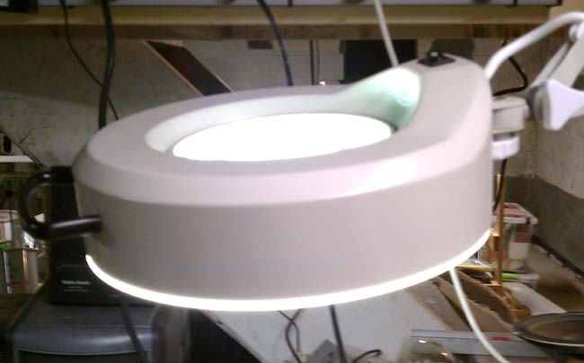
Consoles and transmitters offer some good opportunities for local repair, provided the schematics are available. SMT component troubleshooting is the same as through-hole troubleshoots, except the components are smaller. That is where a magnifying glass comes in handy. I purchased a magnifying glass/light to work on SMT boards.
Soldering and unsoldering techniques are also different. A temperature controlled soldering iron with a small tip is important. I find the easiest way to unsolder a component is with solder wick. Once most of the solder has been wicked up, a brief touch of the iron and the component will come off. Small resistors and capacitors are fairly rugged, but should not be overheated. Semiconductor components such as diodes, transistors and ICs are susceptible to heat damage and Electro Static Discharge (EDS). A grounding wrist strap should always be used when handling semiconductor components. Soldering iron temperature should be enough to quickly melt the solder and heat the connection surface without overheating the SMT component. Lead free solder requires slightly higher temperatures than the traditional 60/40 rosin core.
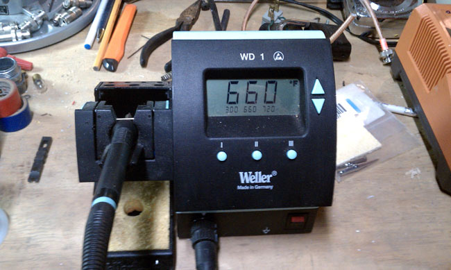
A temperature-controlled soldering station is a must. Too much heat will damage components and boards, too little will make soldering SMT an arduous task.
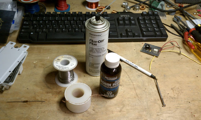
Other soldering supplies include liquid flux, desoldering wick, flux remover and 55/40/5 solder. The desoldering wick makes it easy to clean up an errant solder deposits and is the best way to desolder surface mount components. I have had limited success using a solder pump on surface mount boards. They do come in handy for RF MOSFETS, which have large tabs, often with liberal amounts of solder applied at the factory.
Soldering new components:
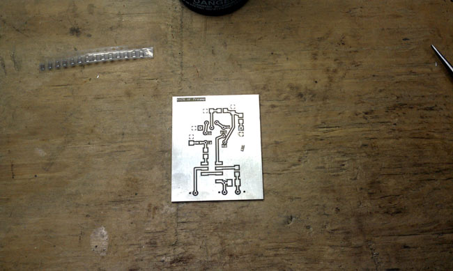
A typical 0.1 uf capacitor is placed on the surface mount board and ready to be soldered. These components are all small, but I would characterize this as a medium sized one. There are some very small diodes, ICs and other devices that require the magnifying glass to identify pins and polarity.
The best way that I have found to solder components onto a surface mount board is to use a little bit of liquid flux on the board.
Using tweezers or small needle nose pliers, place the component.
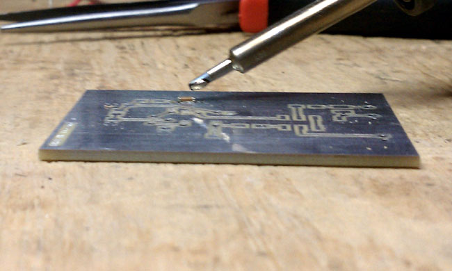
Wet the end of the soldering iron with a little bit of solder.
Using the placing tool, hold the component in place and touch one of the pads with the soldering iron. This should tack the component in place. Solder the component to the other pad using the soldering iron and solder. Then come back and touch up the tacked side. I have found that 600 degrees F is a good temperature to quickly melt the solder, while not heating up the component too much.
Sorry I could not get pictures of the actually process, I don’t have enough hands to hold the soldering iron, hold the component down and take a picture.
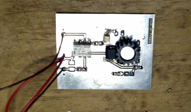
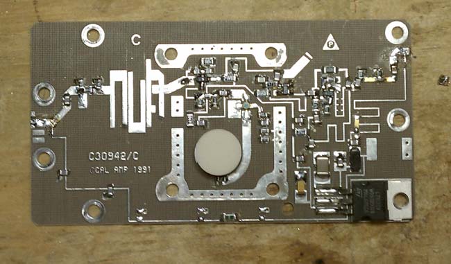
The completed preamplifier. I have been calling this an HF preamp, because that is its intended use. In practice, this preamp should work well from 50 KHz up to about 75 MHz, with 3dB points at 30 KHz and 100 MHz.
The Norton design is an inverse feed back and using the 1N5109 transistor, which has input and output impedance of 50 ohms, makes it simple to implement. In testing, I found this unit has about 10-11 dB of gain with about 4 dB of noise. The use of SMT makes the design stable and I didn’t see any evidence of oscillations when testing it. More on the preamp here. I installed it out at the base of my K9AY antenna and it can be remotely turned on and off as needed. My main reason for wanting it is to overcome the 6.5 dB signal loss in the four port hybrid receiver coupler and transmission line I use. Truth be told, most of the time it is off.

Extreme care and being in the mood to repair SMT are the problems with this technology; therefore basically another throw-away to clog the landfills with leached metals permeating groundwater. And when the commercial manufacturers stop making the microstrips you are SOL. Motorola RF striplines used a ceramic material with the plating on the other side as a ground plane. Very tiny, almost indistinguishable cracks could occur from temperature cycling causing failure. And, what about repair at the transmitter site? Almost impossible! Spare PA assemblies are needed so that the defective PA can be returned to the shop where decent lighting, special soldering tools and silver alloy solder is used. Personally, I would rather replace a tube.
I wouldn’t try to make repairs at the transmitter site, that’s why it is good policy to stock extra RF amps, power supplies, fans and what not for solid state transmitters. I have successfully repairs several Harris RF amps for the Z series transmitters using these methods. It does take a little extra time, but in the end, locally repairing spares gets them back onto the shelf at the transmitter site faster and can save money.