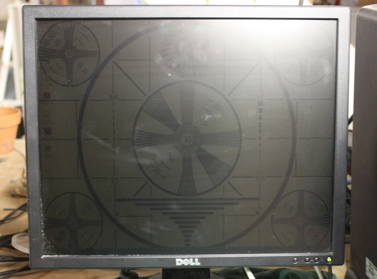
I have seen many a Dell LCD computer monitor go south for want of a $0.50 part. Dell must have gotten a hold of a bad batch of capacitors because almost invariably, the problem is with the power supply capacitors for the backlight. The symptoms are; the monitor goes very dim and can only be read when shining a light on it, or the power button flashes green.
A new Dell 19-inch (E1914H) monitor runs about $90.00 – 110.00. I can repair a defective unit in about 20-30 minutes or so, which makes it worthwhile for the client. When repairing equipment, the cost of labor and parts balanced across the cost of new equipment should be a prime consideration. Sometimes, it is simply not worth the time to repair something. In others, like this instance, it makes sense as long as the repair is simple.
This is a Dell E198FPf LCD monitor. After the initial diagnosis:
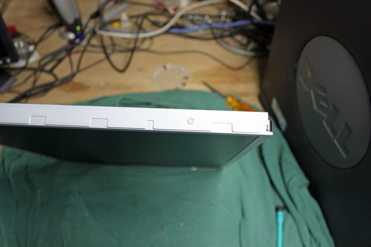
The first step is to remove the stand and the four screws behind the stand bracket.

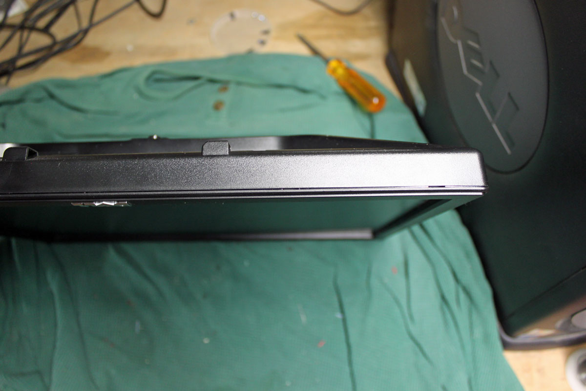
The hardest thing about this repair is getting the bezel off. Dell uses a bezel around the monitor face that uses little plastic clips to hold it in place. To get the bezel off, one needs to press the clips toward the center of the monitor while lifting it up. It requires the careful application of force.
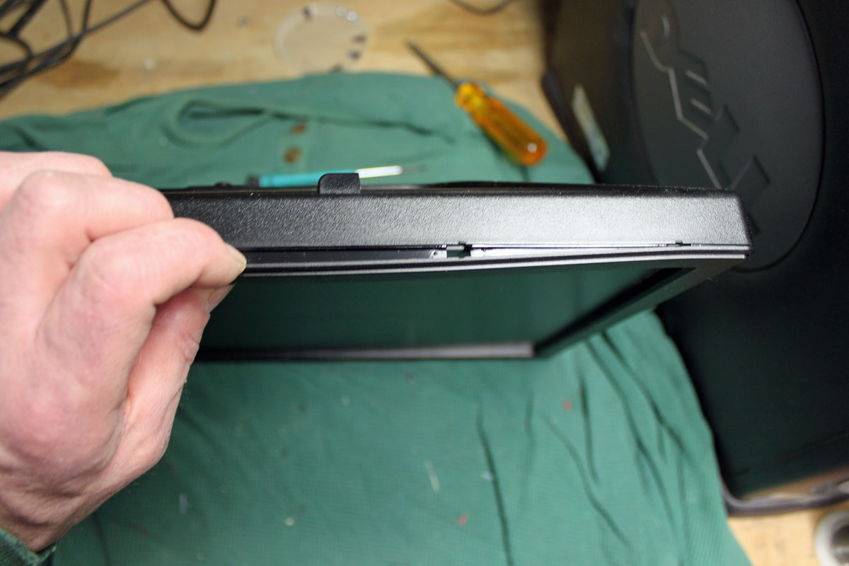
I start on the bottom and use a small screwdriver in one of the slots to get it started. I start on the bottom because if the plastic gets a little marred, no one will see it when the repair is finished. Once the first clip is released, then the others and be released by twisting the bezel carefully toward the center of the monitor while lifting.
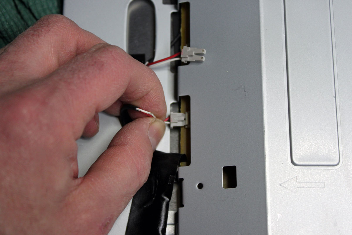
Once the bezel is removed, the wiring needs to be disconnected. This consists of the backlight, the data buss, and sometimes the on/off switches, which are mounted on the bezel.
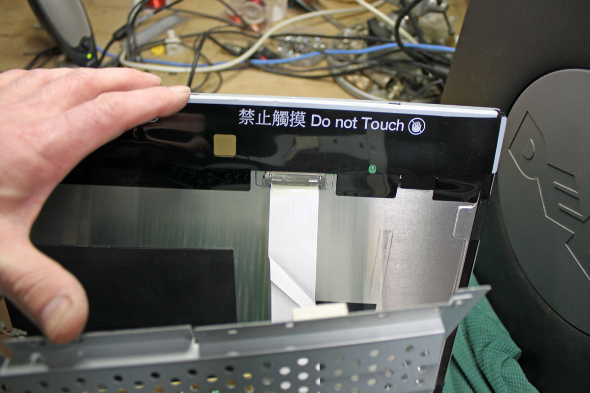
After all the wiring is removed, there are either two or four screws that hold the power supply to the monitor screen.
Finally, the power supply board is exposed. Depending on the model of the monitor, the hex head screws that hold the VGA connector may need to be taken off. Sometimes not.
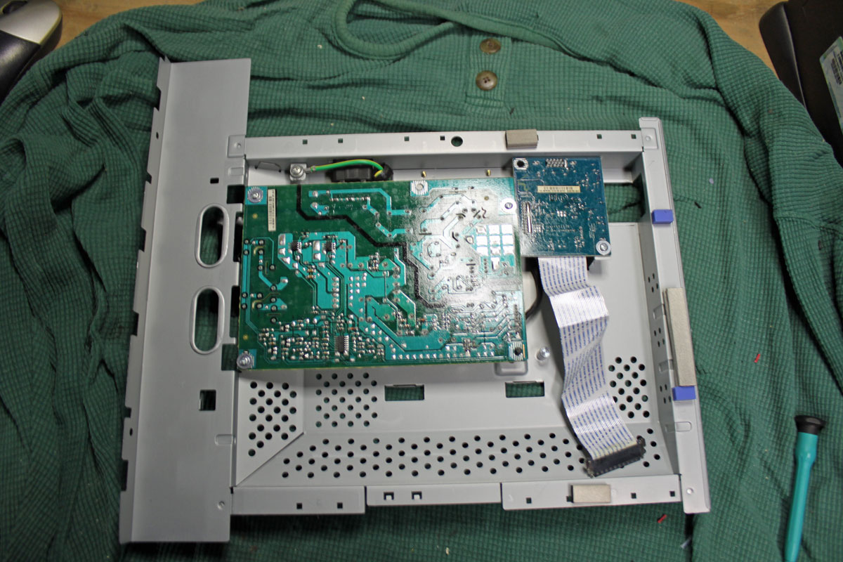
Removing the screws on the back of the power supply board exposes the capacitors and other components.

And the culprit is discovered. These two bulging capacitors are causing the LCD monitor backlight power supply shut down making the monitor unusable. The larger one is a 1000 uF 25 volt and the smaller is 680 uF 25 volt. I replaced both with in kind 35 volt units. I also took the liberty of replacing the rest of the electrolytics on the power supply board (total of five additional capacitors). While the unit is disassembled, it is far easier to replace all the $0.50 components than to do it one at a time over the next few years as each fails. This monitor should be good for another 5 years of service at least. These values vary somewhat from monitor to monitor. Also, if only repairing one or two monitors, the parts can be obtained at Radio Shack for $1.99 each.
It is a good way to regenerate equipment, even if they are set aside as spares.